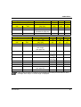
1
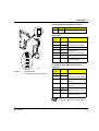
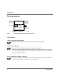
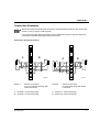
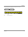
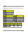
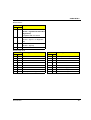
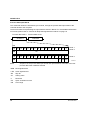
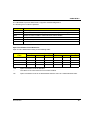
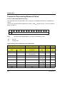
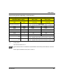
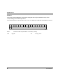
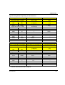
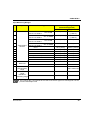
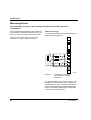
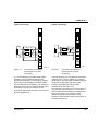
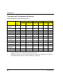
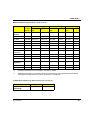
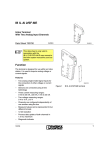
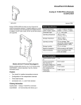
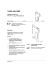
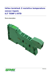
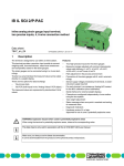
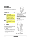
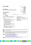
VARIO RTD 2
I/O Extension Module
With Two Analog Input Channels for the
Connection of Temperature Shunts (RTD)
User Manual
02/2003
5 7 5 5 1 0 0 1
This data sheet is only valid in
association with the documents of the
used fieldbus coupler
Function
The VARIO RTD 2 terminal is designed for use
within an VARIO station. This terminal provides
a two-channel input module for resistive
temperature sensors. This terminal supports
platinum or nickel sensors according to the DIN
standard and SAMA Directive. In addition, CU10,
CU50, CU53, KTY81 and KTY84 sensors are
supported.
The measuring temperature is represented by a
16-bit value in two data words (one word per
channel).
5 7 5 5 0 0 1 0
Figure 1
Terminal VARIO RTD 2
with connector fitted
Features
–
Two inputs for resistive temperature sensors
–
Configuration of the channels via fieldbuss
–
Measured values can be represented in 3
different formats.
–
Connection of sensors in 2-, 3- and 4-wire
technology
9499-040-68911
All modules will be delivered including
connectors and labeling fields
1
VARIO RTD 2
Table of Contents
Function ........................................................................................................................................... 1
Safety Note ...................................................................................................................................... 4
Installation Instructions .....................................................................................................................4
Internal Circuit Diagram ................................................................................................................... 5
Electrical Isolation ............................................................................................................................6
Connection ....................................................................................................................................... 6
Connection Examples ...................................................................................................................... 7
Programming Data ........................................................................................................................... 8
Process Data Words ........................................................................................................................ 8
Formats for Representing Measured Values ................................................................................. 16
Measuring Ranges ......................................................................................................................... 22
Measuring Errors ............................................................................................................................ 24
Tolerance and Temperature Response ......................................................................................... 28
Technical Data ............................................................................................................................... 30
Ordering Data ................................................................................................................................. 32
2
9499-040-68911
VARIO RTD 2
Local Diagnostic and Status Indicators
D
Des.
D
R T D
1
2
1 .1
1
1
2 .1
1 .2
2
2
2 .2
1 .3
3
3
2 .3
1 .4
4
4
2 .4
Meaning
Green Bus diagnostics
Pin Assignment for 2- and 3-Wire
Termination
Terminal
Points
Signal
Assignment
1.1
I1+
RTD sensor 1
1.2
I1-
Constant current supply
1.3
U1-
Measuring input sensor 1
2.1
I2+
RTD sensor 2
2.2
I2-
Constant current supply
2.3
U2-
Measuring input sensor 2
1.4, 2.4
Shield
Shield connection
(channel 1 and 2)
Pin Assignment for 4-Wire Termination
on Channel 1 and 2-Wire Termination on
Channel 2
5 7 5 5 0 0 0 2
Figure 2
Color
VARIO RTD 2
with the appropriate connector
Terminal
Points
Signal
Assignment
1.1
I1+
RTD sensor 1
1.2
I1-
Constant current supply
1.3
U1 -
Measuring input
sensor 1
2.3
U1 +
Measuring input
sensor 1
2.1
I2+
RTD sensor 2
2.2
I2-
Constant current supply
1.4, 2.4
Shield
Shield connection
(channel 1 and 2)
A sensor can only be connected to
channel 1 using 4-wire technology.
9499-040-68911
3
VARIO RTD 2
Safety Note
During configuration, ensure that no isolating voltage is specified between the analog
inputs and internal bus. This means that the user must provide signals with safe isolation
for the thermistor detection, if required.
Installation Instructions
High current flowing through the potential jumpers UM and US raises the temperature of the potential
jumpers and the temperature inside the terminal. Observe the following instructions to keep the
current flowing through the voltage jumpers of the analog terminals as low as possible:
Each of the analog terminals needs a separate main circuit!
If this is not possible in your application and if you are using analog terminals in a main
circuit together with other terminals, place the analog terminals behind all the other
terminals at the end of the main circuit.
4
9499-040-68911
VARIO RTD 2
Internal Circuit Diagram
Key:
IN T E R B U S
O P C
OPC
U
U
U
L +
A N A
L -
INTERBUS protocol chip
Optocoupler
x x x
2 4 V
X X X
µ P
±5 V
M U X
µ P
R E F
R E F
M U X
E E P R O M
E E P R O M
DC/DC converter with electrical
isolation
Microprocessor with multiplexer
and analog/digital converter
Reference voltage
Electrically erasable
programmable read-only memory
Amplifier
+ 2 4 V (U S )
1
+ 2 4 V (U M )
5 7 5 5 1 0 0 3
Figure 3
9499-040-68911
Internal wiring of the terminal
points
5
VARIO RTD 2
Electrical Isolation
IN T E R B U S L o c a l b u s (IN )
U L (7 .5 V D C )
B u s in te r fa c e
O P C
IN T E R B U S L o c a l b u s (O U T )
U L (7 .5 V D C )
U
U
A N A
(2 4 V D C )
± 5 V
± 5 V
G r o u n d p o te n tia l
Bild 4
A N A
2 4 V
I/O
in te r fa c e
a n d
m ic r o p r o c e s s o r
(2 4 V D C )
A
B
E le c tr ic a l is o la tio n
b e tw e e n a re a
A a n d B
A n a lo g in p u ts
5 7 2 2 A 0 0 7
Electrical isolation of the single function areas
Connection
Connection of the Thermocouples
Always connect temperature shunts using shielded, twisted-pair cables.
Connection of the Shield
The connection of the shield is shown in the examples (Figure 5).
Connect the shielding of the Inline terminal using the shield connector clamp. The clamp
connects the shield directly to FE on the terminal side. Additional wiring is not necessary.
Isolate the shield at the sensor.
Sensor Connection In 4-Wire Technology
A sensor can only be connected to channel 1 in 4-wire technology. In this case, the sensor
on channel 2 can only be connected in 2-wire technology!
6
9499-040-68911
VARIO RTD 2
Connection Examples
When connecting the shield at the terminal you must insulate the shield on the sensor side
(shown in gray in Figure 5 and Figure 6).
Use a connector with shield connection when installing the sensors. Figure 5 shows the
connection schematically (without shield connector).
Connection of Passive Sensors
D
D
2 R T D
A
1
2 R T D
B
2
A
1
B
2
I1+
1
1
I2+
I1+
1
1
I2+
I12
2
I2-
I12
2
I2-
3
3
4
4
U
2
U
U
1
3
3
1
+
4
4
5 7 5 5 B 0 1 1
5 7 5 5 B 0 0 4
Figure 5
Sensor connections
in 2- and 3-wire technology with
shield connection
Figure 6
Sensor connections
in 4-wire technology with shield
connection
A
Channel 1; 2-wire technology
A
Channel 1; 4-wire technology
B
Channel 2; 3-wire technology
B
Channel 2; 2-wire technology
9499-040-68911
7
VARIO RTD 2
Programming Data
ID code
7Fhex (127dec)
Length code
02hex
Input address area
4 bytes
Output address area
4 bytes
Parameter channel (PCP)
0 bytes
Register length (bus)
4 bytes
Process Data Words
Output Data Words for the Configuration of the Terminal (see page 11)
(Word.bit)
view
Word 0
Word
Bit
15
14
13
12
Byte
Channel 1
Assignment Configu- Connection
ration
type
(Word.bit)
view
Word
Bit
7
6
5
4
15
14
13
12
7
6
5
4
3
2
1
0
2
1
0
Byte 1
3
2
1
0
7
6
5
4
Resol- Format
ution
R0
11 10
9
8
7
6
5
Byte 2
Byte
Channel 2
Assignment Configu- Connection
ration
type
8
8
3
Sensor type
Word 1
(Byte.bit)
view
Bit
9
Byte 0
(Byte.bit)
view
Bit
11 10
7
6
5
4
4
3
2
1
0
2
1
0
Byte 3
3
2
1
R0
0
7
6
5
4
Resol- Format
ution
3
Sensor type
9499-040-68911
VARIO RTD 2
Assignment of the Terminal Points to the Input Data Word (see page 14)
(Word.bit)
view
Word
(Byte.bit)
view
Byte
Terminal
points
channel 1
Signal
(Word.bit)
view
Bit
Bit
15 14 13 12 11 10
9
8
Shield (FE)
Byte
Terminal
points
channel 2
Signal
Bit
7
6
5
4
3
2
1
0
5
4
3
2
1
0
7
6
5
4
3
2
1
0
Terminal point 1.1: I1+ sensor 1
Terminal point 1.3 U1- sensor 1
Terminal point 1.4
Word 1
15 14 13 12 11 10
9
8
7
6
5
Byte 2
7
6
5
4
3
4
3
2
1
0
2
1
0
Byte 3
2
1
0
7
6
5
4
3
Terminal point 2.1: I2+ sensor 2
Signal reference Terminal point 2.2: I2- sensor 2
Shielding
6
Byte 1
Word
Bit
7
Byte 0
Signal reference Terminal point 1.2: I1- sensor 1
(Byte.bit)
view
9499-040-68911
Word 0
Terminal point 2.3 U1+ sensor 2
Terminal point 2.4
9
VARIO RTD 2
Process Data Output Words
You can configure the channels of the terminal
with the two process data output words. The
following configurations are possible for every
channel independent of the other channel:
–
Sensor connection method
–
Value of the R0 reference resistance
–
Setting the resolution
–
Selection of the format for representing the
measured values
–
Setting the sensor type
The two channels are dependent on each other
for the connection method. If the 4-wire mode is
activated for channel 1, channel 2 can only be
operated using the 2-wire connection method.
The 4-wire connection method is only available
for channel 1.
If you change the configuration, the
corresponding channel is re-initialized. The
message "Measured value invalid" (error code
E8004hex) appears in the process data output
words for 100 ms (maximum).
If the configuration is invalid, the message
"Configuration invalid" appears (error code
8010hex).
Please note that extended
diagnostics is only possible if
IB standard is configured as the
format for representing the measured
values. Since this format is preset on
the terminal, it can be used straight
away after power up.
Configuration errors are indicated by the
corresponding error code, as long as the
IB standard format is configured as the format
for representing the measured values.
The configuration setting is saved in a volatile
memory. It must be transmitted in each
INTERBUS cycle.
After the Inline station has been powered up, the
message "Measured value invalid" (error code
8004hex) appears in the process input words.
After 1 s (maximum) the preset configuration is
accepted and the first measured value is
available.
Default:
Connection:
10
3-wire technology
R0 :
100 W
Resolution:
0.1°C
Format:
Format 1 (IB standard)
Sensor type:
PT 100 (DIN)
9499-040-68911
VARIO RTD 2
One process data output word is available for the configuration of each channel.
P ro c e s s d a ta w o rd 1
P ro c e s s d a ta w o rd 0
C h a n n e l 1
C h a n n e l 2
M S B
1 5
L S B
1 4
1 3
1 2
C o n fig u r a tio n C o n n e c tio n
ty p e
Bild 7
9499-040-68911
1 1
1 0
9
R 0
8
7
6
R e s o lu tio n
5
4
F o rm a t
3
2
1
0
S e n s o r ty p e
5 7 5 5 A 0 0 6
Process data output words
11
VARIO RTD 2
Bit 15 and bit 14:
You must set bit 15 of the corresponding output word to 1 to configure the terminal or a certain
channel. If bit 15 = 0 the preset configuration is active. Bit 14 is of no importance at present, therefore
it should be set to 0.
Bit 13 and bit 12:
Code
Connection Type
Dec. Bin.
0
00
3-wire
1
01
2-wire
2
10
4-wire (only channel 1)
3
11
Reserved
Bit 11 through bit 8
Code
R0 [W]
Code
Dec. Bin.
R0 [W]
Dec. Bin.
0
0000 100
8
1000 240
1
0001 10
9
1001 300
2
0010 20
10
1010 400
3
0011 30
11
1011 500
4
0100 50
12
1100 1000
5
0101 120
13
1101 1500
6
0110 150
14
1110 2000
7
0111 200
15
1111 3000 (adjustable)
Bit 7 and bit 6:
Code
Resolution for Sensor Type
Dec. Bin. 0 through 10
12
13
14
15
0
00
0.1°C
1%
0.1 W
1W
1
01
0.01°C
0.1%
0.01 W
0.1 W
2
10
0.1°F
Reserved
Reserved
Reserved
3
11
0.01°F
9499-040-68911
VARIO RTD 2
Bit 5 and bit 4:
Code
Format
Dec. Bin.
0
00
Format 1: IB standard
(15 bits + sign bit with extended
diagnostics)
Compatible with ST format
1
01
Format 2
(12 bits + sign bit + 3 diagnostic
bits)
2
10
Format 3
(15 bits + sign bit)
3
11
Reserved
Bit 3 through bit 0:
Code
Sensor Type
Dec. Bin.
Code
Sensor Type
Dec. Bin.
0
0000 Pt DIN
8
1000 Ni 500 (Viessmann)
1
0001 Pt SAMA
9
1001 KTY 81-110
2
0010 Ni DIN
10
1010 KTY 84
3
0011 Ni SAMA
11
1011 Reserved
4
0100 Cu10
12
1100 Reserved
5
0101 Cu50
13
1101 Potentiometer [%]
6
0110 Cu53
14
1110 Linear R: 0 through 400 W
7
0111 Ni 1000 (Landis & Gyr)
15
1111 Linear R: 0 through 4000 W
9499-040-68911
13
VARIO RTD 2
Process Data Input Words
The measured values are transmitted, per channel, through the process data input words to the
controller board or the computer.
The three formats for representing the input data are shown in Bild 8. For more detailed information
on formats, please refer to "Formats for Representing Measured Values" on page 16.
P ro c e s s d a ta w o rd 1
P ro c e s s d a ta w o rd 0
C h a n n e l 1
C h a n n e l 2
M S B
1 5
L S B
1 4
1 3
1 2
1 1
1 0
9
7
6
5
4
3
2
1
0
8
7
6
5
4
3
2
1
0
O C
O R
A V
S B
1 5
F o rm a t 1
F o rm a t 3
8
1 4
1 3
1 2
1 1
1 0
9
A V
S B
0
F o rm a t 2
5 7 5 5 A 0 0 9
Bild 8
Sequence of the process data input words and representation of the bits of the first
process data word in different formats
MSB Most significant bit
LSB
Least significant bit
SB
Sign bit
AV
Analog value
0
Reserved
OC
Open circuit/short-circuit
OR
Over range
14
9499-040-68911
VARIO RTD 2
The "IB standard" process data format 1 supports extended diagnostics.
The following error codes are possible:
Code (hex)
Error
8001
Over range
8002
Open circuit or short-circuit (only available in the temperature range)
8004
Measured value invalid/no valid measured value available
8010
Configuration invalid
8040
Terminal faulty
8080
Under range
Open Circuit/Short-Circuit Detection:
Open circuit is detected according to the following table:
Faulty Sensor
Cable
Temperature Measuring Range
Resistance Measuring Range
2-wire
3-wire
4-wire
2-wire
3-wire
4-wire
I+
Yes
Yes
Yes
Yes
Yes
No
I-
Yes
Yes
Yes
Yes
Yes
No
U+
–
–
Yes
–
–
Yes
U-
–
Yes
Yes
–
Yes
Yes
Yes
Open circuit/short-circuit is detected.
–
The cable is not connected in this connection method.
No
Open circuit/short-circuit is not detected because the value is a valid measured value.
9499-040-68911
15
VARIO RTD 2
Formats for Representing Measured Values
Format 1: IB Standard (Default Setting)
The measured value is represented in bits 14 through 0. An additional bit (bit 15) is available as a
sign bit.
This format supports extended diagnostics. Values > 8000hex indicate an error. The error codes are
listed on page 15.
1 5
1 4
1 3
1 2
1 1
1 0
9
8
7
6
5
4
3
2
1
0
A V
S B
5 5 6 4 1 0 0 8
Bild 9
Measured value representation in format 1 (IB standard; 15 bits)
SB
Sign bit
AV
Analog value
Typical Analog Values Depending on the Resolution
Sensor Type (Bits 3 through 0)
Resolution (Bits 7 and 6)
Process Data (= Analog Value)
hex
dec
8002
–
8001
–
16
0 through 10
00bin / 10bin
0.1°C / 0.1°F
[°C] / [°F]
13
00bin
1%
[%]
14
00bin
0.1 W
[W]
15
00bin
1W
[W]
–
–
–
400
–
4000
–
4000
(40 x R0)
10
(0.10 x R0)
1
(0.01 x R0)
0
–
–
400
–
4000
1.0
10
0.1
1
0
–
0
–
2710
0FA0
10000
4000
Open circuit
Over range
(see page 23)
1000.0
400.0
00A0
10
1.0
0001
1
0.1
0000
FFFF
0
-1
0
-0.1
9499-040-68911
VARIO RTD 2
Sensor Type (Bits 3 through 0)
Resolution (Bits 7 and 6)
Process Data (= Analog Value)
hex
dec
FC18
-1000
8080
8002
Sensor Type (Bits 3 through 0)
Resolution (Bits 7 and 6)
Process Data (= Analog Value)
hex
dec
8002
–
8001
–
0 through 10
00bin / 10bin
0.1°C / 0.1°F
[°C] / [°F]
13
00bin
1%
[%]
14
00bin
0.1 W
[W]
15
00bin
1W
[W]
-100.0
Under range
(see table on page 23)
Short circuit
–
–
–
–
–
–
–
–
–
0 through 10
01bin / 11bin
0.01°C / 0.01°F
[°C] / [°F]
13
01bin
0.1%
[%]
14
01bin
0.01 W
[W]
15
01bin
0.1 W
[W]
–
–
–
325.12
–
3251.2
1000.0
(10 x R0)
100.0
(1 x R0)
0.1
(0.01 x R0)
0
–
–
–
100.00
1000.0
10.00
100.0
0.01
0.1
0
–
–
–
0
–
–
–
–
–
–
2710
10000
Open circuit
> 325.12
Over range
(see page 23)
100.00
03E8
4000
10.00
0001
1
0.01
0000
FFFF
D8F0
8080
0
-1
-10000
0
-0.01
-100.00
Under range
(see page 23)
Short-circuit
8002
If the measured value is outside the representation area of the process data, the error
message "Over range" or "Under range" is displayed.
9499-040-68911
17
VARIO RTD 2
Format 2
This format can be selected for each channel using bits 5 and 4 (bit combination 01bin) of the
corresponding process data output word.
The measured value is represented in bits 14 through 3. The remaining 4 bits are available as sign
and error bits.
1 5
1 4
1 3
1 2
1 1
1 0
9
8
7
6
5
4
A V
S B
3
0
2
1
0
O C
O R
5 5 2 0 0 0 6 0
Bild 10
Measured value representation in format 2 (12 bits)
SB
Sign bit
AV
Analog value
0
Reserved
OC
Open circuit/short-circuit
OR
Over range
18
9499-040-68911
VARIO RTD 2
Typical Analog Values Depending on the Resolution
Sensor Type (Bits 3 through 0)
RTD Sensor (0 through 13)
Resolution (Bits 7 and 6)
00bin / 10bin
01bin / 11bin
Process Data (= Analog Value)
0.1°C / 0.1°F
[°C] / [°F]
0.01°C / 0.01°F
[°C] / [°F]
hex
dec
xxxx xxxx xxxx xxx1bin
Over range
(AV = positive final value from the table on page 23)
2710
10000
1000.0
100.00
03E8
1000
100.0
10.00
0008
8
0.8
0.08
0000
0
0
0
FFF8
-8
-0.8
-0.08
FC18
-1000
-100.0
-10.00
xxxx xxxx xxxx xxx1bin
Under range
(AV = negative final value from the table on page 23)
xxxx xxxx xxxx xx1xbin
Open circuit/short-circuit
(AV = negative final value from the table on page 23)
AV
Analog value
x
Can have the values 0 or 1
If the measured value is outside the representation area of the process data, bit 0 is set to
1.
On an open circuit/short-circuit, bit 1 is set to 1.
9499-040-68911
19
VARIO RTD 2
Format 3
This format can be selected for each channel using bits 5 and 4 (bit combination 10bin) of the
corresponding process data output word.
The measured value is represented in bits 14 to 0. An additional bit (bit 15) is available as a sign bit.
1 5
1 4
1 3
1 2
1 1
1 0
9
8
7
6
5
4
3
2
1
0
A V
S B
5 5 6 4 1 0 0 8
Bild 11
SB
20
Measured value representation in format 3 (15 bits)
Sign bit
AV
Analog value
9499-040-68911
VARIO RTD 2
Typical Analog Values Depending on the Resolution
Sensor Type (Bits 3 through 0)
RTD Sensor (0 through 10)
Linear Resistance (15)
Resolution (Bits 7 and 6)
00bin / 10bin
00bin
Process Data (= Analog Value)
0.1°C / 0.1°F
[°C] / [°F]
1W
[W]
hex
dec
7FFF
32767
–
Upper limit value* +1 LSB
Over range
–
7D00
32000
–
2000
2710
10000
1000.0
625
000A
10
1
0.625
0001
1
0.1
0.0625
0000
0
0
0
FFFF
-1
-0.1
–
FC18
-1000
-100.0
–
Lower limit value* - 1 LSB
Under range
–
Lower limit value* - 2 LSB
Open circuit/short-circuit
–
Sensor Type (Bits 3 through 0)
RTD Sensor (0 through 10)
Linear Resistance (15)
Resolution (Bits 7 and 6)
01bin / 11bin
01bin
Process Data (= Analog Value)
0.01°C / 0.01°F
[°C] / [°F]
0.1 W
[W]
hex
dec
7FFF
32767
–
Upper limit value* + 1 LSB
*
> 2048
Over range
> 4096
–
7D00
32000
320.00
4000
2710
10000
100.0
1250
0001
1
0.1
0.125
0000
0
0
0
FFFF
-1
-1.0
–
D8F0
-10000
-100.0
–
Lower limit value* - 1 LSB
Under range
–
Lower limit value* - 2 LSB
Open circuit/short-circuit
–
The limit values can be found on page 23.
9499-040-68911
21
VARIO RTD 2
Measuring Ranges
Measuring Ranges Depending on the Resolution (IB Standard Format)
Resolution
Temperature Sensors
00
-273°C to +3276.8°C
Resolution: 0.1°C
01
-273°C to +327.68°C
Resolution: 0.01°C
10
-459°F to +3276.8°F
Resolution: 0.1°F
11
-459°F to +327.68°F
Resolution: 0.01°F
Temperature values can be
converted from °C to °F with this
formula:
T [° F ] = T [° C ] x
9
5
Where:
T [°F]
Temperature in °F
T [°C]
Temperature in °C
22
+ 3 2
9499-040-68911
VARIO RTD 2
Input Measuring Ranges
No
.
Input
Sensor Type
Measuring Range:
(Software Supported)
Lower Limit
Upper Limit
-200°C (-328°F)
+850°C
(+1562°F)
-200°C (-328°F)
+850°C
(+1562°F)
-60°C (-76°F)
+180°C (+356°F)
-60°C (-76°F)
+180°C (+356°F)
Cu10
-70°C (-94°F)
+500°C (+932°F)
5
Cu50
-50°C (-58°F)
+200°C (+392°F)
6
Cu53
-50°C (-58°F)
+180°C (+356°F)
7
Ni 1000 L&G
-50°C (-58°F)
+160°C (+320°F)
8
Ni 500 (Viessmann)
-60°C (-76°F)
+250°C (+482°F)
9
KTY81-110
-55°C (-67°F)
+150°C (+302°F)
10
KTY84
-40°C (-40°F)
+300°C (+572°F)
0%
4 kW / R0 x 100%
(400% maximum)
0W
400 W
0W
4000 W
0
Pt
R0 10 W to 3000 W
Acc. to DIN
1
Pt
R0 10 W to 3000 W
Acc. to SAMA
2
Ni
R0 10 W to 3000 W
Acc. to DIN
Ni
R0 10 W to 3000 W
Acc. to SAMA
3
4
11
12
13
Temperature
sensors
Reserved
Relative
potentiometer
range
14
Linear
resistance
15 measuring range
The number (No.) corresponds to the code of the sensor type in bit 3 through bit 0 of the
process data output word.
9499-040-68911
23
VARIO RTD 2
Measuring Errors
Systematic Measuring Errors During Temperature Measurement With Resistance
Thermometers
When measuring temperatures with resistance
thermometers, systematic measuring errors are
often the cause of incorrect measured results.
4-Wire Technology
The 4-wire technology is the most precise way of
measuring (see Figure 12).
There are three main ways to connect the
sensors: 2-, 3- and 4- wire technology.
D
2 R T D
1
IK
R
L
ϑ
R
U
M
L
~ ϑ
2
I+
1
1
I2
2
U 3
3
4
4
U +
5 7 5 5 B 0 1 2
Figure 12
Connection of resistance
thermometers in 4-wire
technology
In 4-wire technology, a constant current is sent
through the sensor via the I+ and I- cables. Two
further cables U+ and U- can be used to tap and
measure the temperature-related voltage at the
sensor. The cable resistances have absolutely
no effect on the measurement.
24
9499-040-68911
VARIO RTD 2
2-Wire Technology
3-Wire Technology
D
D
2 R T D
2 R T D
1
IK
R
L
I+
ϑ
1
2
2
L
U
M
~ ϑ
R
1
IK
L
U
ϑ
IR
1
2
U 3
3
4
4
R
M
~ ϑ
I+
2
1
2
2
3
3
4
4
I-
1
L
5 7 5 5 0 0 1 3
5 7 5 5 B 0 1 8
Figure 13
Connection of resistance
thermometers in 3-wire
technology
In 3-wire technology, the effect of the cable
resistance on the measured result in the
terminal is eliminated or minimized by multiple
measuring of the temperature-related voltage
and corresponding calculations. The results are
almost as good in terms of quality as with 4-wire
technology in Figure 12. However, 4-wire
technology offers better results in environments
prone to interference.
9499-040-68911
Figure 14
Connection of resistance
thermometers in 2-wire
technology
2-wire technology is a cost-effective connection
method. The U+ and U- cables are no longer
needed here. The temperature-related voltage is
not directly measured at the sensor and
therefore not falsified by the two cable
resistances RL (see Figure 14).
The measuring errors that occur can make the
entire measurement unusable (see diagrams in
Figure 15 to Figure 17). However, these
diagrams also show the positions in the
measuring system where steps can be taken to
minimize these errors.
25
VARIO RTD 2
Systematic Errors During Temperature Measurement In 2-Wire Technology
1 5 ,0
K
1 2 ,0
T
,
9 ,0
(1 )
(2 )
6 ,0
(3 )
3 ,0
0 ,0
0 ,0
2 ,5
5 ,0
7 ,5
1 0 ,0
1 2 ,5
1 5 ,0
1 7 ,5 m
l
2 0 ,0
, T
6 ,0
K
5 ,0
4 ,0
3 ,0
2 ,0
1 ,0
0 ,0
0
0 ,1
0 ,2
0 ,3
0 ,4
0 ,5
0 ,6
0 ,7
0 ,8
5 7 5 5 1 0 1 4
Figure 15
Systematic temperature
measuring error DT depending on
the cable length 1
Curves depending on the cable diameter A
(1) Temperature measuring error for A =
0.14 mm2 (26 AWG)
(2)
Temperature measuring error for A =
0.25 mm2 (24 AWG)
(3)
Temperature measuring error for A =
0.50 mm2 (20 AWG)
(Measuring error valid for:
copper cable c = 57 m/Wmm2, TU = 25°C [77°F]
and PT 100 sensor)
0 ,9 m
l
1 ,0
5 7 5 5 0 0 1 5
Figure 16
Systematic temperature
measuring error DT depending on
the cable diameter A
(Measuring error valid for:
copper cable c = 57 m/Wmm2, TU = 25°C [77°F],
l = 5 m [16.404 ft.] and PT 100 sensor)
2 ,5
K
2 ,0
, T
1 ,5
1 ,0
0 ,5
0 ,0
-3 0
-2 0
-1 0
0
+ 1 0
+ 2 0
+ 3 0
+ 4 0
+ 5 0 ° C
T U
+ 6 0
5 7 5 5 0 0 1 6
Figure 17
Systematic temperature
measuring error DT depending on
the TU cable temperature
(Measuring error valid for:
copper cable c = 57 m/Wmm2, l = 5 m [16.404
ft.], A = 0.25 mm2 [24 AWG] and PT 100 sensor)
26
9499-040-68911
VARIO RTD 2
All diagrams show that the increase in cable
resistance causes the measuring error.
A considerable improvement is made through
the use of PT 1000 sensors. Due to the 10-fold
higher temperature coefficient a (a = 0.385 W/K
for PT100 to a = 3.85 W/K for PT1000) the
effect of the cable resistance on the
measurement is decreased by factor 10. All
errors in the diagrams above would be reduced
by factor 10.
Diagram 1 clearly shows the influence of the
cable length on the cable resistance and
therefore on the measuring error. The solution is
to use the shortest possible sensor cables.
Diagram 2 shows the influence of the cable
diameter on the cable resistance. It can be seen
that cables with a diameter of less than 0.5 mm2
(20 AWG) cause errors to increase
exponentially.
Diagram 3 shows the influence of the ambient
temperature on the cable resistance. This
parameter does not play a great role and can
hardly be influenced but it is mentioned here for
the sake of completeness.
The equation for the calculation of the cable
resistance is:
L
=
L
=
R
R
R
Where:
RL
L 2 0
l
χx A
1
x ( 1 + 0 .0 0 4 3
x ( 1 + 0 .0 0 4 3
x T
K
1
K
x T
)
U
U
)
Cable resistance in W
RL20
Cable resistance at 20°C (68°F)
in W
l
Cable length in m
c
Specific electrical resistance of
copper in Wmm2/m
A
Cable diameter in mm2
0.0043 1/K Temperature coefficient for
copper
TU
Ambient temperature (cable
temperature) in °C
Since there are two cable resistances in the
measuring system (forward and return), the
value must be doubled.
The absolute measuring error in Kelvin [K] is
provided for platinum sensors according to DIN
using the average temperature coefficient a
(a = 0.385 W/K for PT100; a = 3.85 W/K for
PT1000).
9499-040-68911
27
VARIO RTD 2
Tolerance and Temperature Response
Typical Measuring Tolerances at 25°C (77°F)
a
2-Wire Technology
3-Wire Technology
4-Wire Technology
at 100°C Relative
(212°F) [%]
Absolute
Relative
[%]
Absolute Relative Absolute
[%]
PT 100
0.385 W/K ±0.03 + x
±0.26 K + x
±0.03
±0.26 K
±0.02
±0.2 K
PT 1000
3.85 W/K
±0.04 + x
±0.31 K + x
±0.04
±0.31 K
±0.03
±0.26 K
Ni 100
0.617 W/K ±0.09 + x
±0.16 K + x
±0.09
±0.16 K
±0.07
±0.12 K
Ni 1000
6.17 W/K
±0.2 K + x
±0.11
±0.2 K
±0.09
±0.16 K
Cu 50
0.213 W/K ±0.24 + x
±0.47 K + x
±0.24
±0.47 K
±0.18
±0.35 K
Ni 1000 L&G
5.6 W/K
±0.13 + x
±0.21 K + x
±0.13
±0.21 K
±0.11
±0.18 K
Ni 500
Viessmann
2.8 W/K
±0.17 + x
±0.43 K + x
±0.17
±0.43 K
±0.14
±0.36 K
KTY 81-110
10.7 W/K
±0.07 + x
±0.11 K + x
±0.07
±0.11 K
±0.06
±0.09 K
KTY 84
6.2 W/K
±0.06 + x
±0.19 K + x
±0.06
±0.19 K
±0.05
±0.16 K
Temperature
sensors
±0.11 + x
Linear
resistance
0 W to 400 W
±0.025 + x ±100 mW + x ±0.025
0 W to 4 kW
±0.03 + x
±1.2 W + x
±0.03
±100 mW ±0.019
±75 mW
±1.2 W
±1 W
±0.025
a:
Average sensitivity for the calculation of tolerance values.
x:
Additional error due to connection using 2-wire technology (see "Systematic Errors During
Temperature Measurement In 2-Wire Technology" on page 26).
28
9499-040-68911
VARIO RTD 2
Maximum Measuring Tolerances at 25°C (77°F)
a
2-Wire Technology
3-Wire Technology
4-Wire Technology
at 100°C Relative
(212°F) [%]
Absolute
Relative
[%]
Absolute Relative
[%]
Absolut
e
PT 100
0.385 W/K ±0.12 + x
±1.04 K + x
±0.12%
±1.04 K
±0.10%
±0.83 K
PT 1000
3.85 W/K
±1.3 K + x
±0.15%
±1.3 K
±0.12%
±1.04 K
Ni 100
0.617 W/K ±0.36 + x
±0.65 K + x
±0.36%
±0.65 K
±0.29%
±0.52 K
Ni 1000
6.17 W/K
±0.45 + x
±0.81 K + x
±0.45%
±0.81 K
±0.36%
±0.65 K
Cu 50
0.213 W/K ±0.47 + x
±0.94 K + x
±0.47%
±0.94 K
±0.38%
±0.75 K
Ni 1000 L&G
5.6 W/K
±0.56 + x
±0.89 K + x
±0.56%
±0.89 K
±0.44%
±0.71 K
Ni 500
Viessmann
2.8 W/K
±0.72 + x
±1.79 K + x
±0.72%
±1.79 K
±0.57%
±1.43 K
KTY 81-110
10.7 W/K
±0.31 + x
±0.47 K + x
±0.31%
±0.47 K
±0.25%
±0.37 K
KTY 84
6.2 W/K
±0.27 + x
±0.81 K + x
±0.27%
±0.81 K
±0.22%
±0.65 K
0 W to 400 W
±0.10 + x
±400 mW + x ±0.10%
±400 mW ±0.08%
±320 mW
0 W to 4 kW
±0.13 + x
±5 W + x
±5 W
±4 W
Temperature
sensors
±0.15 + x
Linear
resistance
±0.13%
±0.10%
a:
Average sensitivity for the calculation of tolerance values.
x:
Additional error due to connection using 2-wire technology (see "Systematic Errors During
Temperature Measurement In 2-Wire Technology" on page 26).
Temperature response at -25°C to 55°C (-13°F to 131°F)
Typical
2-, 3-, 4-wire
technology
9499-040-68911
±12 ppm/°C
Maximum
±45 ppm/°C
29
VARIO RTD 2
Technical Data
General Data
Housing dimensions (width x height x depth)
12.2 mm x 120 mm x 66.6 mm
(0.480 in. x 4.724 in. x 2.622 in.)
Weight
46 g (without connector)
Operating mode
Process data operation with 2 words
Connection type of the sensors
2-, 3- and 4-wire technology
Permissible temperature (operation)
-25°C to +55°C (-13°F to 131°F)
Permissible temperature (storage/transport)
-25°C to +85°C (-13°F to 185°F)
Permissible humidity (operation)
75% on average, 85% occasionally
(no condensation)
In the range from -25°C to +55°C (-13°F to +131°F) appropriate measures against
increased humidity (> 85%) must be taken.
Permissible humidity (storage/transport)
75% on average, 85% occasionally
(no condensation)
For a short period, slight condensation may appear on the housing if, for example, the
terminal is brought into a closed room from a vehicle.
Permissible air pressure (operation)
80 kPa to 106 kPa (up to 2000 m [6561.680 ft.]
above sea level)
Permissible air pressure (storage/transport)
70 kPa to 106 kPa (up to 3000 m [9842.520 ft.]
above sea level)
Degree of protection
IP 20 according to IEC 60529
Class of protection
Class 3 according to VDE 0106, IEC 60536
Interface
local bus interface
Data routing
Power Consumption
Communications voltage UL
7.5 V
Current consumption from UL
43 mA, typical
I/O supply voltage UANA
24 V DC
Current consumption from UANA
11 mA, typical
Total power consumption
590 mW, typical
30
9499-040-68911
VARIO RTD 2
Supply of the Module Electronics and I/O Through Bus Terminal/Power Terminal
Connection method
Voltage routing
Analog Inputs
Number
Two inputs for resistive temperature sensors
Connection of the signals
2-, 3- or 4-wire, shielded sensor cable
Sensor types that can be used
Pt, Ni, Cu, KTY
Standards for characteristic curves
According to DIN / according to SAMA
Conversion time of the A/D converter
120 µs, typical
Process data update
Dependent on the connection method
Both channels in 2-wire technology
20 ms
One channel in 2-wire technology/
one channel in 4-wire technology
20 ms
Both channels in 3-wire technology
32 ms
Safety Devices
None
Electrical Isolation
For the electrical isolation between logic level and I/O area it is necessary to provide the
bus terminal supply UBK and the I/O supply (UM/US) from separate power supply units.
Interconnection of the 24 V power supplies is not allowed!
Common Potentials
24 V main supply UM, 24 V segment voltage US and GND have the same potential. FE (functional
earth ground) is a separate potential area.
Isolated Voltages in the VARIO RTD 2 Terminal
Test Distance
Test Voltage
7.5 V supply (bus logic) /
24 V analog supply (analog I/O)
500 V AC, 50 Hz, 1 min.
7.5 V supply (bus logic) / functional earth ground
500 V AC, 50 Hz, 1 min.
24 V analog supply (analog I/O) / functional earth ground
500 V AC, 50 Hz, 1 min.
9499-040-68911
31
VARIO RTD 2
Error Messages to the Higher-Level Control or Computer System
Failure of the internal voltage supply
Yes
Failure or dropping of communications voltage
UL
Yes, I/O error message to the bus terminal
Error Messages Via Process Data
I/O error/user error
Yes (see page 15)
Ordering Data
Description
Order Designation
Order No.
Terminal with two resistive temperature sensor
inputs
with connectors and labeling fields
VARIO RTD 2
KSVC-103-00321
Subject to technical modification
PMA Prozess- und Maschinen-Automation GmbH
Miramstrasse 87
34123 Kassel
Germany
+49 - (0)561 505 - 1307
+49 - (0)561 505 - 1710
www.pma-online.de
32
9499-040-68911