1
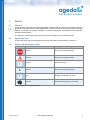
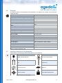
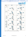
Bevel Gearboxes - Operating Instructions Content 1. Details ........................................................................................................................................................................... 4 1.1 General ................................................................................................................................................................. 4 1.2 Applicable area ..................................................................................................................................................... 4 1.3 Safety and information signs................................................................................................................................. 4 1.4 Disposal ................................................................................................................................................................ 5 1.5 Handling instructions for packaging ...................................................................................................................... 5 1.6 Disclaimer ............................................................................................................................................................. 6 1.7 Repairs ................................................................................................................................................................. 6 2. Safety ............................................................................................................................................................................ 6 2.1 Safety fundamentals ............................................................................................................................................. 6 2.2 Intended use ......................................................................................................................................................... 7 2.3 Supplemental documentation ............................................................................................................................... 7 3. Gearbox labelling........................................................................................................................................................... 8 3.1 Order key .............................................................................................................................................................. 8 3.2 Optional equipment............................................................................................................................................... 9 4. Labelling ...................................................................................................................................................................... 10 4.1 Type plate ........................................................................................................................................................... 10 4.2 Labelling on the gearbox .................................................................................................................................... 10 5. Receiving and storage ................................................................................................................................................. 11 5.1 Receiving ............................................................................................................................................................ 11 5.2 In-plant transport................................................................................................................................................. 11 5.3 Shipping gearboxes ............................................................................................................................................ 11 6. Storing ......................................................................................................................................................................... 12 6.1 Storage up to 3 months ...................................................................................................................................... 12 6.2 Long –term storage up to max. 3 years .............................................................................................................. 12 6.2.1 Corrosion protection ................................................................................................................................... 12 6.2.2 Storage space ............................................................................................................................................ 12 6.2.3 Lighting ...................................................................................................................................................... 12 6.2.4 Temperature / humidity .............................................................................................................................. 13 6.2.5 Ozone / gases ............................................................................................................................................ 13 6.2.6 Shaft seals ................................................................................................................................................. 13 7. Painting ....................................................................................................................................................................... 13 8. Lubrication ................................................................................................................................................................... 13 9. Ventilation .................................................................................................................................................................... 13 10. Temperature / temperature measurement .............................................................................................................. 17 11. Side labelling ........................................................................................................................................................... 17 Version 03/2013 www.ageda-gmbh.com 2 12. Fastening sides ....................................................................................................................................................... 17 13. Implementation of shafts and centering .................................................................................................................. 17 14. Determining the installation position (lower side) .................................................................................................... 18 15. Drive and direction of rotation ................................................................................................................................. 18 16. Assembly ................................................................................................................................................................ 23 16.1 Assembly tool set................................................................................................................................................ 23 16.2 Preparing for assembly ....................................................................................................................................... 23 16.2.1 Checking .................................................................................................................................................... 23 16.2.2 Lubrication ................................................................................................................................................. 23 16.3 Generally applicable assembly instructions ........................................................................................................ 23 16.3.1 Requirements on the installation space ..................................................................................................... 23 16.3.2 Facilitating assembly / frictional corrosion .................................................................................................. 24 16.3.3 Fastening screws ....................................................................................................................................... 24 16.4 Shafts loads / imbalances ................................................................................................................................... 24 16.5 Assembly of accessories .................................................................................................................................... 24 16.6 Assembly of flange connections ......................................................................................................................... 25 16.6.1 Smooth rotation of the shaft end ................................................................................................................ 25 16.6.2 Coaxial alignment of the flange centering .................................................................................................. 25 16.6.3 Axial runout between motor shaft and flange centering coaxial form ......................................................... 25 16.7 Assembly of slip-on gear mechanisms ............................................................................................................... 26 16.8 Shaft - hub connections with shrunk-on discs ..................................................................................................... 26 16.8.1 Assembly shaft hub connections with shrunk-on discs .............................................................................. 26 16.8.2 Disassembly shaft hub connections with shrunk-on discs.......................................................................... 27 16.9 Gearbox mounting arrangement ......................................................................................................................... 27 16.10 Motor attachment ........................................................................................................................................... 27 16.11 Motor attachment using jaw-type couplings.................................................................................................... 28 16.11.1 Assembly of couplings to clamping hub on the motor shaft ................................................................... 29 16.11.2 Assembly of jaw-type couplings to tension ring hubs on the motor shaft ............................................... 29 16.12 Installation of geared motors .......................................................................................................................... 30 16.13 Motor safeguards ........................................................................................................................................... 30 17. Commissioning........................................................................................................................................................ 31 18. Test run ................................................................................................................................................................... 31 19. Maintenance............................................................................................................................................................ 31 19.1 General maintenance instructions ...................................................................................................................... 31 19.2 Opening and assembling a gearbox ................................................................................................................... 32 19.3 Maintaining the oil levels ..................................................................................................................................... 32 19.4 Replace bearings ................................................................................................................................................ 33 19.5 Replace the radial shaft seal rings ...................................................................................................................... 34 19.6 Checking the couplings....................................................................................................................................... 34 20. Malfunctions ............................................................................................................................................................ 34 Version 03/2013 www.ageda-gmbh.com 3 1. Details 1.1 General i These operating instructions along with applicable regulations form the basis for the proper handling of gearboxes and geared motors from ageda GmbH. These instructions must be observed to exclude hazards for people and property damage, to maintain guaranteed characteristics and guarantee possible warranty claims. The manual is a part of the product and must be kept accessible in its immediate vicinity. 1.2 Applicable area These instructions apply to bevel gearboxes whose start code (first three letters) contain a K. 1.3 Safety and information signs Icon Definition Consequences of disregard Danger! personal or property damage Warning! personal or property damage ! Caution! small risk of injury A Caution! small risk of property damage Note handling, conservation of value Disposal environmental pollution, fire hazard i Table 1: Safety and information signs Version 03/2013 www.ageda-gmbh.com 4 1.4 Disposal For disposal, observe local guidelines and ordinances. This applies to oil, grease, and components coated with them. Component Material Standard housing Grey cast iron Lightweight construction gearbox housing Aluminum Cover, neck, from size K120 Grey cast iron Cover, neck K065/ K090 Steel Motor flange, adapter sleeve Aluminum Shafts, gears, parallel keys, screws, bearings, Steel discs Shaft ring seals, screw caps, rubber elements Elastomer with steel Spacer discs Aluminum, plastic Couplings Aluminum Coupling stars, O-ring seals Elastomer Gear oil (CLP, PG) Polyethylene glycol Gear oil (PAO) Poly-alpha-olefin Gear grease Mineral oil, hydrocarbon, polyurea, lithium soap Component Material Ventilation filter Plastic, steel Ventilation valve Copper Oil sight glass Plastic or aluminum + glass / plastic Screw caps Steel, plastic Cooling coils Copper, epoxide Base coat Etch primer Colour Table 2: Gearbox materials used 1.5 Epoxy resin, standard, polyurethane Handling instructions for packaging Please observe the following symbols during packing and unpacking: Icon Definition Icon Definition A Fragile, handle with care Do not use hand hooks Top Fasten here Protect from heat Keep dry Center of gravity Permissible stacking load Table 3: Handling instructions for packaging Version 03/2013 www.ageda-gmbh.com 5 1.6 i 1.7 i Disclaimer ageda GmbH assumes no liability for any personal or property damage that arises from failure to follow the operating instructions. Liability for defects is similarly excluded in the case of failing to follow the operating instructions. Repairs For safety reasons, we recommend that ageda GmbH performs all repairs. 2. Safety 2.1 Safety fundamentals Mechanical work must be performed only by authorised and specialised personnel who have completed mechanical or mechatronic training, and have read and understood these operating instructions: System commissioning / start-up Installation of customer provided safety devices Storing Assembly of the gearbox Assembly of motors, couplings or other drive elements Transport Servicing and maintenance Electrical work on current carrying machine parts or devices must be performed only by authorised and specialised personnel who are electricians, or have completed mechatronic training, and have read and understood these operating instructions. Work, such as transport, storage, painting, operating and disposal, must be performed only by authorised and specialised personnel who have completed appropriate training, and have read and understood these operating instructions. Protective clothing must be worn during all work. Before performing any work on drive units, ensure that the drive train is stopped and that the drive train / motor is secured against unintentional switching on! (Remove safeguarding and attach warning signs). Gearboxes can become extremely hot during operation and must be cooled to a temperature of at least 30 °C (86°F) before starting any work. If the exterior has cooled, the lubricant in the interior of the gearbox can have substantially higher temperatures! Exposed parallel keys must be removed before start-up, or must be secured against unintentional loosening. Drive elements mounted on the shafts must be secured in their bearing against loosening. Ensure that no loose extraneous parts come into contact with rotating components during operation. Seals must be handled with extreme caution. Oil leaks can lead to the failure of the gearbox and depending on the application can possibly represent a high safety risk. Attached motors, in the case of insufficient protection, can have freely accessible moving parts or live parts. Inputs with a unit weight > 15 kg must be moved using suitable load carrying equipment. No additional loads are to be attached to the gearbox during transport. Transport means and lifting devices must have sufficient load-bearing capacity. Do not support gearboxes at the yellow shaft protecting sleeves! Version 03/2013 www.ageda-gmbh.com 6 Damaged products must not be installed, or must be taken out of service. Upon accepting delivery, if there is any damage due to transport, immediately inform ageda GmbH and make a claim with the transport company. All rotating parts must, as a rule, be covered so that no personal or property damage can occur at any time. This also includes freely accessible shafts, shrunk-on discs, polygon shafts, spline shafts, or open hollow shafts. During and after assembly and disassembly, customer machines / components with or without gearboxes must be secured in their position against slipping or tipping. Before any work, check whether during assembly / disassembly of the gearbox locks or brakes have loosened, or weights have shifted, that could cause unintended subsequent movements. i Opening the gearbox, subsequent mechanical processing, galvanic, chemical or thermal treatment (e.g., welding) without the consent of ageda GmbH leads to loss of warranty. Any manipulation of the gearbox and its accessories by the customer is impermissible. Gearboxes must not be used as a grounding point for welding work. i The connection of different metals (e.g., stainless steel and cast iron) without a plastic intermediate layer can lead to voltage potentials, and with it to electrochemical corrosion. Always ground these gearboxes. Gearboxes must not be opened during operation, or operated while open. Tighten fastening screws to the recommended torque (see also Point 16.3.3 Fastening screws) In the case of any questions, or contradictory statements with respect to other customer / country specific instructions, contact the manufacturer. 2.2 Intended use The gearboxes and geared motors are designed for commercial use, and without Ex labelling must not be used in potentially explosive environments. The technical data on the type plate, the product related documents (catalog, drawings, data sheets) and the product catalog must be observed. Take note of any deviating performance data, lubricant information or other technical information in the order documentation, and consider the respective application case. 2.3 Supplemental documentation If a product is intended for use in a potentially explosive environment, and labelled accordingly, the operating instructions for the Ex environment must also be observed. In the case that a customer has requested delivery of ageda gearboxes combined with third party products, the documentation of these products, especially the operating instructions, must also be observed. Version 03/2013 www.ageda-gmbh.com 7 3. Gearbox labelling 3.1 Order key Figure 1: Order key Version 03/2013 www.ageda-gmbh.com 8 3.2 Optional equipment Area Toothing Abbreviation Side S1 Toothing S2 Application Application Application Application ED HT TT LP Assembly Installation Shaft Shaft BB BL VA VG x x x x Shaft Shaft Shaft KW PW HSD x x X Shaft HKW X Shaft HPW X Bearing Storing v vv AB AB Storing Storing Seal Seal Seal v vv UW 0.5 bar AS C C 3m WS X X Seal FKM X Seal Coupling PTFE KN X Coupling Coupling Coupling Motor Motor Motor Motor Motor KNN SN Ku ZF IEC SGM PGM KF Motor Brake Brake Surface TF Br BrH CV Surface CZ Surface RAL Version 03/2013 X Description low-backlash version < 10', measured at the slowest shaft low-backlash version < 6', measured at the slowest shaft duty cycle < xx % high temperature version low temperature version food / pharmaceutical industry version, stainless steel gearbox fastening bore only on side -. . . attachment strip (fastening strip) on side -. . . stainless steel shaft on side -. . . solid shaft on side -. . smooth, without groove for parallel key solid shaft with splined hub profile on side -. . . solid shaft with polygonal profile on side -. . . hollow shaft with shrunk-on disc on side . . . (A = Standard) hollow shaft with splined profile on side -. . . (B = Standard) hollow shaft with polygonal profile on side -. . . (B = Standard) reinforced output shaft bearing on side -. . . reinforced output shaft with reinforced bearing on side -. .. reinforced input shaft bearing on side -. . . reinforced input shaft with reinforced bearing on side -. . under water seal 3m WS over pressure / vacuum seal on side -. . . shaft seal rings in dust / spray protected version, on all sides, or on side -. . . shaft seal rings made of Vitom (FKM),on all sides, or on side -. . . shaft seal ring made of PTFE, on all sides, or on side -. . clamping hub without groove, motor shaft without parallel key clamping hub with groove, motor shaft with parallel key with tension ring hub, motor shaft without parallel key overload coupling, fluid coupling on side -. . . coupling flange at the motor flange with IEC motor size with spur geared motor with planetary geared motor PTC thermistor temperature sensor (PTC resistor) DIN 44 082 temperature sensor (contact) as a bimetal switch disc brake / motor brake xx Nm brake with manual release chemically nickel plated housing parts, shafts, and exterior standard parts made of stainless steel chemically nickel plated housing parts subsequently tinned, shaft and exterior standard parts made of stainless steel Custom colour, RAL xxxx www.ageda-gmbh.com 9 Area Abbreviation Documentation TS T Documentation Dok a SOND b Lubrication OA l Lubrication OLC e Ventilation EF EL Ventilation 4 Ventilation EF : Ventilation EV EB Ventilation O XX p XX t XX i XX o XX n al gearbox versions 4. Labelling 4.1 Type plate Side x x R M -A -B -AB -C -D Description type plate, information plate on side -. . . documentation custom version oil expansion tank oil sight glass (oil level control) on side -. . . ventilation filter ventilation filter with pipe bend metal ventilation filter ventilation valve aeration / deaeration valve XX on side A XX on side B XX on side AB XX on side C XX on additional neck on side D For identification, a 0.8 mm thick foil plate is applied to side E, and is legible from side D. If a neck is located on this side of the gearbox, the type plate is applied to a different side, or to the motor flange. The type plate lists basic gearbox information. It is manufactured according to the order, and is binding for the individual application. The applied bar code contains the serial number and the article number. Do not remove the type plate = loss of guarantee! i K www.ageda-gmbh.de Lubricant 090 1.0 V AB 0 A 1 a 2000 S1 /L110 K Gearbox model A Mounting orientation 090 Gearbox size 1 Grooved ball bearing 1.0 Transmission ratio [ i = 2 Tapered roller bearing V n1/n2 ] 3 Tapered roller bearing in neck AB Gearbox type [F,V,H,S,R] 4 Tapered roller bearing in output 0 Position output side A Lubrication Position of shafts on sides 2000 Low speed n2 min-1 D/E/F S1 Flank clearance S1<10‘; S2<6‘ Quantity of lubricant /L1110 Motor flange No. 1110 Figure 2: Type plate description 4.2 A Labelling on the gearbox Warning signs with yellow backgrounds must not be removed! All other information signs should only be removed if they impact the assembly or function. If it is necessary to remove an information sign, please inform us for consideration with subsequent orders. Version 03/2013 www.ageda-gmbh.com 10 Icon Definition Caution! Hot surface Before starting work, cool to approx. 30°C Icon Definition Oil dipstick Caution! Injury due to rotating parts. Stop the drive before starting work Ventilation screw Mounting orientation Observe to avoid personal or property damage Preferred direction of rotation Ventilation filter Gearbox side Oil cooler, inlet flow Oil filling plug Oil cooler, return flow Oil drain plug Temperature sensor Oil level control Explosion-proof equipment Relubrication point Table 5: Labelling on the gearbox 5. Receiving and storage 5.1 Receiving i 5.2 After receiving the delivery: Inspect the packaging for possible damage. Immediately inform ageda GmbH and the transport company in the case of damaged packaging or goods. The operational capability and assessment of the damage must be made by a qualified professional. If necessary, consult with ageda GmbH. In-plant transport General instructions must be observed during in-plant transfers, and damage to the gearbox must be avoided. Gearboxes must not be carried at the yellow shaft protective sleeves, because these sleeves can easily slip off from the lubricated shafts. Drives with a unit weight > 15 kg must be moved using appropriate load carrying equipment. No additional loads are to be attached to the gearbox during transport. Only sufficiently sized transport and lifting means that have been tested for safety are to be used as intended. Avoid pulling at an angle. In the case of transport using a pallet, secure against slippage. The weight of the gearboxes is listed in the transport documentation. Observe the center of gravity. Standing under swaying loads is dangerous! Secure hazardous zones. In the case of transport, already installed ventilation filters / ventilation valves are to be exchanged for a screw plug DIN 906 (conical) with PTFE sealing tape or screw plug DIN 908 with O-ring seal. In the case of leaking oil, spread suitable absorbent material, and secure area against entry. Depending on the quantity of oil, do not operate the gearbox. A fall from a great height can lead to damage in or at the gearbox, and lead to potential danger. Damaged gearboxes must not be used. 5.3 i Shipping gearboxes Ventilation filters / valves are to be removed when the gearbox is cool, and sealed as described Version 03/2013 www.ageda-gmbh.com 11 in the paragraph above. Inspect the gearbox's shaft seal rings, sealing caps and oil screw plugs for tightness Wrap the gearbox in film to protect the packaging from sweat oil Provide shafts and function surfaces that are not protected against corrosion - excluding aluminum flanges - with sufficient corrosion protection and put on shaft protection sleeves. Ensure a stable and generous outer packaging and padding. 6. Storing 6.1 Storage up to 3 months Improper storage can lead to personal or property damage. A 6.2 A 6.2.1 A A 6.2.2 The following must be observed during temporary storage of the gearbox: Dry, dust-free, vibration-free, and reasonably ventilated storage room Protected from the elements, environmental temperature of 5°C (41°F) < T < 60°C (140°F), < 50% relative humidity Storage away from solvents and solvent vapours Do not wrap gearbox in film containing plasticizers Avoid short-term and large temperature fluctuations Placement correctly fitted to shape and installation position Retain the operating instructions with the gearbox Screw in the ventilation filter (if required) only immediately before placing gearbox into operation, as long as the storage temperature of 50°C (122°F) is not exceeded Protect against gnawing rodents, and in the tropics, protect against insect infestation In an ideal storage room, the storage can be extended up to 6 months. Long –term storage up to max. 3 years Along with the measures named above, the shaft seals necessitate special storage requirements. In the case of storage of more than one year, the service life of the shaft seal rings is reduced for grease lubricated bearings (gearboxes for installation positions A, B, D or G). Corrosion protection Outside Provide shafts and functional surfaces that are not protected against corrosion - excluding aluminum flanges - with sufficient corrosion protection and renew if necessary Paint the housing as far as possible, a base coat is not sufficient Refinish joints before storing Inside Fill gearboxes with the VCI additive (e.g., Anticorit VCI UNI IP-40, Fuchs Lubritec Company; www.fuchs-lubritech.com), and replace already mounted ventilation filter / valves with screw plugs. Follow the instructions from the VCI manufacturer! alternatively: Fill gearbox up to the edge with oil (avoid mixing types of oil) Turn the gearbox regularly approx. every 3 month, and turn the shafts several times Storage space The storage space should be vibration-free, closed, cool, dry, sufficiently ventilated (no drafts) protected from insect infestation and gnawing rodents 6.2.3 Lighting The following must be avoided: direct exposure to sunlight Version 03/2013 www.ageda-gmbh.com 12 6.2.4 Temperature / humidity 6.2.5 artificial light with a high percentage of ultraviolet light ultraviolet / fluorescent light sources mercury lamps ideal storage temperature +15°C to +25°C (Limits: +5°C to +30°C) keep temperature as constant as possible, avoid short-term fluctuations keep at least one meter from heat radiators, no drafts humidity < 50 % Ozone / gases Over the long term, avoid the following in the direct vicinity: ozone and exhaust gases solvent fumes, petrol, chemicals, acids, disinfectants, rubber solvents strong electrical discharges, formation of sparks (electrical motors) 6.2.6 Shaft seals 7. grease shaft seals with suitable grease avoid damage to the seal lips and the shaft seat before start-up, check all seals for dryness and cracks, exchange if necessary Painting With subsequent painting, cover the shaft seals, type plate and ventilation filter to protect them from solvent-containing substances and paint. 8. Lubrication A 9. All standard gearboxes have an immersion lubrication and are filled corresponding to our lubrication table (see table 8). The basic data of the lubricant and the quantity of the lubricant are located on the type plate. If the gearbox was ordered without lubricant, it must be filled before storing or start-up with the prescribed quality and quantity of lubricant corresponding to the intended installation position and speed. In the standard case, the gearboxes are maintenance free. In the case of high demands on the service life or reliability, we recommend performing the first oil change after 500 hours of operation, and then after 15,000 hours. Avoid mixing types of oil. Ventilation Gearboxes can become extremely hot due to the high power throughput and small convection surfaces. Danger of burns! A For pressure compensation, gearboxes with an operating temperature of > 50°C, or in the case of extreme temperature fluctuations, are to be provided with ventilation / aeration. This can be provided optionally on the side by means of pipe elbows screwed into the gearbox. For this purpose, a screw plug above the oil level, as far away from the gears as possible, is to be unscrewed, and replaced by the specially supplied ventilation filter. Under unfavourable operating conditions (installation position, speed, gearbox temperature), oil / oil foam can leak out of the ventilation filter. If this occurs, the drive is to be taken out of operation, high losses of oil are to be replenished and back-up storage containers are to be installed in front of the filter. To ensure that a sufficient air exchange is possible, the operator must protect the ventilation from excessive contamination and impermissible deposits. If no ventilation / aeration is used or possible, despite high operating temperatures, the shaft seals can wear out prematurely. The resulting loss of oil can lead to personal or property damage. ageda GmbH assumes no liability in this case. During assembly work, do not permit any objects to fall into the gearbox, and do not allow any oil to leak. i The reference values for the use of ventilation for an ambient temperature of 20°C (68°F) are listed in the following table, labelled with E. Version 03/2013 www.ageda-gmbh.com 13 Duty cycle 100 % / h Rotational speed -1 n 2 [min ] 400 500 600 700 800 900 1000 1100 1200 1300 1400 1500 1600 1700 1800 1900 2000 2100 2200 2300 2400 2500 3000 Installation size K065 460 460 460 460 460 460 460 460 460 220 220 220 220 220 220 220 220 220 220 220 220 150 150 K090 460 460 460 220 220 220 220 220 220 150 150 150 150 150 150 150 150 150 150 E 150 E 150 E 68 E 68 K120 460 460 460 220 220 220 220 220 150 150 150 150 150 150 150 E 150 E 150 E 150 E 68 E 68 E 68 E 68 E 68 K140 460 460 220 220 220 220 150 150 150 150 150 E 150 E 150 E 68 E 68 E 68 E 68 E 68 E 68 E 68 E 68 E 68 E 68 K160 460 220 220 220 220 150 150 150 150 E 150 E 150 E 68 E 68 E 68 E 68 E 68 E 68 E 68 E 68 E 68 E 68 E 68 E 68 K200 220 220 150 150 150 150 E 150 E 150 E 68 E 68 E 68 E 68 E 68 E 68 E 68 E 68 E 68 E 68 E 68 E 68 E 68 E 68 E 68 K260 220 150 150 150 E 150 E 68 E 68 E 68 E 68 E 68 E 68 E 68 E 68 E 68 E 68 E 68 E 68 E 68 E 68 E 68 E 68 E 68 E 68 K160 460 460 220 220 220 220 220 220 220 150 150 150 150 150 150 150 150 150 68 68 E 68 E 68 E 68 E 68 E 68 E 68 E 68 K200 460 220 220 220 220 220 150 150 150 150 150 150 150 150 68 68 68 E 68 E 68 E 68 E 68 E 68 E 68 E 68 E 68 E 68 E 68 K260 220 220 220 220 150 150 150 150 150 150 150 150 68 68 68 E 68 E 68 E 68 E 68 E 68 E 68 E 68 E 68 E 68 E 68 E 68 E 68 Table 6: Ventilation with a duty cycle 100 % / h Duty cycle 50 % / h Rotational speed -1 n 2 [min ] 400 500 600 700 800 900 1000 1100 1200 1300 1400 1500 1600 1700 1800 1900 2000 2100 2200 2300 2400 2500 2600 2700 2800 2900 3000 Installation size K065 460 460 460 460 460 460 460 460 460 460 460 460 460 220 220 220 220 220 220 220 220 220 220 220 220 220 220 K090 460 460 460 460 460 460 460 220 220 220 220 220 220 220 220 150 150 150 150 150 150 150 150 150 150 150 150 K120 460 460 460 460 460 460 220 220 220 220 220 220 220 220 150 150 150 150 150 150 150 150 150 150 150 E 150 E 68 K140 460 460 460 460 220 220 220 220 220 220 220 150 150 150 150 150 150 150 150 150 150 150 68 E 68 E 68 E 68 E 68 Table 7: Ventilation with a duty cycle 50% / h Version 03/2013 www.ageda-gmbh.com 14 Tabe 8: Lubrication Version 03/2013 www.ageda-gmbh.com 15 288-352 198-242 135-165 414-506 ISO VG 320 ISO VG 220 ISO VG 150 ISO VG 460 ISO VG 100 (Polyglykole) CLP-PG Food Grade Fette / Fats Fette / Fats CLP Bio-degrable gear oil Biologisch abbaubare Getriebeöle 3 00 2 00 K 3 N-30 KHC 2 K-30 GHC 00 K-30 2 KP 2 K-30 GP 00 K-30 NLGI-class NLGI-Klasse Kennzeichnung DIN 51818 61-75 ISO VG 68 DIN 51825 90-110 ISO VG 100 Designation 135-165 414-506 ISO VG 460 ISO VG 150 61-75 ISO VG 68 Hydraulic oil 198-242 29-35 ISO VG 32 ISO VG 220 61-75 ISO VG 68 Food Grade Hydrauliköle (USDA-H1) CLP 135-165 198-242 ISO VG 220 ISO VG 150 414-506 29-35 ISO VG 460 ISO VG 32 61-75 90-110 135-165 Gear oil with NSF-approval HLP Food Grade Getriebeöle mit NSF-Freigabe Hydraulic oil Hydrauliköle ISO VG 150 Synthetic gearoil ISO VG 68 ISO VG 220 Synthetische Getriebeöle (PAO) CLP-HC Synthetic gearoil 198-242 414-506 ISO VG 460 Synthetische Getriebeöle mm²/s bei 40°C Designation Lubricant Viscosity Viskosität Kennzeichnung Schmierstoff Fliessfett N Aralub HLP 2 Aral Vitam GF 32 Aral Degol GS 460 Aral Degol GS 220 Aral Degol GS 150 Aral Degol PAS 320 Aral Degol PAS 220 CLS Grease Longtime PD 00 Obeen UF 00 Obeen UF 2 Olista Longtime 3 Energrease LS-EP 00 Spheerol EPL 2 Longtime PD 2 Tribol BioTop 1418/220 Optileb HY 68 Optileb HY 32 Optileb GT 100 (PAO) Optileb GT 220 (PAO) Optileb GT 320 (PAO) Optileb GT 460 (PAO) Hyspin AWS 32 Alphasyn PG 150 Alphasyn PG 220 Alphasyn PG 460 Alphasyn EP 460 Optigear Synthetic X 460 Alphasyn EP 320 Optigear Synthetic X 320 Alphasyn EP 220 Optigear Synthetic X 220 Alphasyn EP 150 Optigear Synthetic X 150 HIGH-LUB L 3 Energrease LS-EP 2 Biohyd SE-S 68 (HLP) Energol HLP-HM 32 Bartran 32 BP Enersyn SG-XP 100 Enersyn EP-XF 320 Enersyn HTX 220 Enersyn EP-XF 220 Enersyn HTX 150 Enersyn EP-XF 150 BP Enersyn SG-XP 460 BP Enersyn SG-XP 220 Enersyn HTX 460 Enersyn EP-XF 460 BECHEM-RHUS LIC-00 HIGH-LUB LT 2 EP UWS-Getriebeöl GEP 220 UWS-Getriebeöl GEP 150 BERUSYNTH 68 H1 BERUSYNTH 460 H1 BERUSYNTH 220 H1 BERUSYNTH 150 H1 BERUSYNTH 68 H1 STAROIL Nr. 32 BERUSYNTH GP 460 BERUSYNTH GP 320 BERUSYNTH GP 220 BERUSYNTH GP 150 BERUSYNTH EP 460 BERUSYNTH EP 220 BERUSYNTH EP 150 BERUSYNTH EP 100 LAGERMEISTER 3000 Plus URETHYN 160 (KP2/3P-20) GEARMASTER LI 400 GERALYN 2 GERALYN P2 GERALYN 00 (GF00G-20) GEARMASTER ECO 460 GEARMASTER ECO 220 GEARMASTER ECO 150 GEARMASTER ECO 100 GEARMASTER ECO 68 RENOLIN B10 GEARMASTER SYN 460 GEARMASTER SYN 320 GEARMASTER SYN 220 GEARMASTER SYN 150 GEARMASTER PGP460 GEARMASTER PGP 220 GEARMASTER PGP 150 GEARMASTER PPG 100 GEARMASTER PGP 68 Klüberplex BEM 41-132 Klüberplex BE 31-222 (KP2/3N-10) Klüberplex GE 11-680 Klübersynth UH1 64-62 Klübersynth UH1 14-1600 Klüberbio CA 2-100 Klüberbio CA 2-460 Klübersynth GEM 2-220 Klüberfood 4 NH1-32 Klüberfood 4 NH1-68 Klüberoil 4 UH1-68 N (CLP HC) Klüberoil 4 UH1-460 N (CLP HC) Klübersynth UH1 6-460 (CLP PG) Klüberoil 4 UH1-220 N (CLP HC) Klübersynth UH1 6-220 (CLP PG) Klüberoil 4 UH1-150 N (CLP HC) Klübersynth UH1 6-150 (CLP PG) LAMORA HLP 32 Klübersynth GEM 4-460N Klübersynth GEM 4-320N Klübersynth GEM 4-220N Klübersynth GEM 4-150N Klübersynth GH 6-460 Klübersynth GH 6-220 Klübersynth GH 6-150 Klübersynth GH 6-100 Mobilux EP 2 Mobilux EP 3 Mobilux EP004 Mobilgrease FM 462 Mobilgrease FM 007 Mobil DTE FM 32 Mobil DTE FM 68 Mobil DTE FM 460 Mobil DTE FM 220 Mobil DTE FM 150 Mobil DTE 24 Mobilgear SHC XMP 460 Mobilgear SHC XMP 320 Mobilgear SHC XMP 220 Mobilgear SHC XMP 150 Mobil Glygoyle 460 Mobil Glygoyle 220 Mobil Glygoyle 22 Mobil Glygoyle 11 Obeen UF 00 Obeen UF 2 Longtime PD 00 Obeen UF 3 Longtime PD 2 Hydo BS 68 Optisynt BS 460 Optisynt BS 220 Optileb HY 32 Optleb HY 68 Optileb GT 460 Optileb GT 220 Optileb GT 150 Hydo 32 Optflex A 460 Optiflex A 220 Optiflex A 150 Optiflex A 100 Tribol 943AW/32 Tribol 800/100 Tribol 800/150 Tribol 800/220 Tribol 800/460 Shell Cassida RLS 2 Shell Alvania RL 3 Shell Retinax EPL2 Shell Naturelle Gear Fluid EP 460 Shell Naturelle Gear Fluid EP 220 Shell Naturelle Gear Fluid EP 150 Tribol 3030/100 Tribol BioTop 1418/460 Tribol BioTop 1418/220 Tribol BioTop 1418/150 Shell Cassida HF 68 Tribol (1840/68) Shell Cassida HF 32 Tribol (1840/32) Shell Cassida HF 68 Shell Cassida GL 150 Shell Cassida GL 220 Tribol (1810/220) Shell Cassida GL 460 Tribol (1810/460) Shell Tellus 32 Shell Tellus S 32 Shell Tivela S 150 Shell Tivela S 220 Shell Tivela S 460 Shell Omala HD 150 Tribol 1510/150 Optigear Shell Omala HD 460 Tribol 1510/460 Synthetic A 460 Optigear Shell Omala HD 320 Tribol 1510/320 Synthetic A 320 Optigear Shell Omala HD 220 Tribol 1510/220 Synthetic A 220 Figure 3: Position of the ventilation Figure 4: Alternate positions of the ventilation Position of the ventilation Size Thread a mm D mm h1 mm h2 mm L1 mm L2 mm 090 1/4'' 15 27 21 50 31 21 120 3/8'' 15 32 25 55 36 24 140 3/8'' 15 32 25 55 40 28 160 1/2'' 15 32 25 59 52 37 200 1/2'' 15 32 25 59 54 37 32 25 59 62 40 260 1/2'' 15 Table 9: Dimensions of the ventilation Version 03/2013 www.ageda-gmbh.com 16 10. Temperature / temperature measurement The gearboxes were designed for ambient temperatures of -10 to +30°C (14 to 86°F). Large fluctuations or exceeding the limit temperature of 90°C (194°F), must be discussed with ageda GmbH. Before performing any work, the drive must be cooled at least to a temperature of 30 °C (86°F). If the exterior has cooled, the lubricant in the interior of the gearbox can have substantially higher temperatures! Danger of burns! The measurement device used for checking the gearbox temperature must be capable of measuring over the expected measurement range of at least 10°C to 130°C (+/- 4K), and capable of measuring the temperatures of the housing, oil and air. Temperature measurement procedure: 1. Place the gearbox into operation (follow the instructions) 2. Depending on the speed, switch off the drive after approximately 20 to 90 minutes, and secure against unintended starting 3. Determine the point with the highest temperature (shafts in the area of the seal, bearing points in the neck or covers, or at the locations thermally loaded from outside) 4. Record the measured values and locations 5. Measure the gearbox temperatures under maximum production conditions (load, speed, temperature...) every 10 minutes according to the same procedure, until the gearbox temperature increases less than 2 K/h (final heating) 6. Record and save the temperature values and associated points (mark, if necessary) 7. Measure the ambient temperature under operating conditions i 11. i 12. For long term tests, the gearbox can be provided with a temperature measuring adhesive strip. The determined temperature values can be used, with consideration of the ambient temperature, for assessing the operating state of the gearbox. Side labelling The gearbox sides are labelled with the letters A to F. Definition: A = "Drive", crown wheel: low speed + high torque* C = "Drive", bevel pinion: high speed + low torque* * for i> 1:1 Fastening sides It is possible to fasten standard gearboxes on any side. The preferred fastening sides are the corner bores present in the square shape, because these permit direct connection to the base housing (except for K065 side B). In addition, the attachment above the type plate that is more than 0.08 mm thick is also possible. 13. Implementation of shafts and centering Solid shafts o Fit ISO j6 o Parallel key according to DIN 6885/1 Form A o Centering D according to DIN 332 Hollow shafts o Fit ISO H7 o Parallel key groove DIN 6885/1 o From bore diameters of 32 mm, additional locking ring insert Version 03/2013 www.ageda-gmbh.com 17 o This should facilitate the disassembly of larger shafts, and can also be to secure bearings of components Hollow shafts for shrunk-on discs o Under the shrunk-on discs - Fit ISO H6 (countershaft ISO j6) o Under the guide bushings - Fit ISO H7 (countershaft ISO h6) Centerings o Exterior centerings - Fit ISO f7 o Internal motor centering - Fit ISO H7 14. i i Determining the installation position (lower side) The lower gearbox side is specified on the type plate as an installation position. Installation positions labelled with "G", have seals on all sides, and can be mounted in any installation position Installation positions labelled with "W" are for changing installation positions, or positions inclined at a predetermined angle Specific gearboxes are provided with additional adhesive decals for the positional orientation (see Figure 6) Figure 5: Installation positions 15. i Drive and direction of rotation The drive of the gearboxes is possible from every drive shaft in both directions of rotation. Figure 6: Position For pinion shafts with Orientation K-series type F, V, H, S: pinion shaft at side C turning clockwise K-series type R: pinion shaft at side A turning clockwise K-series type R: pinion shaft at side A turning counterclockwise all axial forces are to be directed outwards, and as result the sound level is reduced by up to 2 dB(A). The direction of rotation of the individual shafts can be checked by manually rotating the drive shaft. Version 03/2013 www.ageda-gmbh.com 18 Figure 7: Direction of rotation type F (solid shaft with single bearings) Version 03/2013 www.ageda-gmbh.com 19 Figure 8: Direction of rotation type V (solid shaft) Version 03/2013 www.ageda-gmbh.com 20 Figure 9: Direction of rotation type S (hollow shaft with shrunk-on disc) / type H (hollow shaft) Version 03/2013 www.ageda-gmbh.com 21 Figure 10: Direction of rotation type R (pinion shaft) Version 03/2013 www.ageda-gmbh.com 22 16. Assembly Follow safety instructions listed under point 2! 16.1 Assembly tool set i Spanner corresponding to the selected fastening screws Torque spanner Extractor / retractor Shims / spacers PTFE paste or spray Measurement gauge with stand (scale 0.01 mm) depending on model size Machine spirit level and try square depending on installation case Heating ovens, heating plates, device for induction heating Equipment is not a component of the scope of delivery. 16.2 Preparing for assembly 16.2.1 Checking i i i 16.2.2 i i i Compare the type of gearbox / serial number / article description Check the gearbox for transport / storage damage, particularly for leaks; damaged drives must not be installed Remove shaft protective caps or carefully peel shaft protective paint manually. Do not treat the seals with paint, trichloroethylene, carbon tetrachloride, radioactive materials, hydrocarbons, solvents, radioactive substances or other aggressive chemicals Seal lips on the shaft seals must not be damaged Seals with cuts, cracks, wear, hardening, softening, tackiness, discolouration, loose positioning or porous locations must be exchanged. In this case, please consult with us. Damage to the shafts in the area of the seal lips in form of scratches, contamination or rust deposits is not permissible Check the free accessibility of the fastening bores, and remove dirt or residue form subsequent painting, if necessary Lubrication Gearboxes arrive filled with oil, ready for operation Compensate for lost oil After long storage times of more than two years, drain the oil (specification of the oil manufacturer) and refill with the type and quantity of oil corresponding to the type plate If the oil is filled into the gearbox up to the brim, reduce it to the prescribed quantity If you are changing the type of oil, possibly flush with solvent-free media (lower viscosity oil, petroleum) Oil levels that are too high increase the gearbox temperature, and thus reduce the service life of the seals Dispose of used oil properly 16.3 Generally applicable assembly instructions 16.3.1 Requirements on the installation space i The installation space should allow sufficient air cooling with at least 10K below the maximally permissible ambient temperature Cooling using extremely cold air can lead to the formation of condensation and water accumulation in the oil, and must be avoided In the case of a high degree of contamination, use shaft seals with bar lip Version 03/2013 www.ageda-gmbh.com 23 i 16.3.2 i A 16.3.3 For coating or covering of the gearbox, consult with ageda GmbH Keep the environment free of high energy radiation Protect from solar radiation Gearboxes are to be fastened only in the ordered installation position on a suitable foundation that is free of warping and stress Apply suitable corrosion protection measures for installations in moist spaces or outdoors. Facilitating assembly / frictional corrosion If the machine parts are to be greased, do not use any Molykote, oil or grease containing molybdenum disulfide (MoS2) or other high pressure additives. Light machine oil is a better choice (e.g., Castrol 4-in-1, or Klüber Quitsch Ex). For facilitating assembly and for avoiding frictional corrosion, a suitable separating agent is to be used at all shaft / hub connections (e.g., PTEF / Teflon spray by OPN Chemie Company 57290 Neukirchen, Germany). Do not use beneath a shrunk-on disc seat! Fastening screws Check all fastening screws for sufficient screw-in depth of the threaded bores and avoid warping. Keep contact surfaces and screws free of grease. The tightening torques depend on the respective screw application. If no tightening torque is specified, use the tightening torques in the following table: 16.4 Screw / Nut (screw grade 8.8) Tightening torque M5 6.2 Nm M6 10.5 Nm M8 25.5 Nm M10 50 Nm M12 85 Nm M16 210 Nm M20 410 Nm Table 10: Tightening torques for the fastening screws Shafts loads / imbalances Radial and axial shaft loads must lie below the catalog specifications. In the case of assembling belt drives and chain drives, their preload must be checked. To keep the bearing loads as low as possible, belts, chains and toothed gears must be installed as close to the housing as possible. Imbalances due to accessories are not permissible. 16.5 Assembly of accessories For avoiding bearing damage, accessories such as couplings, sprocket wheels, etc. are not to be attached to the shaft by striking with a hammer, or other impermissibly high axial forces (bearing damage) Accessories should be wound onto the shaft according to the drawing In addition, accessories can be heated briefly to a max. of 100 °C. An external heating of > 90°C of the gearbox seals and of the oil is not permissible [1] shaft end [2] axial bearing [3] coupling hub [4] hub Figure 11: Assembly of components Version 03/2013 unfavourable assembly www.ageda-gmbh.com correct assembly 24 16.6 A 16.6.1 Assembly of flange connections Carefully align shaft and flange connections Try to attain the reduced tolerance range from Table 10 (excerpt from DIN 42955), and not to exceed the standard tolerance range; additional details can be found in DIN 42955 Use elastic couplings to equalize manufacturing / assembly inaccuracies, and compensate their adjustment possibilities with the actual displacements Statically over-determined supports are to be avoided or adjusted very accurately Avoid overloading all screw connections, also between housings, covers, necks and lanterns Smooth rotation of the shaft end To avoid bearing / coupling damage, before assembling check the motor shaft for smooth rotation (see Figure 12 / Image 1) and the motor flange for coaxial alignment and axial runout. 16.6.2 Coaxial alignment of the flange centering Diameter of the shaft end d Balanced rotation tolerance at the center of the shaft N (normal) R (reduced) up to 10 0.03 0.015 over 10 to 18 0.035 0.018 over 18 to 30 0.04 0.021 over 30 to 50 0.05 0.025 over 50 to 80 0.06 Table 11: Balanced rotation tolerance at the center of the shaft 0.030 Figure 12: Avoidance of coupling damage 16.6.3 Axial runout between motor shaft and flange centering coaxial form Mounting flange Centering diameter b1 Coaxial alignment and axial runout tolerance N (normal) R (reduced) 40 to 100 0.08 0.04 over 100 to 230 0.10 0.05 over 230 to 450 0.125 Table 12: Coaxial alignment and axial runout tolerance 0.063 Position the motor shaft pointing vertically upwards, in order to exclude an error from the axial play of the bearing and the force of gravity. (see Figure 12 / Image 2 - 3). For measuring the axial runout, let the gauge run on a radius of one quarter of the sum of the flange outer diameter, the hole circle diameter and the screw bore hole. To exclude an axial shift of the shaft, the stand for the gauge is moved for a second measurement by 180° onto the opposite side of the shaft, and the measurement is repeated. An average value is formed from the two measurements. We recommend adhering to the reduced values. Version 03/2013 www.ageda-gmbh.com 25 16.7 Assembly of slip-on gear mechanisms Slip-on gear mechanisms are gears that, for instance, are placed on the pivot of a doubly mounted cylinder. To avoid warping or statically over-determined supports, the torque is absorbed by a torque support. To avoid additional forces, the torque support is to be installed on the machine side. For reducing start-up jolts, and for compensating for manufacturing tolerances, we recommend installing a rubber buffer in the fastening point at the machine frame. The support point of a torque support must be sufficiently rigid, and the threaded connection that is used is to be secured against loosening, even with observing the tightening torque (e.g., Loxeal 54-03, Loctite 242) Ensure good coaxial alignment If the gearbox is used as a second support point of a machine part, ensure a sufficient load capacity of the gearbox bearing along with the coaxial alignment. Do not impinge hollow shafts, and assemble as shown in figure 13. Disassemble hollow shafts using extracting tool, or for hollow shaft bore holes > 32 mm, according to the figure 14. Figure 13: Assembly of a slip-on gear mechanism 16.8 Figure 14: Disassembly of a slip-on gear mechanism Shaft - hub connections with shrunk-on discs Information for the layout of the clamping sets can be found at www.ktr.com. The clamping set used at the factory can transfer the maximum torque listed in the catalog in the case of proper design of the customer shaft. In the case of additional axial forces, please consult with us, because these forces must be calculated separately. In the case of clamping sets from another manufacturer, please contact us. Tolerance surfaces: Rz ≤ 16 µm Tolerances: The hollow shafts on the gearbox side are accepted with tolerances according to the manufacturer. Shaft diameter dw 18 - 30 [mm] Tolerance H6/j6 Table 13: Shaft seat tolerance test 16.8.1 A 31 - 50 51 - 80 81 - 500 H6/h6 H6/g6 H7/g6 Assembly shaft hub connections with shrunk-on discs The customer side machine shaft should be sufficiently dimensioned and have a minimum yield strength of ≥ 320 N/mm² Clean contaminated or used clamping sets The shrunk-on discs sets should not be disassembled if possible Disassemble only if absolutely necessary, lightly grease tapered surfaces and contact surfaces of the screw heads (e.g., Castrol 4-in-1 or Klüber Quitsch Ex) Check shaft seat for the tolerance according to Table 12 Contact surfaces between the hollow shaft interior and inserted shaft must be free of grease in the clamping region Slightly loosen the tensioning screws, do not remove them, and slightly tighten them by hand, until there is no play between the outer ring and inner ring Never tighten the tensioning screws without the inserted solid shaft Slide the clamping set onto the hollow shaft Version 03/2013 www.ageda-gmbh.com 26 Install the shaft so that the clamping region beneath the shrunk-on disc is completely utilised and supports the bronze bushing in the complete length, it must be easy to insert the shaft Uniformly tighten the tensioning screws, increasing the tightening torque in a step-wise manner The tightening torque, found in Table 13, should be present for all screws Screw size M M5 M6 Tightening torque TA 4 12 [Nm] Table 14: Tightening torques for the screw sizes M8 M10 M12 M16 M20 30 59 100 250 490 Check for uniform distribution of the clearance between the outer ring of the shrunk-on disc Mark the position of solid shaft and hollow shaft to each other using a felt-tip pen / scriber, so that slippage under load during test runs can be detected Freely accessible clamping sets are to be protected from access or parts falling in! Figure 15: Shrunk-on disc 16.8.2 A 16.9 A A i Disassembly shaft hub connections with shrunk-on discs First, loosen all tensioning screws by 1/4 screw rotation, proceeding in a circular manner Then further unscrew the tensioning screws (but not completely) Screw the screws into the pressure-test threading up to the stop Tighten all forcing screws uniformly until the clamping set loosens Remove the shaft from the hollow shaft and, if required, use a release tool, NEVER STRIKE!! Gearbox mounting arrangement Figure 15: The gearbox must be installed according to the prescribed installation position. A Shrunk-on disc change of the installation position is only permissible with the consent of ageda GmbH and with completed modification of the lubricant quantity and ventilation position. Attachment surface, to which the gearbox is fastened, must be kept clean, resistant to warping, and with low vibrations For the smoothness of the attachment flange, see DIN ISO 2768-2 (Class K) Align the shaft axes and shaft heights to avoid bearing damage and shaft breakage (use shims for adjusting) Observe the limit values for coupling distances, radial and angular offset for the couplings used Maximum and minimum offset Figure 16: Assembly tolerances 16.10 Axial offset Angular offset Motor attachment A Version 03/2013 Ensure that drive train and motor are load free and without current during the assembly. Clean and grease flanges, shafts and hubs at the motor and gearbox Observe the information from point 16.6 Flange connection Refinish any damage, such as compressions, on the motor shaft, the flanges, the parallel key or their groove edges www.ageda-gmbh.com 27 A i i 16.11 Adjust the length, width and height of the parallel key to the dimensions of the hub Parallel key connections must be able to be joined without resistance Observe the instructions to avoid frictional corrosion If placing outdoors, seal the flange against the penetration of humidity/water using a surface sealant (e.g., Loctite 574 or Loxeal 58-14) Place the motor or gearbox vertically using a hoist Avoid canting and hammer blows For large drives, loosen the motor brake Align the position of the parallel key/parallel key groove and the flange holes to each other, and lower motor/gearbox Before making the threaded connection, check the flange connection using a sensor (feeler) to determine if both flange surfaces are in contact over the entire circumference Tighten fastenings screws in a cross-wise sequence Motor attachment using jaw-type couplings In the ideal case, motors are connected using axial insertable shaft couplings. In this way, the start-up jolt is reduced in dynamic applications, while still permitting a low-backlash motor connection Coupling assembly (ROTEX GS): The gearbox side coupling is pre-assembled Involute spiders made of plastic (bored, without bores) Motor side coupling Clamping hub in model 2.0 (type KN, standard) or clamping hub with parallel key model 2.5 (type KNN); or tension ring hub model 6.0 (type SN) The torques that can be transmitted depend on the model of the motor shaft and its dimensions. The couplings cannot transmit the entire gearbox torque in every case, however they exceed the torques of the IEC standard motors and standard servo motors. Factors to be considered for the operating temperature, for the torsional rigidity, and for the operating ratio can be found in the KTR catalogue at www.ktr.com. If you have any questions, please consult with ageda GmbH. Tolerance surfaces: Rz ≤ 16 µm Tolerances: On the gearbox side, the hollow shafts are acepted with tolerances according to the manufacturer. Clamping hub with/without groove Tension ring hub (model 2.0 / 2.5) (model 6.0) Shaft diameter dw <55 >55 <55 >55 [mm] Tolerance H7/k6 H7/m6 H7/k6 G7/m6 Table 15: Tolerances with clamping ring and tension ring hub The jaw-type couplings used can be delivered with spiders of different shore hardness. The hardness of the elastomer star determines the extent of the maximum shaft misalignments and of the backlash. The specified misalignment values are maximum values and must not occur simultaneously. Resources for checking: gauge, straight edge, feeler gauge. Standard spider hardness [Shore] Marking [colour] 80 Sh A – GS blue 92 Sh A – GS yellow 95/98 Sh A - GS 64 Sh D - GS red green (Gr. 7 - 38) pale green (Gr. 42 - 75) Table 16: Shore hardness of the spiders Version 03/2013 www.ageda-gmbh.com 28 16.11.1 Assembly of couplings to clamping hub on the motor shaft (KN = clamping hub, KNC = clamping hub compact) Carefully degrease the coupling bore hole and the motor shaft Slightly loosen clamping screw (see Figure 14). Slide the hub onto the shaft Measure dimension A on the gearbox Figure 17 Adjust distance dimension B (from Table 17) Tighten the clamping screws to the torque specified in Table 17 Figure 17: Assembly of a servo motor Figure 18: Clamping hub 16.11.2 Assembly of jaw-type couplings to tension ring hubs on the motor shaft Carefully degrease the coupling bore hole and the motor shaft Slightly loosen tension screws and slightly remove the tension ring from hub Slide the hub onto the motor shaft Measure dimension A on the gearbox Figure 17 Adjust distance dimension B (from Table 17) Tighten the tension screws, using a cross-wise sequence, to the tightening torque listed in Table 17 , until the tightening torque is attained at all screws formula Coupling size Unit 14 19 24 28 38 42 48 symbol ROTEX GS Diameter Clamping screw DIN 912 Tightening torque Clearance Clearance ROTEX GS Compact Diameter Clamping screw DIN 912 Tightening torque Clearance Clearance ROTEX GS Spannring Diameter Clamping screw DIN 912 Tightening torque Clearance Clearance ROTEX GS Spannringnabe light Diameter Clamping screw DIN 912 Tightening torque Clearance Clearance DH mm TA s B Nm mm mm DH mm TA s B Nm mm mm DH mm TA s B Nm mm mm DH mm TA s B Nm mm mm 30* M3* 1.34* 1.5* A-1.5* 40 M6 10.5 2.0 A-2.0 55 M6 10.5 2.0 A-2.0 65 M8 25 2.5 A-2.5 80 M8 25 3.0 A-3.0 95 M10 69 3.0 A-3.0 105 M12 120 3.5 A-3.5 30 M4 2.9 1.5 A-1.5 40 M6 10 2.0 A-2.0 55 M6 10 2.0 A-2.0 65 M8 25 2.5 A-2.5 80 M10 49 3.0 A-3.0 30 M3 1.34 1.5 A-1.5 40 M4 3 2.0 A-2.0 55 M5 6 2.0 A-2.0 65 M5 6 2.5 A-2.5 80 M6 10 3.0 A-3.0 95 M8 35 3.0 A-3.0 105 M10 69 3.5 A-3.5 55 M5 7 2.0 A-2.0 65 M5 7 2.5 A-2.5 80 M6 12 3.0 A-3.0 95 M8 30 3.0 A-3.0 105 M10 59 3.5 A-3.5 *ROTEX GS miniature couplings Table 17: ROTEX® coupling sizes Version 03/2013 www.ageda-gmbh.com 29 16.12 i Installation of geared motors Along with the instructions for assembling the gearbox, and country-specific regulations, the following additional points are to be observed during the assembly of geared motors. Compare the type plate data to the order and the installation conditions: labelling, installation position, electrical connection data, power, speed, type of protection and heat class 50 Hz motors can be connected to 60 Hz network, thereby changing the voltage, torque and speed Electrical connections must be made only by specialised personnel, and must correspond to the applicable safety regulations Before commissioning, check the isolation resistance of the motor windings (at 25°C (77°F) greater than 5MΩ) Voltage and frequency fluctuations according to DIN EN 60034-1 If no motor heating block is used, use stationary heating in the case of temperatures < -10°C (14°F), in the case of large temperature fluctuations, or high air humidity In the case of air cooling, check for sufficient fresh air draft, free cooling fins, inlet and outlet openings of the fans A minimum space of at least one half of the motor diameter should be present between the fan grating and the next wall In the case of vertically upright motors with fans on top, a protective roof for the fan or other covering must be installed The cross-sectional area of the connection cables must be sufficiently dimensioned and correspond to DIN VDE 0298 / country-specific regulations Establish and check the earthing connection (near or directly on the terminal box) Cable entry points must be provided with screw connections according to DIN 46320/T1 Before connection to other machine parts, check the direction of rotation in the installed position "Clockwise" rotation of the machine: Connect phase sequence L1, L2, L3 to terminals u1, v1 and w1, as shown. For a reversed rotation, exchange any two phase connection lines. Figure 19: Motor terminal strip 16.13 i Motor safeguards If the required starting torque of the working machine is less than the nominal torque of the geared motor, the drive can be started using a direct start, if the connected mains and the connection cables permit an increased starting current. For increasing the service life of the drive in the case of frequent start procedures, a star / delta connection should be used. With the use of a delta connection, the starting current and the starting torque amount to approx. 1/3 of the values without such a connection. To avoid overloading the supply voltage, the switchover from the star to the delta connection should occur only in the proximity of the nominal motor speed. Electronic smooth starters effect a jolt-free motor start-up even with simultaneously reduced starting current. For using frequency converters and for protecting against overload, short circuits or single phase operation, the motor is to be provided with a protective switch. PTC sensors (thermistors) inserted in the motor winding are to be connected to a suitable tripping unit. Thermostats are pre-wired self-switching. Version 03/2013 www.ageda-gmbh.com 30 17. Commissioning Gearboxes can become extremely hot due to the high power throughput. There is a danger of burns. A For pressure compensation, gearboxes with an operating temperature of > 50°C (122°F), or in the case of extreme temperature fluctuations, are to be provided with ventilation. This can be provided optionally on the side by means of pipe elbows screwed into the gearbox. For this purpose, a screw plug above the oil level, as far from the gears as possible, is to be unscrewed, and replaced by the specially supplied ventilation filter. Use caution to not permit any objects to fall into the gearbox, and do not allow any oil to leak. For further transport of the gearbox, a sealed screw cap should be used. In the case of any unusual running noises, loss of lubricant, vibrations or housing temperatures > 95°C (203°F), take the drive out of operation, and consult with the factory. During commissioning, the temperature of the gearbox should correspond to the room temperature. For a gearbox with ventilation filter / valve, this should be screwed in before commissioning Before commissioning, check for the correct installation position and direction of rotation, so there is no resulting damage to the working machine. Before attaching the coupling, please check that the drive shaft can rotate uniformly in both directions, and without any hard points. Listen for any unusual noises. In the case of unusual noises, vibrations or temperatures above 90 °C, stop the drive, and immediately inform ageda GmbH. 18. Test run The test run should take place under unfavourable conditions (max. load and speed). Upon reaching the maximum gearbox temperature, note the following points: Noises (grinding, knocking, grating) Vibrations Odor, steam, or smoke Oil leaking at the shaft seals, the housing joints, the ventilation filter / valve (if required) During the test run, ensure that there is sufficient protection from rotating small parts (e.g., parallel keys), or that theses are specially secured. After completing the test run, with the cooled gearbox, check the following: Seals traces of oil fixed seating of all components clamped connections, such as couplings, shrunk-on discs, etc for slippage In the case of unusual running noises, loss of lubricant, vibrations or housing temperatures > 95°C, the drive is to be taken out of operation, and consultation with the factory is required. Check the shaft seat to the prescribed tolerance (see Table 12) 19. Maintenance 19.1 General maintenance instructions i All ageda GmbH drives are low maintenance. The scope of maintenance is limited to a regular check of the seals, running noises, operating temperatures and the free inlet of the ventilation filter, if this is necessary. i In addition, the following is to be observed: Version 03/2013 www.ageda-gmbh.com 31 Only lubricants of the same specification are to be used for supplementing or replacing lubricant. Do not use any solvents or solvent-containing substances, or other aggressive substances for cleaning the gearbox at the shaft seals. Depending on the environmental influences, the corrosion protection is to be renewed, or the paint is to be repaired. Depending on the degree of dust deposits, the ventilation filter / valves are to be replaced, by authorised personnel only. The shaft seals must be inspected regularly. In the case of excessive shaft loading, the radial or axial backlash must be checked at the shaft ends. 19.2 Opening and assembling a gearbox Opening the gearbox During opening of the gearbox, ensure that: no particles of dirt, or components, fall into the gearbox, the position of all components (particularly the shafts) is marked, and the shims and adjustment discs are not interchanged with each other. i Opening the gearbox independently voids the warranty and guarantee. Assembling the gearbox During assembly of the gearbox, ensure that: O-ring / surface seals are replaced with the same quality / dimension seals, and lubricated before the assembly. new screws with the same strength class are used, and are tightened to the appropriate torque. The screws are assembled without grease. 19.3 Maintaining the oil levels By default, bevel gearboxes are filled half full with oil. For the specification of the type of oil used in your gearbox, check the type plate. A The gearbox must be cooled before checking the oil level, and the drive and output must be decoupled. Position the gearbox in the installation position for the purpose of this test. Check oil level There are different variants to the oil level test. For gearboxes from size K090, the following variant applies: Figure 20: Screw plug on the side Check the oil level using the screw plug on the side Carefully unscrew the screw plug and measure the oil level using a test wire. Check the oil level using the screw plug on top Carefully unscrew the screw plug. Measure the oil level using a clean test stick / wire, and then hold the measuring stick / wire at the outer housing. The oil level should be half the height of the housing. Figure 21: Screw plug Checking the oil level using an elbow pipe and dip stick on top Carefully unscrew the dipstick, wipe it clean using lint-free cloth, screw the dipstick in, and then unscrew it and read the level. Version 03/2013 www.ageda-gmbh.com 32 Checking the oil level using an oil sight glass The oil level should at the center of the sight glass. A Avoid mixing oil with different specifications. The oil can be filled using the filler plug, the bore hole of the ventilation filter, the oil control bore hole, the neck of the gearbox or side B. Open bore holes must be securely closed. If the thread or the seal of the screw is damaged, exchange them. Figure 22: elbow pipe Change the oil: Place a catch basin underneath the outlet plug and carefully unscrew the outlet plug Put the gearbox down in such a way that the oil can drain out completely Check the screw and the seal. If there is any damage, exchange them Fill in the quantity of oil specified in the information from ageda GmbH, and after 15 minutes, check the oil level at the check opening Close the check opening i Oil losses indicate a defect in the sealing system. This is not always visible externally, because the oil can run into cavities between the motor and the gearbox (lantern). A minimal oil loss can occur via the ventilation filter, at the first time the gearbox reaches a maximum temperature. Check the oil level after any loss of oil. 19.3.1 Dismounting of the neck Mark the neck before dismounting Turn shafts until the keys are facing each other Unfix the screws of the neck Use the plug puller to lift the neck. Do NOT lift the neck by using a screwdriver! Remove carefully the slices between the Figure 23: neck markering housing and the neck. Let the oil drip oft o the housing. Check the oil level inside the housing. Return the slices carefully Mounting oft he neck (check the neck markering) Fix the neck by the screws (Check the torque) Figure 24: key placement 19.4 i Figure 25: plug puller Replace bearings In the case of bearing damage (temperature too high, noise, backlash, etc.), it is necessary to replace the bearings. The service life of the bearings corresponds to the relevant guidelines for industrial gearboxes. Version 03/2013 www.ageda-gmbh.com 33 19.5 i Replace the radial shaft seal rings Radial shaft seals are to be replaced, according to the type of loading due environmental influences and the temperature (highly speed dependent), only by skilled personnel or the manufacturer. Do not put new shaft seal rings on damaged shaft fittings or the same running tracks. Refinishing of the shaft fittings is to be performed on-site by the customer only with appropriate specialised technical knowledge. 19.6 i Checking the couplings The elastomer star of a jaw-type coupling (ROTEX®) is subjected to wear in the case of extreme shaft displacements or torque loading. If the star width falls below the tolerance listed in the following table, or has other damage or discolouration, the star is to be replaced by a new star of the same quality. Type 14 19/24 24/28 28/38 38/45 42/55 b 10 7 8.5 11 13 16 normal b min 7.5 5.2 6.5 8.2 9.6 12 elastomer stars of jaw-type couplings Table 18: Wear limits of the The elastomer star should be checked either after 1,000 hours of operation, or after three months at the latest. 20. Figure 26: Gear coupling Malfunctions In the case of malfunction, please have the following information on hand: Serial number and gearbox type Type of malfunction Application area of the gearbox Temporal progression of the malfunction In case of emergency, please contact ageda GmbH at our 24 hour hotline: + 49 (0) 4103 90 006 - 12 Malfunction Possible Cause Conspicuous steady running noises defective bearing Gearbox shafts moving radially or axially defective bearing Conspicuous steady running noises, depending on the engagement position of the teeth Gearbox noise with vibrations Correction bearing must be replaced; should be replaced by the manufacturer bearing must be replaced; should be replaced by the manufacturer defective gear set repair with new warranty defective coupling Gearbox noise with vibrations defective bearing Irregular running noises foreign body in the oil exchange the coupling bearing must be replaced; should be replaced by the manufacturer contact the manufacturer Smells like plastic defective coupling Replacing the coupling star Version 03/2013 www.ageda-gmbh.com 34 Smells like plastic defective shaft seal ring exchange the seal Oil leak at seal ring defective shaft seal exchange the seal Oil leak at the housing defective housing seal unfavourable combination of speed, direction of rotation, temperature, oil level, installation position multiple causes exchange housing seal Oil leak at the ventilation filter / valve Temperature increase contact the manufacturer contact the manufacturer Blocked gearbox Shafts do not rotate, or do not rotate uniformly defective gear set or bearing exchange the defective parts Shaft-hub connection is broken contact the manufacturer at or in the gearbox defective gear set, shaft broken, No torque transfer contact the manufacturer loose gear Table 19: Malfunctions, causes and corrections of operating malfunctions ageda GmbH Feldstraße 170 22880 Wedel, Germany E-Mail: [email protected] Homepage: www.ageda-gmbh.de Phone. : +49 (0) 4103/90 006-0 Fax: +49 (0) 4103/90 006-26 24h-Hotline: +49 (0) 4103/90 006-12 Version 03/2013 www.ageda-gmbh.com 35