1
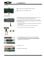
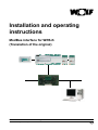
Installation and operating
instructions
ModBus interface for WRS-K
(Translation of the original)
Wolf GmbH · Postfach 1380 · D-84048 Mainburg · Tel. +49 8751/74-0 · Fax +49 8751/741600 · Internet: www.wolf-heiztechnik.de
Part no.: 3062947_201211 Subject to technical modifications.
GB
1. Index
Index
1. Index.....................................................................................2
2. Documentation information..................................................3
2.1 Other applicable documents..........................................3
2.2 Safekeeping of these documents...................................3
2.3 Symbols and warnings used..........................................3
2.4 Applicability of these instructions...................................3
3. Standards and directives......................................................4
3.1 Installation / commissioning...........................................4
3.2 Warnings........................................................................4
3.3 Service / repair...............................................................4
3.4 Disposal.........................................................................4
4. Installation.........................................................................5-6
4.1 View................................................................................5
4.2 Installation......................................................................5
4.3 Interface configuration....................................................6
5. Connection to a ModBus network........................................6
5.1 Connection.....................................................................6
6. Data.................................................................................7-14
6.1 Read access.............................................................7-10
6.1.1 Operating data read access...............................7-8
6.1.2 Special operating modes.......................................9
6.1.3 Alarms..............................................................9-10
6.2 Write access............................................................11-14
6.2.1 Operating data write access................................ 11
6.2.2 Operating mode selection...................................12
6.2.3 Manual mode / 7-day program............................13
6.2.4 BMS mode..........................................................14
7. Specification.......................................................................15
2
3062947_201211
2. Documentation information
2.1 Other applicable
documents
WRS-K installation and operating instructions.
2.2 Safekeeping of
these documents
The system operator or user should ensure the safekeeping of all instruction
manuals.
The instructions for all accessory modules and further accessories may also
apply.
→ Pass on these operating instructions as well as all other applicable
manuals.
2.3 Symbols and
warnings used
The following symbols are used in conjunction with these important
instructions concerning personal safety, as well as operational reliability.
"Safety instructions" are instructions with which you must comply exactly, to
prevent risks and injuries to individuals and material losses.
Danger through 'live' electrical components!
Please note: Switch OFF the ON/OFF switch before removing the casing.
Never touch electrical components or contacts when the ON/OFF switch is in
the ON position! This results in a risk of electrocution that may lead to injury
or death.
Please note
Warning structure
"Please note" indicates technical instructions that you must observe to
prevent material losses and equipment malfunctions.
You will recognise warnings in this manual by a pictogram with a line above
and below respectively. These warnings are structured according to the
following principle:
Signal word
Type and source of the risk.
Explanation of the risk.
→ Action to prevent the risk.
2.4 Applicability of
these instructions
3062947_201211
These operating instructions are valid for the ModBus interface for WRS-K.
3
3. Standards and directives
The components of the Wolf WRS-K control system comply with the
following regulations:
EC Directives
- 2006/95/EC Low Voltage Directive
- 2004/108/EC EMC Directive
EN Standards
- EN 55014-1 Emission
- EN 55014-2 Immunity
- EN 55022 Radio disturbance characteristics
- EN 55024 Immunity characteristics
- EN 60730-1 Automatic electrical controls for household and similar use
- EN 60730-2-9 Particular requirements for temperature sensing controls
- EN 61000-6-1 Immunity for residential, commercial and light-industrial
environments
- EN 61000-6-2 EMC Immunity for industrial environments
- EN 61000-6-3 EMC Emission standard for residential, commercial and
light-industrial environments
- EN 61000-6-4 Emission standard for industrial environments
- EN 61010-1 Safety requirements for electrical equipment for
measurement, control and laboratory use
3.1 Installation /
commissioning
- In accordance with DIN EN 50110-1, installation and commissioning may
only be performed by qualified electricians
- Observe all regulations stipulated by your local power supply utility and all
VDE or local regulations
- DIN VDE 0100 Regulations regarding the installation of high voltage
systems up to 1000 V
- DIN VDE 0105-100 Operation of electrical installations.
3.2 Warnings
Only operate the system in perfect technical condition. Immediately remove /
remedy any faults and damage that may impact on safety.
3.3 Service / repair
3.4 Disposal
Please note - Regularly check the perfect function of all electrical equipment.
- Only qualified personnel may remove faults or repair damage.
- Only replace faulty components or equipment with original Wolf spare
parts.
We accept no liability for any damage or loss resulting from technical
modifications to Wolf control units.
Observe the following information regarding the disposal of faulty system
components or the system at the end of its service life: Dispose of all
components in accordance with applicable regulations, i.e. separate material
groups correctly. The aim should be the maximum possible recycling of
basic materials with the least environmental impact. Never throw electrical or
electronic scrap into the household waste, but recycle it appropriately.
Generally, dispose of materials in the most environmentally responsible
manner according to environmental, recycling and disposal standards.
4
3062947_201211
4. Installation
4.1 View
2
1 Connection block to the KLM-M or KLM-L controller
2 Terminal block for the ModBus network
1
4.2 Installation
The ModBus interface is usually supplied fully assembled with the control
unit. If it is retrofitted, please observe the following points:
The ModBus interface is inserted into the "serial card" slot on the KLM-M
controller (part no. 2744747) or KLM-L controller (part no. 2744746). To do
this, proceed as follows:
1. Isolate the KLM-M or KLM-L air conditioning and ventilation module from
the power supply.
2. Remove the cover of the "serial card" slot using a screwdriver.
3. Remove the inner part of the cover with wire cutters.
4. Insert the ModBus interface into the free slot such that a plug-in
connection is made between the connection block of the ModBus
interface and the pins of the air conditioning and ventilation module
(connection block clicks into place).
5. Refit the slot cover.
6. Reconnect the power supply.
3062947_201211
5
4. Installation
5. Connection to a ModBus network
4.3. Interface
configuration
If the ModBus interface was supplied fully assembled with the
control unit, it is also already configured. No further settings are
required.
If the interface is retrofitted, it can be configured as follows:
Note
1. Navigate to the main menu with the Esc key on the BMK programming
module.
2. Select menu item Heating contractor with Enter.
3. Enter password "1234" and confirm with Enter.
4. Select menu item Other... with Enter.
5. Navigate to menu item BMS-Protocol with the up/down arrows.
6. Use Enter to highlight the BMS-Protocol and the up/down arrows to select
protocol type ModBus Slave Standard.
The transfer rate is then automatically set to 19200 and the BMS address
to 001.
7. Confirm these entries with Enter.
8. Use Esc to complete the entry and exit the menu item.
The precise procedure for operating the BMK programming
module can be found in the WRS-K installation and operating
instructions.
Note
S-04
Other...
BMS-Protocol
>MODBUS Slave Standard
Transfer rate
>19200 (SOLO RS485)
BMS-Address:
001
VALUE
5.1 Connection
SAVE
Esc CANCEL
Connection to the ModBus network is made via the pluggable terminal block:
1: 2: 3: GND
RX+/TX+
RX-/TX-
1 2 3
6
3062947_201211
6. Data
6. Data
Via the ModBus interface, it is possible to gain read and write access to the air
conditioning control unit.
6.1 Read access
With read access, actual and set values can be checked, subject to operating mode,
via a ModBus network.
Digital values can be scanned with function code 1 (read coils).
Analogue values can be scanned with function code 3 (read holding register).
6.1.1
Operating data
read access
The following data is available for read access:
3062947_201211
Description
Central fault
External system enable
Hygrostat humidity
Humidifier enable
System status
Operating status 1)
Pump, hot water
Pump, cold water
Heat source demand
Enable or pump HR
Outside/supply air damper
Exhaust/extract air damper
Enable gas valve
Enable or pump, adiabatic cooling
Enable convector heater (WO)
Thermostat, convector heater (WO)
Water supply line drain valve,
adiabatic cooling, open
Pan drain valve,
adiabatic cooling, open
Inlet valve,
adiabatic cooling, open
Supply air temperature
Outside temperature
Room temperature
Extract air temperature
Air quality (mixed gas)
Set room transducer
Room air humidity
Relative humidity, extract air
Relative humidity, supply air
Current set value, supply air
temperature
Current set temperature
Current set value, fresh air proportion
Current set speed, supply air fan
Current set speed, extract air fan
Current set value, relative humidity
Current set value, absolute humidity
Icing-up sensor
Actuating signal, heating
Actuating signal, cooling
Actuating signal, HR
Actuating signal, humidifier
Extract air temperature after
humidifier for adiabatic cooling
Actuation signal reheating 1)
Unit
-
Factor
-
Type
Digital
Digital
Digital
Digital
Digital
Digital
Digital
Digital
Digital
Digital
Digital
Digital
Digital
Digital
Digital
Digital
Digital
Index
1
2
3
4
5
117
60
18
61
62
63
64
65
87
89
90
91
-
-
Digital
92
-
-
Digital
94
°C
°C
°C
°C
V
°C
%r.h.
%r.h.
%r.h.
°C
0.1
0.1
0.1
0.1
0.1
0.1
0.1
0.1
0.1
0.1
Analog
Analog
Analog
Analog
Analog
Analog
Analog
Analog
Analog
Analog
1
2
3
4
5
6
7
8
9
10
°C
%
%
%
%r.h.
g/kg
°C
%
%
%
%
°C
0.1
1
0.1
0.1
0.1
0.1
0.1
0.1
0.1
0.1
0.1
0,1
Analog
Analog
Analog
Analog
Analog
Analog
Analog
Analog
Analog
Analog
Analog
Analog
11
12
13
14
23
24
27
28
29
30
31
32
%
0,1
Analog
33
7
6. Data
Description
Air quality (CO2)
Supply air pressure
Extract air pressure
Flow rate, supply air
Flow rate, extract air
Operating mode
Current set value, fan stage
Current set pressure, supply air
Current set pressure, extract air
Current set flow rate, supply air
Unit
ppm
Pa
Pa
m³/h
m³/h
Pa
Pa
m³/h
Factor
0.1
1
1
10
10
1
1
10
Type
Analog
Analog
Analog
Analog
Analog
Analog
Analog
Analog
Analog
Analog
Index
209
210
211
212
213
214
215
216
217
218
Current set flow rate, extract air
Cooling source demand, stage 1/2
Electric heater bank stage
Direct evaporator stage
Operating mode, heat pump 1)
m³/h
-
10
-
Analog
219
220
232
233
255
Analog
Analog
Analog
Analog
1) Available WRS-K software version 3.0.000 or higher
Values with a factor = 0.1 have a decimal place. Multiply the transferred value by the
factor 0.1.
Example: Transferred value for supply air temperature = 243 -> actual value = 24.3 °C.
For values with a factor = 1, the transferred value equals the actual value
(no decimal place).
Example: Transferred value for fresh air proportion = 45 -> actual value = 45%.
For values with a factor = 10, the transferred value needs to be multiplied by 10.
Example: Transferred value for supply air flow rate = 125 -> actual value = 1250 m³/h
Note: Subject to the implementation of the MODBUS connection, it may be
necessary to add the value of 1 to the index.
Codierung
Description
Value
Explanation
Current set value, fan stage
0
Fans Off
1
Fans On (single stage and variable fans)
Fans stage 1 On (multi stage fans)
2
Fans stage 2 On
3
Fans stage 3 On
0
Manual mode
1
7-day program
2
BMS mode
0
Standby
1
Ready for operation
0
System not in use
1
System in use
0
Not enabled
1
Enable heating
2
Enable cooling
Operating mode
System status
Operating status
Operating mode, heat pump
8
3062947_201211
6. Data
6.1.2
Special operating
modes
Any special operating modes which are enabled will be transferred as described
below. Function descriptions of the special operating modes can be found in the
WRS-K installation and operating instructions.
Description
Holiday program
Filter test
Preheat program
Night ventilation
Backup mode
Extension of utilisation time
Peak ventilation
Natural cooling
Hygrostat function
Air quality control
External demand
Run-on
HR-Ice guard
HR-Ice guard
Speed reduction
Setback mode 1)
Winter start HR 1)
Type
Digital
Digital
Digital
Digital
Digital
Digital
Digital
Digital
Digital
Digital
Digital
Digital
Digital
Digital
Digital
Digital
Digital
Index
6
7
8
9
10
11
12
13
14
15
16
17
92
101
102
112
113
1) Available WRS-K software version 3.0.000 or higher
Explanation
Value
0
1
Explanation
Special operating mode not enabled
Special operating mode enabled
Note: Several special operating modes can be enabled at the same time.
6.1.3 Alarms
Any enabled alarms will be transferred as described below. Descriptions of the
causes and possible solutions can be found in the WRS-K installation and operating
instructions.
Description
Fault, inverter, supply air fan
Motor temperature too high, supply air fan
Repair switch, supply air fan
Air flow monitor, supply air
Fault, inverter, extract air fan
Motor temperature too high, extract air fan
Repair switch, extract air fan
Air flow monitor, extract air
Outside air filter contaminated
Supply air filter contaminated
Extract air filter contaminated
Pump fault, DHW bank
Frost stat has responded
Frost protection temperature, supply air not reached
Temperature limiter, electric heater bank
High limit safety cut-out, electric heater bank
Fault, pump, cold water bank
Central fault, external refrigeration unit
Alarm, fire alarm system
Supply air temperature sensor faulty or not connected
Supply air humidity sensor faulty or not connected
Room temperature sensor faulty or not connected
3062947_201211
Type
Digital
Digital
Digital
Digital
Digital
Digital
Digital
Digital
Digital
Digital
Digital
Digital
Digital
Digital
Digital
Digital
Digital
Digital
Digital
Digital
Digital
Digital
Index
19
20
21
22
23
24
25
26
27
28
29
30
31
32
33
34
35
36
37
38
39
40
9
6. Data
Description
Room air humidity sensor faulty or not connected
Extract air temperature sensor faulty or not connected
Extract air humidity sensor faulty or not connected
Outside temperature sensor faulty or not connected
Outside humidity sensor faulty or not connected
Icing-up sensor HR faulty or not connected
Fire damper responded
Fault, EC motor, supply air fan
Fault, EC motor, extract air fan
Databus fault, extension modules
Remote control not connected or databus fault
Service required
Icing-up temperature HR below set value 2)
Fault, heat recovery
Service message, humidifier
Fault, humidifier
External fault
Smoke detector responded
Set value transducer not or incorrectly connected
Fire damper 1 responded
Fire damper 2 responded
Fire damper 3 responded
Fire damper 4 responded
Fire damper 5 responded
Fire damper 6 responded
Fire damper 7 responded
Fire damper 8 responded
Fire damper 9 responded
Fire damper 10 responded
Fire damper 11 responded
Fire damper 12 responded
Fire damper 13 responded
Fire damper 14 responded
Fire damper 15 responded
Fire damper 16 responded
Fire damper 17 responded
Fire damper 18 responded
Fire damper 19 responded
Fire damper 20 responded
Fire damper 21 responded
Scaling, freshwater contact humidifier, adiabatic cooling
Fault, convector heater (WO) burner
Fault, humidifier for adiabatic cooling
No adiabatic cooling
Humidifier for adiabatic cooling at risk of icing up
Extract air temperature sensor downstream of humidifier for
adiabatic cooling faulty or not connected
Service message, humidifier for adiabatic cooling
Fault, heat pump 1)
Pump fault, reheater bank1)
Frost thermostat responded, reheater bank 1)
Type
Digital
Digital
Digital
Digital
Digital
Digital
Digital
Digital
Digital
Digital
Digital
Digital
Digital
Digital
Digital
Digital
Digital
Digital
Digital
Digital
Digital
Digital
Digital
Digital
Digital
Digital
Digital
Digital
Digital
Digital
Digital
Digital
Digital
Digital
Digital
Digital
Digital
Digital
Digital
Digital
Digital
Digital
Digital
Digital
Digital
Digital
Index
41
42
43
44
45
46
47
48
49
50
51
52
53
54
55
56
57
58
59
66
67
68
69
70
71
72
73
74
75
76
77
78
79
80
81
82
83
84
85
86
88
95
96
97
98
99
Digital
Digital
Digital
Digital
100
114
115
116
1) Available WRS-K software version 3.0.000 or higher
2) Available up to WRS-K software version 2.1.031
10
3062947_201211
6. Data
Explanation
Value
0
1
Explanation
Alarm disabled
Alarm enabled
Note: Several alarms can be enabled at the same time.
An alarm remains enabled until it is acknowledged at the BMK
programming module.
6.2
Write access
With write access, set values can be specified or adjusted, subject to operating mode,
via a ModBus network. In addition, the system can be switched on or off and the
operating mode specified.
These values can be written with function code 6 (write single register) or
function code 16 (write multiple register).
6.2.1
Operating data
write access
The following data is available for write access:
Description
Set temperature from BMS
Set speed, supply air fan from BMS
Set speed, extract air fan from BMS
Set value, fresh air proportion from BMS
Set pressure, supply air from BMS
Set pressure, extract air from BMS
Set flow rate, supply air from BMS
Set flow rate, extract air from BMS
Set value, fan mode (stage or ON/
OFF) from BMS
Set value, relative humidity from BMS
Set value, absolute humidity
from BMS
Offset set temperature
Offset set speed, supply air fan
Offset set speed, extract air fan
Offset set value, fresh air proportion
Offset set pressure, supply air
Offset set pressure, extract air
Offset set value, relative humidity
Offset set value, absolute humidity
Offset set flow rate, supply air
Offset set flow rate, extract air
Operating mode
Unit
°C
%
%
%
Pa
Pa
m³/h
m³/h
-
Factor
0.1
0.1
0.1
1
1
1
10
10
-
Type
Analog
Analog
Analog
Analog
Analog
Analog
Analog
Analog
Analog
Index
15
16
17
221
223
224
225
226
222
%r.h.
g/kg
0.1
0.1
Analog
Analog
25
26
K
%
%
%
Pa
Pa
%r.h.
g/kg
m³/h
m³/h
-
0.1
0.1
0.1
1
1
1
0.1
0.1
10
10
-
Analog
Analog
Analog
Analog
Analog
Analog
Analog
Analog
Analog
Analog
Analog
18
19
20
227
228
229
21
22
230
231
214
Values with a factor = 0.1 are transferred with a decimal place. The required value
equals the specified value times 0.1.
Example: Required value for set temperature = 24.3 °C -> value to be specified = 243.
For values with a factor = 1, the value to be specified equals the required value
(no decimal place).
Example: Required value for set fresh air proportion = 45% -> value to be specified = 45.
For values with a factor = 10, the required value equals the value to be specified multiplied
by 10.
Example:
Required value for set flow rate, supply air = 1300 m³/h -> value to be specified = 130.
Note:
3062947_201211
Subject to the implementation of the MODBUS connection, it may be
necessary to add the value of 1 to the index..
11
6. Data
6.2.2 Operating mode
selection
If a ModBus interface is installed, the system can be operated in 3 different
operating modes:
-
-
-
Manual mode
7-day program
BMS mode
Manual mode
The system runs with the set values specified for manual mode via the BMK
programming module. The set values can be adjusted via offsets using the
ModBus interface.
7-day program
The system runs with the times and set values specified in the 7-day
program. The set values can be adjusted via offsets using the ModBus
interface.
BMS mode
The system runs with the set values specified via the ModBus interface. The
system is switched on and off via the ModBus interface.
The operating mode can be changed via the BMK programming module or
the ModBus interface.
- Selecting the operating mode via the BMK programming module:
1. Navigate to the main menu with the Esc key on the BMK programming
module.
2. Select menu item Standard settings with Enter.
3. Navigate to the operating mode with the up/down arrows.
4. Highlight the operating mode with Enter.
5. Select the required operating mode with the up/down arrows and confirm
with Enter.
Standard setting
GE-18
7-day program
active
+ BMS offset
Esc BACK
SELECTION
DISPLAY
6. Use Esc to complete the entry and exit the menu item.
- Selecting the operating mode via ModBus interface:
The system operating mode can be specified via ModBus:
Value
0
1
2
12
Explanation
Manual mode
7-day program
BMS mode
3062947_201211
6. Data
6.2.3
Manual mode /
7-day program
In manual mode or with a 7-day program enabled, the set values can be
adjusted via the offset variables. The system runs as specified by manual
mode or the 7-day program.
The following variables are effective:
- Offset set temperature (adjusting the set temperature)
- Offset set speed, supply air fan (adjusting the set speed for the supply air fan)
- Offset set speed, extract air fan (adjusting the set speed for the extract air fan)
- Offset set value, fresh air proportion (adjusting the fresh air proportion)
- Offset set pressure, supply air (adjusting the set pressure for the supply air fan)
- Offset set pressure, extract air (adjusting the set pressure for the extract air fan)
-Offset set flow rate, supply air
(adjusting the set flow rate for the supply air)
-Offset set flow rate, extract air
(adjusting the set flow rate for the extract air)
- Offset set value, relative humidity (adjusting the set value for relative humidity)
- Offset set value, absolute humidity (adjusting the set value for absolute humidity)
- Operating mode
Please note
Any adjustment of the set values is always relative to the set values
selected for manual mode or the 7-day program.
Systems with BMK-F remote control:
Adjusting the set temperature:
If the set value is adjusted via the ModBus interface, after the set value has
been altered via the remote control, a changeover is made to the set value
for manual mode or the 7-day program, plus offset, via the ModBus interface.
Example:
Set value for manual mode = 21 °C; set value adjusted via BMK-F to 23 °C.
If an offset = -1 K is then specified, a new set value of 20 °C (21 °C – 1 K) is
enabled.
Adjustment of set speed / pressure / flow rate:
The set values for speed or pressure can be adjusted via the remote control
in 3 stages (see WRS-K installation and operating instructions). Here, the set
value is altered according to the values specified in the standard settings for
supply air and extract air.
If, after altering a set value via the remote control, a set value is adjusted
via the ModBus interface for supply air or extract air, a changeover is made
to the set values for manual mode or the 7-day program, plus offset, via the
ModBus interface for supply air and extract air.
Example:
Set speed for supply air in manual mode = 50%; set speed for extract air in
manual mode = 45%; set speeds changed via BMK-F to 60% (supply air)
and 55% (extract air).
If an offset for the supply air speed of 30% is then specified, but no offset for
the extract air fan is set, new set values of 80% (50%+30%) for the supply
air fan and 45% (= set value for manual mode) for the extract air fan are
enabled.
Adjusting the set value for fresh air proportion:
If the set value is adjusted via the ModBus interface, after the set value has
been altered via the remote control, a changeover is made to the set value
for manual mode or the 7-day program, plus offset, via the ModBus interface.
Example:
Set value for manual mode = 40%; set value adjusted via BMK-F to 50%.
If an offset = -10% is then specified, a new set value of 30% (40%-10%) is
enabled.
3062947_201211
13
6. Data
6.2.4 BMS mode
In BMS mode, all set values are specified via the ModBus interface. The
system is also switched on and off via the ModBus interface.
The following variables are effective:
-
-
-
-
-
-
-
-
-
-
-
-
Set temperature from BMS
Set speed, supply air fan from BMS
Set speed, extract air fan from BMS
Set value, fresh air proportion from BMS
Set pressure, supply air from BMS
Set pressure, extract air from BMS
Set flow rate, supply air from BMS
Set flow rate, extract air from BMS
Set value, fan mode from BMS
Set value, relative humidity from BMS
Set value, absolute humidity from BMS
Operating mode
Via set value, fan mode from BMS, the fans are switched on and the system
is enabled with the set values specified via the ModBus interface:
For single stage and variable speed fans:
Value
Explanation
0
1
System OFF
System ON
For multi stage fans (2- or 3-stage):
Value
0
1
2
3
Explanation
System OFF
System ON with fan stage 1
System ON with fan stage 2
System ON with fan stage 3
Systems with BMK-F remote control:
Set temperature:
If the set value has been altered via the remote control, a new set value
specification is accepted via the ModBus interface when the value of set
temperature from BMS is changed.
Set speed / pressure:
If the set value has been altered via the remote control, a new set value
specification is accepted via the ModBus interface when the value of set
speed, supply air fan from BMS or set speed, extract air fan from BMS (or
set pressure, supply air from BMS, or set pressure, extract air from BMS)
is changed. As soon as a new set value for supply air or extract air is
specified, the set values specified via the ModBus interface for supply air
and extract air are enabled.
If the set value for the supply air speed or supply air pressure is set to 0, the
set value for the extract air speed is also set to 0.
Set value for fresh air proportion:
If the set value has been altered via the remote control, a new set value
specification is accepted via the ModBus interface when the value of the set
value, fresh air proportion from BMS is changed.
14
3062947_201211
7. Specification
7. Specification
Operating conditions
Storage conditions
Protocol
Maximum baud rate
Power supply
Cable
Maximum cable length
3062947_201211
-10-60 °C, 20-80% r.H. not condensing
-20-70 °C, 20-80% r.H. not condensing
ModBus Slave RTU, 8 databits, 2 stopbits, no parity
19200
Via KLM controller
AWG 20/22 screened
1000m
15
Wolf GmbH · Postfach 1380 · D-84048 Mainburg · Tel. +49 8751/74-0 · Fax +49 8751/741600 · Internet: www.wolf-heiztechnik.de