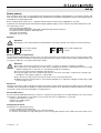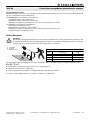
1
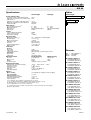
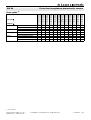
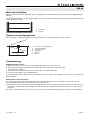
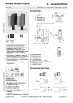
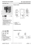
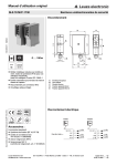
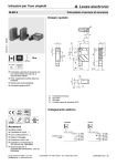
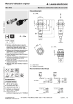
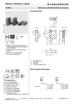
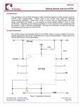
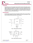
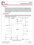
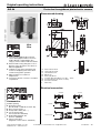
Original operating instructions SLS 96 Protective throughbeam photoelectric sensors en 09-2010/11 602075 Dimensioned drawing 65m 39m 10 - 30 V DC 500 Hz We reserve the right to make changes • DS_SLS_96_en.fm Protective throughbeam photoelectric sensor with high performance reserve in visible red light or infrared light, up to category 2 in accordance with ISO 13849-1 Robust metal housing with glass cover or plastic housing, protection class IP 67 for industrial application 2 indicators each at the transmitter and receiver for displaying their status when commissioning and in operation Optics heating for use with low temperatures Connection via M12 connector or terminal compartment A B C D E F G H I Green indicator diode Yellow indicator diode Transmitter/receiver Optical axis Device plug M12x1 Screwed cable gland M16x1.5 for Ø 5 … 10mm Countersinking for SK nut M5, 4.2 deep Connection terminals Cable entry Electrical connection IP 67 Transmitter C IEC 60947... IEC 60947... UL Receiver US LISTED Accessories: (available separately) Mounting systems (BT 96, BT 96.1, UMS 96, BT 450.1-96) M12 connectors (KD …) Ready-made cables (K-D …) Test monitoring units TNT 35 (Part No. 50033058) BT 96-ARH alignment aid (Part No. 50080502) Sensorscope SAT 5 (alignment control, Part No. 50109545) Leuze electronic GmbH + Co. KG [email protected] • www.leuze.com Terminals Connector, 4-pin In der Braike 1 D-73277 Owen Tel. +49 (0) 7021 573-0 SLS 96 M/P… - 08 SLS 96 Specifications Tables Infrared light Red light Safety-relevant data Type in accordance with IEC/EN 61496 Performance Level (PL) in accordance with ISO 13849-1 1) Category in accordance with ISO 13849 1) Mean time to dangerous failure (MTTFd) Service life (TM) Infrared light 0 type 2 PL d 50 65 Red light 0 cat. 2 400 years 20 years 30 39 Operating range [m] Typ. operating range limit [m] Optical data Typ. operating range limit 2) Operating range 3) Light source Wavelength 0 … 65m 0 … 50m LED (modulated light) 880nm 0 … 39m 0 … 30m LED (modulated light) 660nm Timing Sensor switching frequency Sensor response time Delay before start-up 500Hz 1ms ≤ 200ms Electrical data Operating voltage UB 4) Residual ripple 10 … 30VDC (incl. residual ripple) ≤ 15% of UB Open-circuit current Switching output Function Signal voltage high/low Output current ≤ 50mA PNP transistor light switching ≥ (UB -2V)/≤ 2V max. 100mA Indicators Receiver Green LED Yellow LED Yellow LED, flashing Transmitter Green LED Yellow LED Mechanical data Housing Optics cover Weight Connection type ready light path free light path free, no performance reserve Remarks ready transmitter active SLS = SLSS = SLSE = Plastic housing Metal housing polycarbonate diecast zinc plastic glass 150g 380g terminals or M12 connector -20°C … +60°C/-40°C … +70°C 1, 2, 3 II, all-insulated IP 67 1 (acc. to EN 60825-1) IEC 60947-5-2 1) 2) 3) 4) 5) 6) SLSS 96K-1080-T2-24 SLSE 96K/P-1070-T2-21 SLSS 96K-1080-T2-45 SLSE 96K/P-1070-T2-41 SLS 96K/P-1200-T2-2 SLSS 96K-1210-T2-24 SLSE 96K/P-1200-T2-21 SLS 96K/P-1200-T2-4 Options Optics heating Low temperature Activation input active Transmitter active/not active Activation/disable delay Input resistance SLS 96K/P-1070-T2-2 SLS 96K/P-1070-T2-4 Environmental data Ambient temp. (operation/storage) Protective circuit 5) VDE safety class 6) Protection class LED class Standards applied Pair consisting of Transmitter Receiver for temperature changes, prevents fogging to -35°C ≥ 8V/≤ 2V ≤ 1ms 10KΩ ± 10% In combination with a suitable test monitoring unit, e.g. TNT 35 Typ. operating range limit: max. attainable range without performance reserve Operating range: recommended range with performance reserve For UL applications: for use in class 2 circuits only 1=transient protection, 2=polarity reversal protection, 3=short circuit protection for all outputs Rating voltage 250VAC SLSS 96K-1210-T2-45 SLSE 96K/P-1200-T2-41 SLS 96K/P-1207-T2-2 SLSS 96K-1210-T2-24 SLSE 96K/P-1207-T2-21 SLS 96K/P-1207-T2-4 SLSS 96K-1210-T2-45 SLSE 96K/P-1207-T2-41 SLS 96M/P-1070-T2-2 SLSS 96M-1080-T2-24 SLSE 96M/P-1070-T2-21 SLS 96M/P-1070-T2-4 SLSS 96M-1080-T2-45 SLSE 96M/P-1070-T2-41 SLS 96M/P-1071-T2-2 SLSS 96M-1090-T2-24 SLSE 96M/P-1071-T2-21 SLS 96M/P-1071-T2-4 SLSS 96M-1090-T2-45 SLSE 96M/P-1071-T2-41 SLS 96M/P-1200-T2-2 SLSS 96M-1210-T2-24 SLSE 96M/P-1200-T2-21 SLS 96M/P-1200-T2-4 SLSS 96M-1210-T2-45 SLSE 96M/P-1200-T2-41 SLS 96 M/P… - 08 2010/11 Equipment Housing Light source Connection Features Leuze electronic GmbH + Co. KG [email protected] • www.leuze.com SLS 96K/P-1200-T2-4 Part No. 50028011 (Tr) Part No. 50028012 (Re) SLS 96K/P-1207-T2-2 Part No. 50028009 (Tr) Part No. 50035078 (Re) SLS 96K/P-1207-T2-4 Part No. 50028011 (Tr) Part No. 50041109 (Re) metal plastic red light (30m) infrared light (50m) terminals M12 connector optics heating/low temperature activation input filter for multi-axis operation SLS 96K/P-1200-T2-2 Part No. 50028009 (Tr) Part No. 50028010 (Re) Order code SLS 96K/P-1070-T2-4 Part No. 50031559 (Tr) Part No. 50031561 (Re) Selection table SLS 96K/P-1070-T2-2 Part No. 50081292 (Tr) Part No. 50081293 (Re) In der Braike 1 D-73277 Owen Tel. +49 (0) 7021 573-0 SLS 96M/P-1200-T2-4 Part No. 50031249 (Tr) Part No. 50031250 (Re) SLS 96M/P-1200-T2-2 Part No. 50025209 (Tr) Part No. 50031562 (Re) SLS 96M/P-1071-T2-2 Part No. 50029454 (Tr) Part No. 50029455 (Re) SLS 96M/P-1071-T2-4 Part No. 50080478 (Tr) Part No. 50080479 (Re) SLS 96M/P-1070-T2-4 Part No. 50025215 (Tr) Part No. 50025193 (Re) SLS 96M/P-1070-T2-2 Part No. 50025213 (Tr) Part No. 50025192 (Re) SLS 96 Protective throughbeam photoelectric sensors Order guide 1) 1) Version 2010 A-Z SLS 96 M/P… - 08 SLS 96 Safety notices Before using the safety sensor, a risk evaluation must be performed according to valid standards. For mounting, operation and tests, this document as well as all applicable national and international standards and regulations must be observed, printed out and handed to the affected personnel. Before working with the safety sensor, completely read and observe the documents applicable to your task. In particular, the following national and international legal regulations apply for the commissioning, technical inspections and work with safety sensors: - Machinery directive 2006/42/EC - Use of Work Equipment Directive 89/655/EEC supplemented by Directive 95/63 EC - Accident-prevention regulations and safety rules - Other relevant standards - Standards, e.g. ISO 13855 Symbols Attention! Warning sign – This symbol indicates possible dangers. Please pay especially close attention to these instructions! These symbols identify the transmitter. These symbols identify the receiver. Safety sensor area of application The protective throughbeam photoelectric sensor is an active optoelectronic protective device only in connection with a safetyrelevant control system, in which the cyclical testing of transmitter and receiver is carried out in accordance with EN 61496-1, up to category 2 and PL d in accordance with EN ISO 13849-1. Attention! The safety sensor protects persons at access points or at points of operation of machines and plants. The safety sensor only detects persons upon entry to the danger area; it does not detect persons who are located within the danger area. For this reason, a start-up/restart interlock is mandatory. No protective function without adequate safety distance. The power supply unit used to operate the photoelectric sensor has to be able to compensate for changes and interruptions of the supply voltage acc. to EN 61496-1. Also observe the safety notices in the documentation of the connected test device! Additional measures must be taken to ensure that the AOPD does not experience a dangerous failure due to glare from other light sources. Proper use The safety sensor must only be used after it has been selected in accordance with the respectively valid instructions and relevant standards, rules and regulations regarding occupational safety and safety at work, and after it has been installed on the machine, connected, commissioned, and checked by a competent person. Foreseeable misuse Any use other than that defined under the "Proper use" or which goes beyond that use is considered improper use. The user must ensure that no optical influence on the AOPD occurs through other forms of light beams, e.g. through - wireless control devices on cranes, - radiation from welding sparks, - stroboscopic lights. Competent personnel Prerequisites for competent personnel: - He has a suitable technical education. - He knows the instructions for the safety sensor and the machine. - He has been instructed by the responsible person on the mounting and operation of the machine and of the safety sensor. SLS 96 M/P… - 08 2010/11 SLS 96 Protective throughbeam photoelectric sensors Responsibility for safety Manufacturer and operator must ensure that the machine and implemented safety sensor function properly and that all affected persons are adequately informed and trained. The manufacturer of the machine is responsible for: - Safe implementation of the safety sensor. - Imparting all relevant information to the operator. - Adhering to all regulations and directives for the safe commissioning of the machine. The operator of the machine is responsible for: - Instructing the operating personnel. - Maintaining the safe operation of the machine. - Adhering to all regulations and directives for occupational safety and safety at work. - Regular testing by competent personnel. Safety distances Attention! The protective throughbeam photoelectric sensor must be installed with the correctly calculated safety distance as well as suitable beam distances from a potentially dangerous motion: if an interruption of the light beam occurs, the danger area may only be reached once the machine has already come to a dead stop. a b c Transmitter Receiver Deflection mirror b 400 mm 900 mm a c Beam distances in accordance with ISO 13855 Number of Heights above reference plane, Additional distance C beams e.g. floor [mm] [mm] 1 750 1200 2 400, 900 850 3 300, 700, 1100 850 4 300, 600, 900, 1200 850 The safety distance S between photoelectric sensor and danger area is calculated using the following formula (ISO 13855): S = (K · T) + C S: Safety distance [mm] between photoelectric sensor and danger area. K: Approach speed (constant = 1600 mm/s). T: Time delay [s] between interruption of the light beam and stand-still of the machine. C: Safety constant (additional distance) = 850mm or 1200mm, see table above. Leuze electronic GmbH + Co. KG [email protected] • www.leuze.com In der Braike 1 D-73277 Owen Tel. +49 (0) 7021 573-0 SLS 96 M/P… - 08 SLS 96 Multi-axle installation With multi-axle installation the light beams have to run parallel to the reference plane (e.g. floor) and must be aligned mutually parallel. For this the beam direction must be set oppositely in each case. Otherwise the light beams could cause mutual interference and disturb proper functioning. b a a b a b Transmitter Receiver Distance to reflecting surfaces When mounting, a sufficiently large distance from the optical axis to reflecting surfaces must be selected. d 4˚ c f e 4˚ a b c d e f Distance to the reflecting surface Protected field width Reflecting surface Transmitter Receiver Object Commissioning Alignment of the sensors Mount photoelectric sensors with corresponding fixing brackets from Leuze electronic. Apply operating voltage to transmitter and receiver and activate transmitter via activation input (see "Electrical connection"). Green LEDs on transmitter and receiver and yellow LED on transmitter illuminate. Position receiver until the yellow LED illuminates. Receiver LED blinks yellow: Light path free, but no performance reserve; clean and readjust photoelectric sensor, or check operating conditions. Safety notices for test function 1. To perform testing correctly the activation input of the SLS 96 transmitter must be connected to a test monitoring unit. 2. The test duration during access protection must not exceed 150ms. 3. Subsequent to sensor activation the output switching elements of the test monitoring unit must remain in the 'off' state for at least 80ms so that the downstream equipment can be switched off safely when the photoelectric sensor is used for access protection. 4. In order to comply with points 2 and 3, the use of Leuze electronic test monitoring units (TNT 35, MSI-m) is recommended. SLS 96 M/P… - 08 2010/11 SLS 96 Protective throughbeam photoelectric sensors Check The checks should ensure that the Optoelectronic Protective Devices have been used acc. to the national/international regulations, in particular in accordance with the machine and work-equipment directive. Check before initial commissioning Observe the nationally and internationally valid regulations. Is the required safety distance (protective field of the safety sensor to the next point of operation) maintained? Is the safety sensor effective during the entire dangerous movement and in all adjustable operating modes of the machine? It must not be possible to climb over, climb under or circumvent the light path. Ensure that the sensor only detects persons upon entry to the danger area and does not detect whether persons are located within the danger area. Is a start-up/restart interlock present? Before they begin work, have a competent person train the operating personnel in their respective tasks. Regular testing by competent personnel The reliable interaction of safety sensor and machine must be periodically tested in order to detect changes to the machine or impermissible tampering with the safety sensor. Have all tests performed by competent personnel. Observe the nationally and internationally applicable regulations and the time periods specified therein. Daily check of the effectiveness of the safety sensor It is extremely important to examine the effectiveness of the protective field daily so that it is ensured that e.g even with adjustments to e.g. parameters, the protective function is active at all points. Interrupt the light beam between the transmitter and receiver (test rod Ø 30mm) - in front of the transmitter. - in the middle between the transmitter and receiver. - in front of and behind the deflection mirror. It must not be possible to initiate the dangerous state during beam interruption. Disposal For disposal observe the applicable national regulations regarding electronic components. Leuze electronic GmbH + Co. KG [email protected] • www.leuze.com In der Braike 1 D-73277 Owen Tel. +49 (0) 7021 573-0 SLS 96 M/P… - 08 SLS 96 SLS 96 M/P… - 08 2010/11