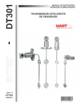
1
BA 1731/1733
Operating instructions
EN – Rev. 2
Page 1 / 7
Swing check valves
Table of contents
An incorrect use of the valves may cause strong consequences
to the complete plant, such as:
1.
2.
3.
4.
5.
6.
7.
8.
-
escape of medium
-
standstill of a plant/machine
-
affects, decreases or increases of operation or work of a
plant / machine
Generalities
Safety
Corrosion protection, transport and storage
Description / corresponding documents
Installation
Operation / putting into and out of operation
Maintenance / Commissioning
Malfunctions and their elimination
1. Generalities
The following operating instructions are valid for KLAUS UNION
swing check valves of the series 1731 and 1733, which are installed in pipelines and serve to let through the flow of liquids
(gases and steams) in only one direction.
KLAUS UNION valves are subjected to the rules according to
the PED 97/23/EC and their harmonised standards / regulations, in their development, construction and testing.
By a correct assembling, maintenance or repair we guarantee a
trouble-free valve operation.
The manufacturer carries no responsibility for efficiency and
safety of the valves, whenever these operating instructions are
not observed and followed accurately.
The valves are marked, in accordance with DIN/EN 19 (ISO
5209) as follows: nominal diameter (DN), nominal pressure
(PN), body material, heat-no or specimen-no, manufacturer
brand, factory number, flow direction arrow, and if necessary,
admissible working temperature and admissible operating pressure (bar). By attaching a CE marking to the valves, we concurrently declare compliance with PED 97/23/EC.
ATTENTION The valves must not be activated beyond the limits and rules indicated in the different documents (such as operating instructions, purchase documents, type sheets). Operations beyond the indicated limits lead to overstrain which cannot
be sustained by the valves.
For any further inquiries or in case of damage, please contact
KLAUS UNION GmbH & Co. KG, Bochum.
In case of local inquiries or orders, especially for spare parts,
please indicate the production or factory serial number, the
type, the model version and possibly also the year of construction.
The technical data (service data) referring to the valves can be
found in their technical documentation (paragraph 4).
In case of a return transport it has to be proceeded as explained in paragraph 3 <Transport>.
2. Safety
These operating instructions contain essential information that
has to be observed by assembling, operation and maintenance
of the valves. For this reason they have to be read by the assembling staff, by the skilled staff and by the operator before
the valves are assembled and put into operation and they
should always be kept in the proximity of the valves.
Not only the general safety instructions indicated in this main
paragraph have to be observed, but also the other ones indicated in other paragraphs.
2.1 Indication of notes in the operating instructions
The safety instructions contained in these operating instructions, which have to be observed in order to avoid injuries to
persons, are indicated by the following general and particular
picot-graphs:
A non-observance of this warning can cause injuries
to persons and defects of the machines, such as:
-
Injuries caused by escaped medium (cold/hot, toxic, under
pressure)
-
Affect in activity or damage of the valves
The descriptions and rules included in these operating instructions refer to standard types but are also valid for alternatives.
These operating instructions do not take into consideration:
Security signal acc. to DIN 4844 W 9
Beware of the electrical voltage!
Any accident and incident which can arise by assembling, operation or maintenance of the valves.
Any safety rule in relation with the place where the valve is installed. The operating company is responsible for the observation of the safety rules, - also by the assembling staff.
ATTENTION It is essential that the valves are handled by
skilled staff that must be aware of the interactions between the
valves and the plants in which they are installed.
Security signal acc. to DIN 4844 - W 8
.
In order to avoid defects of valve efficiency and of its accessories the following warning mark has to be observed in safety
instructions:
ATTENTION
The signs marked directly on the valves (such as nominal pressure) have absolutely to be considered and kept in a readable
condition.
BA 1731-1733 Swing check valves_Rev.2_EN.doc
Issue 01/2010
KLAUS UNION GmbH & Co. KG
Page 2 / 7
2.2 Dangers that can result if safety instructions are not observed.
alities> of these operating instructions. The limits included in the
technical documentation must not be exceeded.
The non-observance of the safety instructions may cause risks
to persons, the environment and the valves or plants. The nonobservance of the safety instructions may lead to the loss of
any indemnity rights.
3. Corrosion protection, transport and
storage
In particular the non-observance of the safety notes can cause
dangers such as:
-
break down of important functions of the valves / plants
-
failure of prescribed methods of maintenance and commissioning
-
danger to persons caused by electrical, mechanical and
chemical impacts
-
environmental injuries caused by a leakage of dangerous
materials
2.3 Working with safety consciousness
The safety instructions included in these operating instructions,
the national regulations for prevention of accidents, as well as
the internal regulations referring to work, operation and safety
have to be observed by the operator.
2.4 Safety instructions for the operator / user
-
Whenever some hot or cold valve parts (e.g. casing parts,
lever or handwheel) may cause any danger, the operator
must construct these parts in a way that they are protected
from contacts.
-
The contact protection for moving parts (such as lever or
weight) must not be taken away while the machine is working.
-
Leakages (f. ex. in shaft sealing) of dangerous conveyed
materials (explosive, toxic, hot) have to be removed in a
way that no danger to persons or environment can arise.
Legal determinations must be respected.
-
Injuries by electrical energy have to be excluded (please
find details to this point in the VDE and local power supply
enterprise regulations).
2.5 Safety instructions for maintenance, inspection and assembly works.
3.1 Corrosion protection
3.1.1
Carbon steel valves
Valves made out of unalloyed or low alloyed cast steel are
painted with a hard sticking primer made of a 2-components
colour based on epoxy resin paint. The minimum film thickness
is 70 µm. The inner surfaces are free of paint and only coated
with a temporary corrosion protection (e.g. oil). Machined flange
facings are protected against outside influences with a strippable varnish.
3.1.2
Austenitic valves
Valves made out of stainless austenitic cast steel will be delivered without coating.
3.2 Transport
The valves are delivered with their connecting holes shut by
cover caps. See that valves are not thrown or exposed to hard
crushes.
Valves will be supplied as ready for operation.
ATTENTION During transport and intermediate storage valves
have to be closed. Connecting holes have to be shut up by
suitable means (cover caps, foils) in order to avoid any damage
to the valve seats.
Please see on this the “rise prescriptions“on page 7!
Valve weights are indicated in the corresponding manufacturer
documents (type sheets, paragraph 4.1 <Corresponding documents>, acknowledgement)
After delivery, respectively before assembly the valves have to
be inspected in order to exclude any transportation damage.
3.3 Storage
It must be provided that all maintenance, inspection and assembly works are executed by skilled staff, who must have previously studied these operating instructions.
The storage / intermediate storage of the valves has to be effected in a way that it can work perfectly even after a longer
storage period. For this purpose it is necessary:
Basically when any kind of work on valves is executed, they
have to be cooled down and free of pressure. And the vaporisation temperature of the medium must be lower than the temperature of all parts it gets in contact with.
-
to keep the valve closed (in order to protect the seat facings)
-
to take measures against soiling (dust, sand, mortar, respectively building materials), frost and corrosion (e.g. using plastic foils)
Valves which get in contact with health injuring media have to
be decontaminated.
Immediately after the work is done, all safety and protection
devices have to be put into position or operation again. Before
putting the valve into operation again, the points referring to
paragraph 6 <Putting into operation> have to be observed.
2.6 Independent conversion and spare parts
manufacture
Reconstructions or modifications of the valves are only acceptable under agreement with the manufacturer. The use of original spare parts and by the manufacturer authorised accessories
promotes safety. Any violations cause the liability for the consequences arising to be cancelled.
When storing valves with soft gaskets (seat and / or stem seal
of elastomer) the storage regulations for elastomer (DIN 7716)
have to be observed:
-
the store must be dry, free of dust and moderately ventilated. Store temperature should not go over +25 °C
-
stocks on hand have to be used up in order to avoid long
storage periods
-
as already mentioned above, the valves have to be in
”closed“position during the storage. However the soft closure elements should be shut with little power, in order to
avoid a rush ageing of the elastomer
2.7 Inadmissible operation modes
A safe operation is only guaranteed if the valves are used according to the determinations included in paragraph 1 <Gener-
BA 1731-1733 Swing check valves_Rev.2_EN.doc
Issue 09/2011
KLAUS UNION GmbH & Co. KG
4. Description / corresponding documents
The following pictures represent some examples for the principle valve construction. Pictures and information referring to particular construction series can be found in the corresponding
type sheets.
4.1 Overview: corresponding documents
4.1.1
Swing check valves with interior shaft
Connecting flange in accordance with EN 1092-1 (DIN 2501)
Sealing edge in accordance with EN 1092-1 (DIN 2526)
Constructional length in accordance with EN 558 (DIN 3202)
Type
PN
Material Type sheet no.
Constructional length EN 558-1 series 48 (DIN 3202-F6)
1731
10-16
1.0619 1731.100-200.040
1731
10-16
1.5419 1731.100-200.041
1731
10-16
1.7219 1731.100-200.044
1731
10-16
1.7357 1731.100-200.042
1731
10-16
1.7363 1731.100-200.043
1731
1731
1731
1731
10-16
10-16
10-16
10-16
1.4308
1.4408
1.4552
1.4581
1731.100-200.202
1731.100-200.205
1731.100-200.203
1731.100-200.206
Constructional length EN 558-1 series 1 (DIN 3202-F1)
1731
10-40
1.0619 1731.100-400.040
1731
10-40
1.5419 1731.100-400.041
1731
10-40
1.7219 1731.100-400.044
1731
10-40
1.7357 1731.100-400.042
1731
10-40
1.7363 1731.100-400.043
1731
1731
1731
1731
10-40
10-40
10-40
10-40
1.4308
1.4408
1.4552
1.4581
1731.100-400.202
1731.100-400.205
1731.100-400.203
1731.100-400.206
Page 3 / 7
4.1.2
Swing check valve with pass-through
shaft, lever and weight
Connecting flange in accordance with EN 1092-1 (DIN 2501)
Sealing edge in accordance with EN 1092-1 (DIN2526)
Constructional length in accordance with EN 558 (DIN 3202)
Type
PN
Material Type sheet no.
Constructional length EN 558-1 series 48 (DIN 3202-F6)
1733
10-16
1.0619 1733.100-200.040
1733
10-16
1.5419 1733.100-200.041
1733
10-16
1.7219 1733.100-200.044
1733
10-16
1.7357 1733.100-200.042
1733
10-16
1.7363 1733.100-200.043
1733
1733
1733
1733
10-16
10-16
10-16
10-16
1.4308
1.4408
1.4552
1.4581
1733.100-200.202
1733.100-200.205
1733.100-200.203
1733.100-200.206
Constructional length EN 558-1 series 1 (DIN 3202-F1)
1733
10-40
1.0619 1733.100-400.040
1733
10-40
1.5419 1733.100-400.041
1733
10-40
1.7219 1733.100-400.044
1733
10-40
1.7357 1733.100-400.042
1733
10-40
1.7363 1733.100-400.043
1733
1733
1733
1733
10-40
10-40
10-40
10-40
1.4308
1.4408
1.4552
1.4581
1733.100-400.202
1733.100-400.205
1733.100-400.203
1733.100-400.206
Constructional length EN 558-1 series 2 (DIN 3202-F2)
1733
63-160 1.0619 1733.500-700.040
1733
63-160 1.5419 1733.500-400.041
1733
63-160 1.7219 1733.500-400.044
1733
63-160 1.7357 1733.500-400.042
1733
63-160 1.7363 1733.500-400.043
1733
1733
1733
1733
63-160
63-160
63-160
63-160
1.4308
1.4408
1.4552
1.4581
1733.500-700.202
1733.500-700.205
1733.500-700.203
1733.500-700.206
Constructional length EN 558-1 series 2 (DIN 3202-F2)
1731
63-160 1.0619 1731.500-700.040
1731
63-160 1.5419 1731.500-400.041
1731
63-160 1.7219 1731.500-400.044
1731
63-160 1.7357 1731.500-400.042
1731
63-160 1.7363 1731.500-400.043
1731
1731
1731
1731
63-160
63-160
63-160
63-160
1.4308
1.4408
1.4552
1.4581
1731.500-700.202
1731.500-700.205
1731.500-700.203
1731.500-700.206
BA 1731-1733 Swing check valves_Rev.2_EN.doc
Issue 09/2011
KLAUS UNION GmbH & Co. KG
4.2 Parts index
Pos.
Denomination
1
Body
2
Cover
3
Lever
4
Disc/Flap
5
Shaft
7
Lever
8
Weight
10
Stuffing box with bolt and nut
11
Packing
12
Seal
13
Locking ring
18
Bolt
19
Nut
22
Screw plug
23
Seal ring
4.3 Function mode
Swing check valves consist of the pressurised parts body (1)
and cover (2), as well as the functional unit.
Body (1) and cover (2) are connected by the stud bolts (18) and
nuts (19) and are sealed up outside by the gasket (12).
The block device consists essentially of the disc/flap (4), the
lever (3) and the shaft (5).
The shaft (5) is sealed up outside using seal rings (23) and
screw plugs (22) on both sides.
In the case of the design with lever (7) and weight (8), the shaft
(5) passes through one-sided. Here, the shaft is sealed up using packing rings (11) and the stuffing box (10).
The tight surfaces of the body seat (1) and the valves (4) are
made of stainless steel.
4.4 Application limits
ATTENTION Depending on the materials the pressure temperature graduations (rating tables) of the respective materials
are to be taken in consideration. Moreover, application is limited
depending on the choice of the seal material and it is influenced
by the material combination of the connecting elements (bolts
and nuts).
5. Installation
5.1 Generalities
ATTENTION The pipeline has to be installed in a way that injurious shearing and bending forces during installation and activity are kept away from the valve bodies (1). This is to avoid
leakiness and destruction of the body.
ATTENTION Before installation the cover caps have to be removed from the connecting holes.
The flange facings must be clean and undamaged. Before installation of the valves, the strippable varnishes have to be removed.
Page 4 / 7
Only bolts and gaskets of admissible materials may be used.
For the flange connections all flange drill holes have to be used.
When varnishing the pipelines, no bolts and nuts,
stems, stuffing boxes and accessories must be
painted (function affects). During any construction
work the valves have to be protected from dust,
sand and any other construction material. (Please cover with
suitable means).
Exterior levers and weights and all other attachments must not
be used as steps.
Valves and pipelines working in high temperatures
(>50°C) or low (<0°C) must be protected from contact by insulating. Alternatively the danger must be
indicated by warning boards on the valve side.
ATTENTION If in air-conditioning, cooling and refrigerating systems any condensation water, respectively danger of icing appears, a specialistic and diffusion-tight insulation of the whole
valve has to be provided. Icing causes a blocking of the valve
operation capabilities.
5.2 Installation position
Swing check valves are preferably installed in horizontally laid
pipelines. Here, the cover must face upwards, in order to ensure the hanging direction of the valve disc.
Swing check valves have a defined flow direction, which is displayed on the body by a direction arrow.
5.3 Prevention of inadmissible overpressure
KLAUS UNION valves are basically only suitable in operating
conditions, which are shown in the corresponding pressure /
temperature tables. Appropriate measures must be taken to
ensure no inadmissible load on the valves develops due to
pipeline positioning or bad operating conditions.
5.4 Welding instructions / pipeline assembly
For welding works on the valves the pipeline manufacturer is
responsible.
ATTENTION Whenever the valves with butt welding ends or
socket weld ends are welded and during welding works at the
pipelines with already installed valves, it has to be taken care
that no impurity get inside of the body or even stay there, otherwise the seat facings and the stem sealing can be damaged.
ATTENTION During welding works valves have to be as wide
open as to exclude any contact between the sealing parts, otherwise the seats can get fused.
ATTENTION If welding works are done in the proximity of soft
seated valves, it has to be taken care that the valves are not
warmed up over the temperature limits indicated in the type
sheet (Reason: damage of the seat facings).
ATTENTION The welding cable (opposite pole) must be attached by no means to any functioning parts of the valves, otherwise scorching can be caused.
The insert depth of valves with socket weld ends has to be observed accordingly to the referring standard. A gap between
pipe end and socket base serve as prevention from inadmissible welding seam strain.
The connecting flange gaskets must be well centralised.
BA 1731-1733 Swing check valves_Rev.2_EN.doc
Issue 09/2011
KLAUS UNION GmbH & Co. KG
6. Operation / putting into and out of
operation
(See also indications in paragraph 5 <Installation>)
6.1 Operation / putting into operation
6.1.1
Page 5 / 7
-
before loosing the bolts of the stuffing box gland, respectively the packing bolts or the stem nuts
-
before loosing shutting, opening and pressure release
threaded plugs
The valves have to be completely discharged from pressure
and have to be cooled down until the evaporation temperature
of the medium is lower than all the chambers getting in contact
with it. Then any scald can be excluded.
Generalities
Before putting the valve into operation its material, pressure
and temperature data have to be compared with the operation
terms of the pipeline.
Eventually appearing shock pressures (water
hammer) should not exceed the maximal admissible pressure. Protective measures have to be provided.
Opening a valve under pressure is a lethal danger!
In case those toxic or easily inflammable mediums
are conveyed, or mediums the residues of which in contact with
humidity of the air can lead to corrosion damages, the valves
have to be drained and flushed, respectively ventilated.
If necessary, protecting clothes and protective masks have to
be worn.
The line system of new plants and especially after repair works
has to be flushed with valves completely open in order to remove solid matters, respectively welding bead, which are harmful to seat facing.
Due to the installation position the residual liquid possibly remained in the valve and has to be drained off and correctly disposed.
6.1.2
Before a possible transport, the valves have to be carefully
flushed and emptied.
Operation
Swing check valves are automatic valves, which are opened by
the flow medium (stream) or closed in opposite direction. W hen
the valve swings open, it is limited by a block in the body to
such an extent that the valve can fall back into its seat due to its
own weight.
ATTENTION! In the case of the design with lever and weight,
the moving parts may cause very fast movements.
6.1.3
Function check up
The following functions have to be checked up:
In the case of swing check valves with lever and weight, the
stuffing box packing efficiency has to be checked up before the
first loading by full working pressure and temperature. If necessary the stuffing box gland must be retightened.
The sealing efficiency of the bolted bonnet connections with the
gasket must be examined after the first loading/warming up of
the valve. (Maintenance-free valves too!) If necessary the
bolted bonnet connections have to be gently, crosswise and
evenly tightened.
6.2 Putting out of operation
During longer standstill periods liquids whose form can change
in concentration due to polymerisation, crystallisation, solidification or the like, have to be let out of the line system. If necessary the line system has to be rinsed by completely open valve.
7. Maintenance / Commissioning
7.1 Safety instructions
During all commissioning and maintenance works on the valves
the following safety instructions as well as the general indications under paragraph 2 <Safety> must be observed.
For any further information please contact KLAUS UNION
GmbH & Co. KG.
7.2 Maintenance
The valves are constructed in almost all of their parts maintenance-free. Materials for sliding parts are chosen which cause a
very minimal wear. In order to improve operation safety and to
minimise repair costs, all valves, specially those ones which are
seldom put into operation or are hard to get to, should be regularly tested, that means, put into operation (OPEN – CLOSED)
at least once or twice a year.
The operator is responsible to determine the convenient test
and maintenance intervals depending on the application of the
valve.
The life cycle of maintenance-free and not maintenance-free
valves can be extended if:
-
the shaft and stuffing chamber surfaces are kept clean and
undamaged
-
the mobile parts, such as stuffing box bolts are greased
(except oxygen valves) by using standard lubricants acc.
to DIN 51825
-
the stuffing box packing is punctually additionally packed
or the packing is renewed
-
the gasket is punctually renewed
The safety instructions in par. 2, 7.1 and in par. 8 must be observed.
7.3 Valve mounting
After reassembling and before putting into operation the valves
have to be subjected to a resistance and tightness test acc. to
EN 12266 (DIN 3230 part 3).
ATTENTION In any case, also in emergency, only suitable
spare parts and tools have to be used, otherwise a perfect function of the valves is not guaranteed.
7.1.1
Valve disassembly
Before dismounting from the pipelines or before commissioning
and repair works are made directly on the valves, more precisely:
-
before loosing the bolted bonnet connection
BA 1731-1733 Swing check valves_Rev.2_EN.doc
Issue 09/2011
KLAUS UNION GmbH & Co. KG
Page 6 / 7
8. Malfunctions and their elimination
8.1 Generalities
All repair and maintenance works have to be done with suitable
tools and original spare parts.
The safety instructions in par. 2 and 7 have to be observed.
8.2 w Malfunctions / F Elimination
w Porosity of closing device
In hard sealing valves:
F
Renew the seat facings of the closure elements and body
seat by means of suitable grinding devices. The grind-in
procedure of body and disc sealing facing must be performed until a continuous and bearing facing becomes
visible
In soft sealing valves:
F
Renew the closure element seal ring
w Leakage of cover gasket
F
Retighten the bolted bonnet connections
F
Renew the gasket
Before inserting a new seal ring or gasket the faces of cover
and body must be carefully cleaned.
ATTENTION! No additional auxiliary sealing means must be
used for seal rings. For non-sticking coating only means explicitly recommended by the seal manufacturer have to be used.
For any further information please contact KLAUS UNION
GmbH & Co. KG.
w Leakage of stuffing box packing
F
Retighten the stuffing box packing with the nuts to the
stuffing box gland, respectively with the packing bolts.
Hereby it has to be taken care that the friction force at the
shaft does not increase very much
F
Additional packing of the stuffing box: loosen the nuts and
lift the stuffing box gland or loosen the packing bolt
Before repacking, the stuffing box chamber has to be carefully
cleaned.
Slotted packing rings have to be inserted with the cut located in
opposite position between one ring and the other, precisely
120° - 180°.
BA 1731-1733 Swing check valves_Rev.2_EN.doc
Issue 09/2011
KLAUS UNION GmbH & Co. KG
Page 7 / 7
Lifting a valve for installation in horizontal pipelines (examples)
Picture 1
The lifting belts 1 and 2 must be twisted round the body bonnet flange. In order to maintain the valves in the shown position and to prevent
them from falling vertically, the two lifting belts (3 and 4) should be twisted around the body connecting flanges and lead to the hook.
Valves must not be lifted by the attached components (e.g. lever or weight)!
Picture 1
Lifting a valve for installation in vertical pipelines (examples)
Picture 2
The lifting belts 1 and 2 must be twisted round the body. Lifting belt 3 serves to hold the valves in vertical position.
Picture 2
BA 1731-1733 Swing check valves_Rev.2_EN.doc
Issue 09/2011