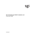
1
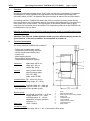
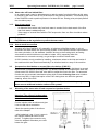
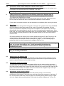
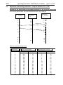
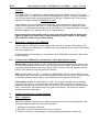
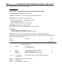
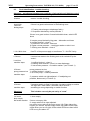
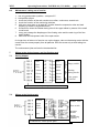
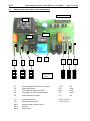
WDT
Operating Instructions PAKDOS 60 (V61-04/06)
Operating instructions PAKDOS - 60
page 1 von 22
WDT
Operating Instructions PAKDOS 60 (V61-04/06)
page 2 von 22
Table of Content
page
2
1.
Function
2.
2.1
2.2
2.3
2.4
2.4.1
2.4.2
2.5
Technical description
Framework with drum carrier
Powder dosing head
Suspensions- and flushing device
Control board PAK 60
Programmes
Supervision / external switch off
Demands to the quality of the carbon powder
3
3
4
5
6
6
7
7
3.
3.1
3.1.1
3.1.2
3.1.3
3.1.4
3.2
3.3
3.4
Mounting
Installation into the water circulation
Water take off before the filter
Water take off behind the filter - standard
Use of town water
How to avoid an overflow
Suspensions distribution to several filters
Mounting of the water take off and suspension injection
Electrical installation
9
9
9
9
10
10
10
4.
4.1
4.2
4.3
4.4
Taking into service
Water flow through the flushing tank
Water level adjustment
Adjustment of the spraying nozzles in the suspension device
Adjustment of the pump pressure switch
11
11
11
11
11
5.
5.1
5.2
5.3
5.4
Operation
Drum change
Adjustment of the dosing performance – Program switch on „B“
Back wash– isolation of the PAKDOS
Control of the PAKDOS by a timer / SPS / performance control
12
12
13
14
14
6.
6.1
6.2
6.3
6.4
Irritations indication – LED meaning
Short diagnosis
Irritations identification - short
Irritations identification – trouble shooting
Maintenance – taking out of service
15
15
15
16
18
7.
7.1
7.2
7.3
wiring plan - fuses
Connector housing dosing hopper
Connector housing flushing tank
Power plate with external control
18
18
18
19
8.
Maintenance protocoll
21
9.
Spare parts list
22
WDT
1.
Operating Instructions PAKDOS 60 (V61-04/06)
page 3 von 22
Function
By dosing powdered activated carbon (PAC) onto the filter the concentration of unwanted
and dangerous water ingredients as hydrocarbons and chlorinated hydrocarbons are
reduced to about 10-20%. At diatomite filter this technique is stand of the art (DIN 19643).
The dosing machine PAKDOS 60 meters the PAC by means of a dosing screw directly
from the container into a suspension device, from where the suspension is conveyed to the
filter system by a venturi nozzle. The high dilution of the carbon powder leads to good
mixing into the raw water flow to be treated. The suspension produced in the PAKDOS can
be distributed to up tu 4 filters.
Basis for an effective use of the PAC to improve the water quality is a good functioning filter
as to the DIN 19643.
Attention! The different powder qualities neeed very often different dosing screws for
good function. If there are problems, do not hesitate to contact us.
2.
Technical description
the dosing machine PAKDOS 60 consists of:
- Frame with turnable drum carrier
- Suspensions and flushing tank with
Venturi nozzle and booster pump
- Control unit
- Water tapping device
- Pneumatique valves (option)
- Suspensions distribution (option)
measures:
space app. 60x70 cm
heigh app. 146 cm
weight app. 50 kg
material:
steel, powder coated
other functional parts:
PVC, PE, ABS
seals: Viton, EPDM
container/drum: PE – drum 60 l (Euro)
filling weight 15 – 25 kg
dosing perform: Typ PAK 1200: 10 – 1200 g/h
Typ PAK 2500: 25 – 2500 g/h
Also dependent to the powder quality
Booster pump:
water flow:
Centrifugal pump 230 V / 0,33 kW
Supply pressure : 0,2 – 2 bar
counterpressure: 0 – 1,8 bar,
dependent on supply pressure
see para 3.1
1000 - 1500 l/h
1
2
3
4
5
6
7
8
9
drum
belts for fasten drum
drum ring for fasten dosing hopper
dosing unit
suspension unit
control system
locker for drum carrier
supporting stand
drum carrier
electrique supply:
mains plug 230 V +/- 6%, to be linked to filter pump,
WDT
2.1
Operating Instructions PAKDOS 60 (V61-04/06)
page 4 von 22
Standsäule mit Fassaufnahme
The rotating drum carrier assembly (9) is fixed to the main vertical support (8). The drum (1) with
PAC is fixed on the carrier assembly (6) by 2 band clamps (2). The dosing hopper (4) is fixed on
the drum in place of the drum lid by use of the spanning ring (3) of the drum. The carrier with the
drum is then turned through 180° to the dosing position, the chemical is dosed into the suspension
system (5) where it is fully suspended and conveyed by a venturi to the filter tubing.
2.2
Dosing head
1 dosing motor
11 drum seal
2 motor holder
12 wore plate for powder activation
3 moving screw for powder activation
4 connector for dosing tube heater 13 flat spring for powder activation
5 dosing screw
14 fitting plate for powder activation
6 guide tube for dosing screw 15 solenoid knocker (not shown)
7 seal tube
16 empty switch (not shown)
8 dosing tube heated
17 connector housing
9 cover for dosing hopper
18 cover for dosing motor
10 dosing hopper
The dosing head ist mounted onto the drum instead of the drum lid and fixed by using the
original spanning ring for the lid. An capacitive switch indicates “drum empty” through the
wall of the dosing hopper.
The powder is activated by a knocker that give every some seconds a stroke to the hopper
wall. To avoid condensation in the dosing tube (8) this is heated.
WDT
Operating Instructions PAKDOS 60 (V61-04/06)
page 5 von 22
The dosing performance is adjusted to the needs of the water treatment by adjusting dosng
cycles: At every start of a dosing cycle adjustable by the front switch S3 the dosing screw
runs for a certain time, to be adjusted by the front switch S4. The dosing performance is
very dependent on the quality of the powder. So the adjustment according to the table on
page 13 is only a thumb value. But at the end we have to adjust the dosing performance
according to the readings of the water quality. If the water quality is not good enough we
have to dose more, is it better than wanted, we can reduce the dosing.
2.3
Suspension system
For the function of the PAKDOS the pressure conditions are important. The limits are
described under para „Mounting, page 7.
At the standard type the suspension water comes from the circulation water behing the
filter. (supply pressure min. 0,2 bar). Behind the booster pump (26) the high pressure water
is distributed at the distribution part (27) via the floating valve (21) to the suspension tube
(28 - through the rain nozzles 28a) and flushing water through a side nozzle at the floating
valve and booster water to the venturi nozzle (25).
22a
21
28a
28
28a
21b
21a
29
32
31
22
20
31a
30
23
27
26a
20
21
21a
22
22a
23
24
25
26
26a
26b
26
pressure switch
floating valve
floater of floating valve
flushing tank
overflow
filter 300 for flushing water
flow switch
venturi nozzle
boster pump
pump connector suction side
1 ¼“ with gauge connector
25
24
26b
27
28
28a
29
30
31
31a
32
pump connector pressure side 1"
pressure water distribution PAK
suspensor
rain nozzles (2 pieces)
level switch
pressure washers (in union)
transparant detection tube with Opto-sensor (option)
gauge connector ¼“
isolation valve d25
The produced PAC-suspension is sucked off by the venturi (25) from the suspension tube.
The black powder is to be seen shortly after dosing in the transparent suction tube (with the
WDT
Operating Instructions PAKDOS 60 (V61-04/06)
page 6 von 22
flow switch 24) and the transparent detection tube with the optional available opto-sensor to
monitor the dosing function. The suction power of the venturi is adjusted at taking into
service by fitting a washer into the union behing the venturi nozzle: is the suction power too
high, use a nozzle with smaller hole, ist the suction power too low, use one with bigger hole.
A set of these washers is packed by to the machine. The pressure and flow situation is
monitored by the pressure switch (20) on top of the booster pump, level switch (29) in the
flushing tank and the flow switch (24) below the venturi. Dosing and also the booster pump
are switched off in case of any irritations situation. The irritation is indicated by the 4 red
LEDs at the front plate. The switch bobbin of the flow switch (24) functions as a non return
valve to avoid a high rate backflow of suspension from the flushing tank in case of switch
off. To avoid completely a backflow at switch off, e.g. at back wash of the filter, pneumatic
isolation valves may be installed in the supply and dosing tube.
Switching the PAKDOS through a timer watch and using the program BZ the tubing of the
PAKDOS is rinsed for 1 minute without dosing to clean the tubing.
2.4
Control system
The microprocessor based control system fitts three functions:
-
2.4.1
Dosing and test programmes with 3 switches
Functions and irritations identification by means of 1 green and 4 red LEDs
If an irritation occurs, the dosing is switched off automatically
Short diagnosis and function check
Programmes
4 test programmes to check the set dosing performance:
B 5:
B10:
B15:
B30:
dosing 5 minutes
dosing 10 minutes
dosing 15 minutes
dosing 30 minutes
After the end of the test the green LED is blinking
WDT
Operating Instructions PAKDOS 60 (V61-04/06)
K:
P:
page 7 von 22
knocker 1 minute all 4 seconds – no dosing
- only for authorised personal.
2 service programs:
B:
normal service program with continuous dosing
BZ:
service based on timer watch. Dosing is active, when the control input on conn.
S04,7-8 is closed. If the input is opened dosing is stopped, the booster pump is
running on for another minute to flush the dosing tubing. The green LED is blinking.
This program may be used for an external dosing control e.g. if a measuring system
for the combined chlorine is used. Within a cycle time of 1 minute dosing may be
activated from 1-60 seconds. See para 5.4
If changing a program dosing Stopps and the green LED blinks for 4 seconds.
2.4.2
Monitoring / external switch off
All functions are monitored. In the case of an irritation, dosing is switched off, the
irritation is indicated and identified by means of the LED. Dosing is indicated by flickering of
the LED 4. Remote fault control non volt is available – see wiring diagram para 6.
For daily switch off it is recommended to use the program BZ for timer control.
2.5
Needed specification of the carbon powder
there are a lot of different qualities of PAC on the market. They differ in the physical
properties as in the selectivity on the water chemicals. For a wanted effect on the water
quality with different PAC may be needed different dosing rates. So it may be necessary to
alter the dosing rates / the set values at the front plate even from 1 drum to another.
A high content of fine dust ore humidity may lead to blocking of the screw. Coarse grains
may block the suspension tube or the venturi nozzle.
Attention! Some qualities need special dosing screws. Please contact us if problems
with the dosing occurs.
3
Mounting
3.1
Installation of the PAKDOS into the water circulation
for mounting and operation a place of app. 1x1,5m is needed.
For a good function the pressure conditions are important.
So we use 2 booster pumps
for different pressure levels. For a low pressure level, e.g. preferred dosing before the
circulation pump, we use the pump HMS3 which may cover following pressure levels:
At supply pressure
1,2 bar
0,6 bar
0,3 bar
possible counter pressure
1,4 bar
1,1 bar
0,9 bar
for higher counter pressures we use the pump HMS4 with which pressures may be covered
WDT
Operating Instructions PAKDOS 60 (V61-04/06)
At supply pressure
1,2 bar
0,6 bar
0,3 bar
possible counter pressure
page 8 von 22
2,0 bar
1,8 bar
1,5 bar
To measure the existing pressures before and behind the booster pump there are hose
unions 6x1 to connect the water gauge supplied with the machine.
Attention! If the measuring water is taken from before filter and behind injection
point of the PAC you’ll get wrong – far too low - readings of free chlorine. The
measuring water take off must be before the injection point of the PAC!
3.1.1
Water take off between circulation pump and filter
respectively to the pressure conditions see before
1. water take off directly behind the filter pump before the non return valve
2. dosing behind the non return valve before injection of the flocculant but behind take off
of the probe water
3. pay attention to low pressure loss:
-
short distances
hose 1“ or tubing d25, for longer distances use bends instead elbows
only use the by-packed isolation valves
4. for the connections female threads 1“ are needed with no enclosers. The diameter of
the water take off tube is 26mm.
WDT
Operating Instructions PAKDOS 60 (V61-04/06)
page 9 von 22
3.1.2
Water take off from behind filter:
In an outdoor pool it may be advantageous to take the water from behind filter as this water
is cleaned by the filter. Here is only to be seen for the pressure situation. The booster pump
of the PAKDOS needs a positive pressure of at least 0,2 bar. Dosing point principaly before
the circulation pump.
3.1.3
Use of town water
Town water is used best
- at diatomite filters where only few fresh water is needed for the back wash of the filter
and fresh water is added anyhow.
- if the supply of several filters with the PAC suspension from one filter circulation makes
problems
Supply pressure min 3 bar. - mount a pressure control device
Pay attention to the regulation to protect the town water.
3.1.4
How to avoid an overflow
At switch off of the PAKDOS 60, especially at irritations of the filter system or only at
automatic filter back wash, the open flushing system of the PAKDOS remains connected to
the water circulation. As the standard isolation devices to the flushing tank, as floating
valve and flow switch bobbin are not able to isolate 100% (especially when the
maintenance is not made correctly), we get a slight overflow of black water.
A 100% isolation is only possible by installing membrane valves to the inlet and outlet of
the machine which are closed automatically if an irritation leads to a stop of the machine.
3.2
Suspensions distribution on several filter circulations (PAK SV)
The suspension produced by the PAKDOS 60 of app. 1000 l/h can be distributed to several
different filter circulations by dosing lines. The device consists of an isolation ball valve d25,
a flow meter 100-1000 l/h as a ball valve d20V to adjust the flow to the filter. For automatic
function we use pneumatic membrane valves which isolate all dosing lines at an irritation
event at one filter. A short interruption of the PAC dosing does not affect the general
cleaning effect of the PAC.
Water take off from behind the filter, dosing point before the circulation pump.
Never mount additional isolation valves to the system!
3.3
Mounting of the water take off and suspension injection device
Attention! The ellbow injection tubes
have a diameter of 26 mm. The female
threads must be free!
Cut the injection tube as shown and glue
it into the ball valve connection.
- Mark the opening side of the elbow
tube at the adapter.
- after hardening ( app. 1 hour ) screw in
the injection device as shown in the
picture. To tighten the connection only
seize the adapter! Otherwise you could
loosen the glue.
WDT
3.4
Operating Instructions PAKDOS 60 (V61-04/06)
page 10 von 22
Connection of the control cables to a central control board
For the fault remote and to control the machine you need for both a non volt contact to be
connected on the control plate of the PAKDOS - see para 7.
Principally use only flexible cables max. 0,52
4.
Taking into service / adjustment of the flushing system (see diagram page 5)
Dosing is switched off at the front plate, the valves at the tapping points are open.
The valves at the PAKDOS are closed.
Now open the inlet ball valve top of the filter. Water flows into the tank. When the tank is
half full, open the outlet ball valve at the machine and switch on the machine.
If town water is used the machine can be switched on immediately after opening all valves.
4.1
Water flow
A good water flow through the flushing tank is the basis of a good function of the PAKDOS..
this flow relates to the suction power of the venturi. By means of the washer (30) this
suction performance is adjusted to the pressure conditions. If the water level in the tank
falls steadily, the suction power is too big, you must fit a washer with a smaller bore. If the
level rises, you need a washer with bigger bore or use without washer. The switch bobbin of
the flow switch must be pressed up in the flow switch holder (24), the LED at the switch
must not burn.
Off works a washer with a 6mm bore is fitted, washers with bores 5,5 and 7mm are in the
spare parts kit in the by-pack. If there is no good flow possible, meter the supply and
counter pressure and compare with the table para 3, page 6. for this a water gauge is
packed by which is to be connected to the adapters 26a und 31a.
Attention! At the mounting works different particles may be fallen into the flushing
tank as cut parts from cable or pvc. Durch mehrmaliges Abdrücken des
Saugschlauches oder Schließen des Ablaufhahnes die Beweglichkeit des
Schaltkörpers prüfen.
Vibriert das Schwimmerventil am Arbeitspunkt, Schwimmerventil öffnen und den ORing am Ventilkegel abnehmen
4.2
water level in the flushing tank
A higher level you get by crewing out the floater (21a) a lower level by srewing it in. one
turn relates to app. 1 cm. Please adjust the level at the situation of good flow through the
tank to medium between level low and level high.
4.3
Adjustment of the rain nozzles
The suspension water to humidify the powder falling onto the water surface should rain
smoothly from the nozzles (28a). For adjustment you screw in or out the by-pass nozzle at
the outlet of the floating valve: comes the water from the rain nozzles too hard, open the bypass nozzle and reverse. If the water comes too hard, the fine dropplets may come up to
the dosing nozzle and this could be blocked.
4.4
Adjustment of the pressure switch
The pressure switch, fitted pressure side of the booster pump, is to monitor the
performance of the pump. If the pump runs well, there should be a pressure of at least 1,5
bar. If the pressure falls down, obviously there is something wrong with the pump: maybe
air in the supply tubing, anything broken. Off works the switch is adjusted to 1,5 bar. On
WDT
Operating Instructions PAKDOS 60 (V61-04/06)
page 11 von 22
operation the switch point can be changed by the adjusting screw from 1-3 bar. If changed,
it must be sure, that at any operating time the supply pressure is minimum 0,2 bar.
5
Operation
5.1
Drum change
As the powder can be compressed within the drum by vibration on transport and this could
make problems at dosing, please roll the drum on the floor before loading some times.
1. turn up the empty drum and take it off together with the the dosing head
2. open the new drum and take off the lid – let the spanning ring at the drum
3. position the dosing hopper on the open drum so that the cable is coming on right side
and fix it with the spanning ring.
In summer time the drum may be heated and the air in the drum may have a positive
pressure. So carfully open the drum.
Sicherungsblech am Klemmbügel einsetzen und umbiegen.
4. position the new drum on the carrier, so that the handle fits into the slide at the frame.
The drum must stand symmetrically on the drum carrier, touching the rear rails
5. Fix the drum securely in position using the drum band clamps. Adjust the clasp tension
by adjusting the nuts on the screwed end of the band clamps. Lock the clamp clasps
with the securing clips provided so that they cannot open by itself.
6. unlock the drum carrier swivel lock (7) and slowly rotate the drum and carrier left side
through 180°. Care should be taken not to stretch or entangle the cable joining the
hopper to the control box.
Lock the drum carrier in this position via the swivel lock right at the frame
7. Now push the sealing tube (7) over the suspension tube
the PAKDOS in the dosing position
WDT
5.2
Operating Instructions PAKDOS 60 (V61-04/06)
page 12 von 22
Adjustment of the dosing performance – Program switch on “B” or “BZ”
Diagram for the determination of the switch positions for the cycle and dosing time
100% dosing performance are at the PAKDOS 60/1200 app. 1200 g/h.
Schalterstellung
Cycle
Time
Zykluszeit
% fürswitch
pos.
%
Schalter S3
100 16
90
80
70 14
60
50
Dosing time
Schalterstellung
%für Dosierzeit
switch pos.
Dosing
Dosierleistung
Performance
%
%
%
100
80
60
40
PAKDOS 1200
12
100
90
80
70
60
16
50
10
20
8
PAKDOS 4000
5
20
30
20
6
4
2
6
10
9
8
7
6
12
8
10
30
14
40
40
10
Schalter S4
4
1
10
9
8
7
6
2
0,5
1
Table for cycle and dosing times
Schalterstellung
Switch pos.
1
2
3
4
5
6
7
8
9
10
11
12
13
14
15
16
Dosierzeit
Schalter S4
Zykluszeit
Cycle time
seconds
Sek.
493
411
342
285
238
198
165
138
115
95
80
66
55
46
38
32
dosing time seconds
%
6
8
9
11
13
16
19
23
28
34
40
48
58
69
84
100
Sek.
4
5
6
7
8
9
10
11
13
15
17
19
22
25
28
32
%
13
16
19
22
25
28
31
34
41
47
53
59
69
78
88
100
WDT
Operating Instructions PAKDOS 60 (V61-04/06)
page 13 von 22
Example:
The need of PAC is, depending on water quality actual and wanted, at app. 0.5-2 g/m³/h
circulated water. For the first we work with a dosing rate of 1 g/m³/h. At a filter circulation of
300 m³/h we would need a dosing performance of 300 g/h. These are 25% of the dosing
capacity of 1200 g/h having the PAKDOS 60/1200.
At the diagram you lay a straight line through 25% on the middle line meating a switch
position on the cycle time line, here 12. on the dosing time line the line meats the switch
position 11. All 66 seconds the dosing motor will work for 17 seconds as shown in the table
below the diagram. This setting is only for first approximation.
By measuring the water quality after 2-3 days you will find whether the dosing was
right, too high or too small. So you adjust the dosing rate by means of the dosing
time switch as needed to your water quality.
5.3
Back wash – isolation of the PAKDOS
At back wash the PAKDOS must be isolated from the filter to avoid a PAC-dosing to the
filter. If a suspension distribution is installed this is automatically done as the control valves
are closed for this time.
Doing the back wash manually you must switch off the PAKDOS and close the ball valves
at the PAKDOS.
5.4
Control of the PAKDOS by a switch timer / SPS / performance control
Switch timer: Program switch on „BZ“. Position the lever at the watch to the „watch“ sign.
For the wanted dosing time the timer levers must be pushed outside, At the end of the set
time dosing stops and the pump runs on for a further minute to flush the machine and the
tubing. In the switch off time the green LED flickers.
SPS: Program switch on „BZ“. To activate the PAKDOS the control contact (S04,7-8) is to
be closed. At the end of the set time dosing stops and the pump runs on for a further minute
to flush the machine and the tubing. In the switch off time the green LED flickers.
Performance control: Program switch on „BZ“. The switch for dosing cycle and dosing
time are to be set on 16. by pulsing the control contact (S04,7-8) within 1 minute every
wanted dosing performance from 0-100% can be set. If the control contact remains longer
than 1 minute open, the machine stops, the green LED flickers. By closing the contact
again the machine starts again.
6.
Irritation identification / trouble shooting
6.1
Short – diagnose
When the machine is switched on a diagnosis programme for the control equipment runs.
The same happens when the reset key is pressed.
1. All lights burn together 3 seconds
2. Each light comes on one after another for one second
3. If there is no fault, all red lamps go out and the dosing programme commences.
WDT
6.2
Operating Instructions PAKDOS 60 (V61-04/06)
page 14 von 22
LED Indicators for function and irritations
Grüne LED L0:
Green LED – indicates program switch and external inputs
on contiuously: GRANUDOS in operation
no light: Transformer Tr. 2 or fuse F1 for control system burnt
fast blink (0,5 second on, 0,5 second off...)
- programme knob not on a programme position
- end of test programme
- dosing switched off with front fascia switch
slow blink (2 seconds on, 2 seconds off)
External switch off e.g. by a central control on conn. S04-5
Flickering:
- dosing switched off on program BZ
- external switch off of dosing on connector S04-4
Red LED shows function of dosing and interruptions indicated by the different
Sensors. At any interruption dosing stops. Flickering of L4 shows that the dosing motor is
activated, the motor should run.
LED
happens
irritation
water level high
water flow too low
what
see below
2
L1
burns
L2
burns
water level low
pump pressure low
1
1
L3
L4
burns
burns
blink slow
counter pressure high (external)
dosing hopper empty
fuse F2 315 mAT – dosing motor
1
3
2
L1 + L4
L1 blink slow
L4 blink fast
fuse F3 800 mAT or power transformer faulty 1
Effect 1:
Effect 2:
Effect 3:
dosing stops, booster pump stops
dosing stops
only indication, no further
WDT
Operating Instructions PAKDOS 60 (V61-04/06)
6.3
page 15 von 22
Fault identification - trouble shooting
Attention – an indicated irritation may result by a fauly switch too! Switches out of
function if disconnected. Fault indication must go, if the switch is disconnected!
irritation
reason / trouble shouting
L1 burns:
Level high,
Flow low
dosing stops
It comes more water to the flushing tank as is sucked off
If there is a good suction down in the flushing cone:
1. Floating valve hangs or diaphragm faulty –
2. Suspensor blocked by coarse particles. I
If there is no good suction: flow switch bobbin down, switch LED
burns
3. booster pump blocked by big parts – dismantle and clean
4. prefilter blocked – clean it
5. particles in the venturi - dismount
6. higher counter pressure – use bigger washer or take it out
7. flushing cone blocked – clean it
L1+L4 blink slow
fuse F3 of the power supply or transformer Tr.1 24 VDC faulty
L2 burns:
it comes less water to the flushing tank as is sucked off by the
venturi,.
Level low,
machine stops
L2 burns
pump pressure low
1. prefilter blocked – clean it
2. floating valve blocked – clean it or new diaphragm
3. low counter pressure – fit smaller washer –(see. Para 4.1)
pump pressure too low
1. prefilter blocked – clean it
2. air in the pump – carefully deaerate
machine stops
3. pressure switch not right adjusted – if readjusting not
possible, disconnect (s. Punkt 4.4)
L3 burns:
machine stops
if pressure switch is fitted in the water circulation tubing to monitor
the right filter / back wash / automatic valve function:
something is wrong depending on switch function
Attention!
This irritation can only be put out by a “reset”
L 4 burns
drum empty
No further reaction
1. drum empty
If drum not empty: falls
2. empty switch to be new adjusted:
turn drum to top, take off the motor cover (18). Right side at the
hopper you see the square empty switch. By means of the small
screw driver you turn to right, till the switch LED burns then left till
LED is out, plus about 10°
WDT
Operating Instructions PAKDOS 60 (V61-04/06)
page 16 von 22
3. Empty switch is faulty – fit a new one
L4 blink slow
fuse F2 of the dosing motor 315 mAT burnt
1. dosing motor may be blocked by
- particles in the powder
- blocking of the powder in the dosing screw
- blocking of the dosing tube maybe by
humidity
In every case dismount the dosing motor with the screwThe screw
must have a very smooth surface. Clean dosing tube proper.
2. dosing motor faulty
L4 blinks fast
Option: if opical sensor is fitted to monitor the powder dosing:
For longer than 8 minutes no powder has been seen by the sensor.
1. reasons for that as above indicated
adjustment of the
opto sensor
(Carlo Gavazzi)
with clear water and clean transparent tube the switch LED must
burn. Turn adjusting screw to left till end (LED off) then again to right
till the LED burns + 10°
.
WDT
6.4
Operating Instructions PAKDOS 60 (V61-04/06)
page 17 von 22
Maintenance / taking out of service
1. use only good powder qualities – see para 2.5
2. hold prefilter proper
3. check the function of the rain nozzles more often, continuous, smooth rain
4. check the function of the monitoring switches
5. with every new drum or at least all 2 months clean the suspension tube and tank
properly by means of by-packed brush
6. at same time clean the heated dosing tube til the upper elbow by means of the small
round brush
7. every year change the diaphragm of the floating valve and the seal ring of the flow
switch bobbin
8. hold clean the transparent tube of the opto-sensor
for longer time of take out of service turn up the hopper, take out the dosing motor with the
screw clean the screw properly from all particles. Refit the screw only at next taking into
service.
The maintenance jobs are listed in the attached list.
7
Wiring at the dosing hopper and the flushing tank
7.1
Dosing hopper
Blue
Blue
Rose
brown
Grey
black
Yellow
white
Green
brown
White
White
brown
brown
Empty switch
Heating
dosing nozzle
- dos. motor
+ 24VDC
Connector no. on the power plate
The knocker is connected directly
7.2
Wiring at the flushing tank
Yellow
green
white
brown
grey
7.3
Leistungsplatine / Netzkarte
Connector no. on the power plate
level
min
switch max
flow switch
pressure
switch
dosing
monitoring
(option)
WDT
page 18 von 22
Wiring at the power plate, fuses, transformers
Flat cable
Tr. 1
Tr. 2
2
3
3
4
5
6
6
6
5
5
4
4
F1
F2
F3
F4
fuse for supply 230 VAC incl. knocker
fuse dosing motor
fuse all power outputs 24 VDC
fuse supply 6 VDC processor plate
1,25
315
800
315
Atr
mAtr
mAtr
mAtr
F0
mains fuse at front plate
6,3
Atr
Tr1
Tr2
power transformer
controller transformer
16 VA, 18 Volt
1,5 VA, 6 Volt
Rel.1
Rel.2
Rel.3
booster pump, solenoid valve
knocker
fault remote
1 2 3 4 5 6 7 8 9 10
1
2
3
1 2 3 4 5 6 7 8 9 10
1
2
1 2 3 4 5 6 7 8 9 10
1
Push conn.
coding
S 04
S 03
S 02
S 01
S 013
S 012
S 011
Rel. 2
S 010
7.3
Operating Instructions PAKDOS 60 (V61-04/06)
WDT
Operating Instructions PAKDOS 60 (V61-04/06)
page 19 von 22
connectors for 230 VAC 6 x 5 mm
push connector S010
push connector S011
1+2
3
4+5
6
1+2
3
4+5
6
230 V booster pump
PE
230 V control valve
PE
230 V reserve
PE
230 V reserve (booster pump)
PE
push connector S012
push connector S013 (4x5mm)
1+2
3
4
5
6
1+2
3
230 Volt mains
PE mains 230 volt
+205 VDC knocker (black1)
- 205 VDC knocker(black 2)
PE Klopfer
mains 230 Volt timer watch
PE
push connector 8 x 3,5 mm low voltage / non volt
push connector S01
push connector S02
fault remote non volt/ max 24V/ 8A
control cable from the dosing head
1
2
3
4-6
1
2
3
4-6
7
8
9
10
normally open
C-contact
normally closed
reserve
empty switch (inductive)
- 24 VDC empty switch
+24 VDC empty switch
reserve
- 24 VDC dosing motor
+24 VDC dosing motor
- 24 VDC heating dos. nozzle
+24 VDC heating dos. nozzle
push connector S03
push connector S04
control cable from the flushing tank
external controls
switches normally open, function to be
bridged to mass
1
2
3
4
5
6
7,8
9
10
reserve
- mass
water level in tank max, or flow low
dosing monitoring (option)
- mass
+ 24 VDC
reserve
water level in tank, pump pressure min.
- mass
1
2
3
4
5
6
7-8
counter pressure (ext.) max
pump pressure min
- mass
dosing off
PAKDOS off
- mass
switch timer for program BZ
(operation if switch is closed)
for the control cbles to the connector housing please only use flexible ones max 0,5²
WDT
8.
Operating Instructions PAKDOS 60 (V61-04/06)
page 20 von 22
Maintenance protocol PAKDOS 60
Objekt:......................................................................................................................................
PAKDOS type:...............................................................year:........................................
Maintenance executed on:............................................by:................................................
1
Subscription by the operator:....................................................................................
↓↓ This must be done!
Suspensions and flushing
1.1
check level switch:
OK
[ ]
change switch [ ]
1.2
check pressure switch:
OK
[ ]
change switch [ ]
1.3
check flow switch:
OK
[ ]
change switch [ ]
1.4
change flow switch diaphragm
[ ]
change bobbin [ ]
1.5
change floating valve diaphragm and O-ring
[ ]
1.6
check floating valve function
1.7
clean suspensor and flushing tank
[ ]
1.8
clean rain nozzles
[ ]
1.9
check slide ring seal
[ ]
1.11
clean pre-filter d75 and fine filter 300
[ ]
2
dosing head
2.1
function heating:
OK
[ ]
change heated nozzle [ ]
2.2
function empty switch:
OK
[ ]
change switch [ ]
2.3
current dosing motor: I max: 150+/- 30 mA
OK
[ ]
change motor [ ]
2.4
change seal of dosing motor
2.5
check and clean dosing screw
OK
[ ]
change
[ ]
2.6
check flat spring with wore plate
OK [ ]
change
[ ]
2.7
check knocker function
OK
change
[ ]
3
additional jobs
OK
[ ]
adjust water level [ ]
change [ ]
[ ]
[ ]
WDT
9.
Operating Instructions PAKDOS 60 (V61-04/06)
page 21 von 22
spare parts list PAKDOS 60
the positions nos. relate to the sketches on the indicated pages
1. dosing head page 4
Pos.
designation
article code no.
1
3
5
7
8
9
10
11
12
15
16
18
dosing motor PLG 30 - 60
moving srew PAK 24x16x85
dosing screw PAK d16,5 x140 with kit
sealing tube 125/70 on suspensor PAK
dosing nozzle PAK heated d25x100 PTFE
cover dosing hopper PAK
dosing hopper PAK 60 without techniques
seal 8x8 EPDM for dosing hopper, length 1,2m
wear plate PTFE for blade spring
knocker PAK complete
empty switch
motor protection cover PAK
11546
11779
11773
11783
11780
11760
11759
11534
11771
11764
10337
14046
2. suspensions and flushing system page 4
(19)
filter d75 GPL/PAK complete
filter insert d75 GR/PAK SS
O-ring filter top d75 EPDM
11804
11640
11258
20
21
pressure switch M10x1, 1-3 bar
floating valve d25 PAK complete
diaphragm kit for floating valve d25 GR/PAK
floater
elbow 3/8"-6x1 to floating valve
filter 1/2" 300u flushing water PAK
filter element 300µm SS
17275
11798
11619
11621
11616
11797
10482
24
24a
24b
24c
water flow monitoring with
flow switch holder 1/2" -S14 -US
flow switch 18x1 ind. for GR/PAK, lead 0,6m
flow switch bobbin 1/2" US
12729
11603
12730
25
26
venturi PAK 3/8" complete
booster pump Lo 2HMS4
booster pump Lo 2HMS3
slide ring seal Lo 2HMS 3/4-A
fitting booster pump Lo3/4 to venturi w/o filter
suspensor PAK (PE-tank)
rain nozzle PAK complete
level switch flushing tank 3/8" GR/PAK
orifice washers kit 5,5 - 6 - 7 mm
photoelectric switch, diffuse refl (option)
11591
10658
18181
12800
19813
11801
11803
10496
11594
10342
21a
21b
23
26c
27
28
28a
29
30
31
3. controlling page 6
cover control housing
locker Plexi for controller housing Vario Box
mains switch GR/PAK
12600
11967
11338
WDT
Operating Instructions PAKDOS 60 (V61-04/06)
mains fuse holder on front plate GR/PAK
turn key knob 4mm for control board MCU
12324
11757
5. control power plate page18
transformer board NTPAK-A flat cable
transformer power supply 240/18 volt -888 mA
transformer 240/6 volt 250 mA, 1,5 VA
11755
11665
10929
6. control plate
control board MCU 1c exchange part
fuses - set for GR 10-100 / PAK
12225
11752
page 22 von 22