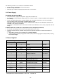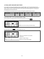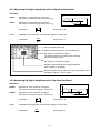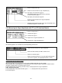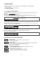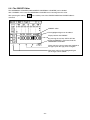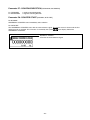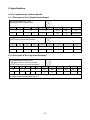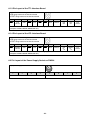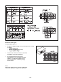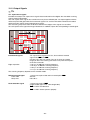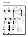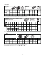
1
Operating Instructions Diagnostic Set 03/2003 Software 246 199-11 1. Contents 1. Contents ...................................................................................................................................................... 1 2. General Information....................................................................................................................................... 5 2.1 Safety Instructions................................................................................................................................. 5 2.2 Description of the PWM 8 Phase Angle Measuring Unit ....................................................................... 5 2.3 Functions of PWM 8 .............................................................................................................................. 5 2.4 Power Supply ........................................................................................................................................ 6 2.5 Items Supplied....................................................................................................................................... 6 2.6 Software ................................................................................................................................................ 7 2.7 Explanation of the Display..................................................................................................................... 7 2.8 Setting the Display Contrast................................................................................................................ 10 3. Operation..................................................................................................................................................... 11 3.1 Display after Power-On ....................................................................................................................... 11 3.2 Standard Soft-Key Row....................................................................................................................... 11 4. Description of the PWM 8 MODE................................................................................................................ 15 4.1 Switching the PWM 8 MODE .............................................................................................................. 15 4.2 PWM 8 MODE: UNIVERSAL COUNTER with Frequency Display ..................................................... 15 4.3 PWM 8 MODE: DETERMINE PULSE NUMBER with Frequency Display .......................................... 16 4.4 PWM 8 MODE: MEASURE U/I ........................................................................................................... 17 4.4.1 Display of the PWM 8 MODE: MEASURE U/I in the Mode Window........................................ 18 4.5 PWM 8 MODE: MEASURE AMPLITUDES ......................................................................................... 20 4.5.1 Measuring the Signal Amplitudes with 11µApp Interface Board: ............................................. 21 4.5.2 Measuring the Signal Amplitudes with 1Vpp Interface Board .................................................. 21 4.5.3 Measuring the Signal Amplitudes with TTL or HTL Interface Boards ...................................... 22 5. EXPERT MODE .......................................................................................................................................... 23 5.1 Activating the EXPERT MODE............................................................................................................ 23 5.2 Auxiliary Functions in the EXPERT MODE ......................................................................................... 23 5.2.1 The PRESET Editor ................................................................................................................. 24 5.2.2 The Parameters ....................................................................................................................... 25 5.2.3 Parameter Overview ................................................................................................................ 25 6. Practical Application .................................................................................................................................... 29 6.1 Power Supply of PWM 8 and Encoder ................................................................................................ 29 6.1.1 Power Supply of PWM 8 and Encoder via DC-IN Socket ........................................................ 29 6.1.2 Power Supply of PWM 8 and Encoder via the Encoder Output (OUT) of the Interface Board......................................................................................................................... 30 6.1.3 PWM 8 Power Supply via DC-IN Socket and Encoder Output (OUT) of the Interface Board......................................................................................................................... 32 6.1.4 Voltage Monitoring Function of Encoder Supply ...................................................................... 33 6.1.5 Block Diagram: PWM 8 Power Supply Unit ............................................................................. 35 7. Calibration ................................................................................................................................................... 36 -2- 8. Specifications .............................................................................................................................................. 37 8.1 Pin Layouts of the Interface Boards .................................................................................................... 37 8.1.1 Pin Layout of the 11µApp Interface Board ............................................................................... 37 8.1.2 Pin Layout of the 1Vpp Interface Board ................................................................................... 37 8.1.3 Pin Layout of the TTL Interface Board ..................................................................................... 38 8.1.4 Pin Layout of the HTL Interface Board..................................................................................... 38 8.2 Pin Layout of the Power Supply Socket on PWM 8 ............................................................................ 38 8.3 Specifications of PWM 8 Base Unit..................................................................................................... 39 8.4 Specifications of 11µApp Interface Board ........................................................................................... 40 8.5 Specifications of 1Vpp Interface Board ............................................................................................... 40 8.6 Specifications of TTL Interface Board ................................................................................................. 41 8.7 Specifications of HTL Interface Board................................................................................................. 42 8.8 Specifications of Power Supply Unit ................................................................................................... 42 9. Description of FST 2 Leak Tester................................................................................................................ 43 9.1 Explanation of the Controls and Displays ........................................................................................... 43 9.2 Example for Application....................................................................................................................... 44 9.3 Specifications of FST 2 ....................................................................................................................... 45 10. Description of ROD 450 Rotary Encoder .................................................................................................. 46 10.1 Specifications of ROD 450 ................................................................................................................ 46 11. Description of Connecting Cable 10-30V DC ............................................................................................ 46 12. Measuring Setup and Tolerances of the Output Signal............................................................................. 47 12.1 Description of the Output Signal ....................................................................................................... 51 12.1.1 Output Signals........................................................................................................................ 51 12.1.2 Output Signals........................................................................................................................ 52 12.1.3 Output Signals........................................................................................................................ 53 12.1.4 Output Signals........................................................................................................................ 55 13. Adapter Connectors .................................................................................................................................. 57 13.1 Overview of the Adapter Connectors ................................................................................................ 57 13.2 Adapter connector for exposed linear encode .................................................................................. 58 13.3 Adapter-connector for ERN 1387 ...................................................................................................... 59 14. Pin Layouts of Standard HEIDENHAIN Cables......................................................................................... 60 15. Description of the interface board, 1 Vpp, absolute (with Zn/Z1-track; EnDat/SSI; SSI-programmable) ................................................................................................................................... 64 15.1 General information........................................................................................................................... 64 15.1.1 1 Vpp measuring systems with Zn/Z1 track .......................................................................... 64 15.1.2 1 Vpp measuring systems with EnDat interface.................................................................... 65 15.1.3 1 Vpp measuring systems with SSI interface and 5V supply voltage ................................... 65 15.1.4 1 Vpp measuring systems with SSI interface and HTL supply voltage ................................. 66 15.1.5 1 Vpp measuring systems with programmable SSI interface................................................ 66 16 Items supplied ............................................................................................................................................ 67 16.1 Hardware........................................................................................................................................... 67 16.2 Adapter Cables overview .................................................................................................................. 67 16.3 Incremental Zn/Z1 ............................................................................................................................. 68 16.4 Absolute EnDat/SSI .......................................................................................................................... 69 16.5 Absolute EnDat/SSI motor encoder .................................................................................................. 70 -3- 17 Software Description .................................................................................................................................. 71 17.1 Required software version................................................................................................................. 71 17.2 Selecting the encoders via soft keys ................................................................................................. 71 17.2.1 Via the selection screen ......................................................................................................... 71 17.2.2 Via parameter P9 in the EXPERT MODE .............................................................................. 71 17.2.3 Switching the AB and CD tracks for 1Vpp encoders with Zn/Z1 ............................................ 72 17.3 1 Vpp measuring systems with programmable SSI interface........................................................... 73 17.3.1 Activating the menu for additional functions........................................................................... 73 17.3.2 Switching the encoder supply to HTL..................................................................................... 74 17.3.3 Parameter P10 "sensor connection" with programmable SSI encoders ................................ 75 18 Specifications: Interface Board 1Vpp, absolute.......................................................................................... 76 18.1 Encoder input (IN) ............................................................................................................................. 76 18.2 Encoder output (OUT) ....................................................................................................................... 76 18.3 Signal assignment of the BNC sockets ............................................................................................. 76 18.4 Measuring encoder current/voltage................................................................................................... 76 18.5 Measuring signal amplitudes............................................................................................................. 76 18.6 Display of /UaS interference signal .................................................................................................. 76 18.7 Terminating resistors......................................................................................................................... 76 18.8 Pin layouts of drive encoders and absolute encoders....................................................................... 77 18.8.1 1 Vpp measuring system with Zn/Z1 track ............................................................................ 77 18.8.2 1 Vpp measuring system with EnDat interface ..................................................................... 77 18.8.3 1 Vpp measuring system with programmed SSI interface .................................................... 78 18.9 Adapter kit for non-HEIDENHAIN wiring .......................................................................................... 79 18.9.1 Adapter kit 1 (Zn/Z1) for operation with Siemens and JH drives with HEIDENHAIN Zn/Z1 encoders and non-HEIDENHAIN wiring ................................................ 79 18.9.2 Adapter kit 2 (EnDat/SSI) for operation with Siemens drives with HEIDENHAIN EnDat/SSI encoders and non-HEIDENHAIN wiring ............. 80 18.10 Adapter cables for direct connection of PWM8 to the PCB connector of the encoder .................. 81 18.10.1 Adapter cable with 12-pin PCB connector ........................................................................... 81 18.10.2 Adapter cable with 14-pin PBC connector ........................................................................... 82 18.11 Adapter cable 17/17-pin; PWM to motor (Pos.Enc.EnDat) ............................................................ 83 18.12 Adapter cable to IK 115 interface card ........................................................................................... 84 18.13 Adapter cable 17/17-pin; PWM to motor (Mot.Enc.EnDat) ............................................................ 85 18.14 Adapter cable 17/17-pin; PWM to motor (Mot.Enc.EnDat) ............................................................ 86 18.15 Adapter cable 17/25-pin; PWM to subsequent electronics (Mot.Enc.1Vpp) .................................. 87 18.16 Adapter cable 17/25-pin; PWM to subsequent electronics (Mot.Enc.EnDat) ................................. 88 18.17 Adapter cable 17/17-pin; PWM to motor (Mot.Enc.EnDat) ............................................................ 89 Note: The successor is PWM 9, Id.Nr. 512 134-01. PWM 8 can be upgraded to PWM 9 by a hardware update. The upgrade is available for a fee! (More information: HEIDENHAIN Spare Parts Sales Phone: +49 (86 69) 31-31 22) -4- 2. General Information 2.1 Safety Instructions Do not put defective units into operation! 1. 0 2. I Fig 1: Connecting the PWM 8 in the position control loop of a machine tool controlled by TNC In order to correctly judge the problems in a machine tool controlled by TNC, fundamental knowledge of the machine tool and its drives as well as their interaction with the measuring systems is required. Inexpert handling may cause considerable damage and personal injury. HEIDENHAIN is not liable for any damage or personal injury caused directly or indirectly or by improper use or incorrect operation. Warning: Do not change any parameters or encoder voltages at the PWM while the machine tool is moving and a PWM is connected. 2.2 Description of the PWM 8 Phase Angle Measuring Unit The PWM 8 phase angle measuring unit is a universal measuring unit for inspecting and adjusting HEIDENHAIN linear and rotary encoders. The unit is operated by means of 5 soft keys. All values are displayed in a graphics display field. For each of the different encoder interfaces (11µApp, 1Vpp, TTL and HTL) a separate interface board is required. Each interface board is equipped with an encoder input (IN) and an encoder output (OUT). The unaltered scanning signals are available at the encoder output to be fed into e.g. a subsequent electronics. The PWM 8 may also be connected in series between the measuring system and the subsequent electronics. The axis functions of the machine tool are not impaired. It is also possible to use the PWM 8 separately for inspecting and adjusting measuring systems. 2.3 Functions of PWM 8 The main functions of PWM 8 are: • Display of phase angle and on-to-off ratio • Display of the scanning frequency • Measurement of signal amplitude, current consumption and supply voltage of the encoder • Display of the internal universal counter or the signal periods of a rotary encoder (pulse count) • Display of reference signal, fault detection signal and counting direction • Output of the amplified scanning signals (interface board: 11µApp, 1Vpp) or the original scanning signals (interface board: TTL, HTL) via 3 BNC sockets (e.g. to an oscilloscope) -5- The following functions are available in the EXPERT MODE: • Input of a preset for the internal universal counter • Encoder voltage selectable • Settings (e.g. dialogue language) programmable via parameters 2.4 Power Supply Possibilities of powering PWM 8 • Line-powered via a separate 24V power supply unit (standard set) • By an external, non-floating dc voltage source of 10 - 30 V / approx. 1 Ampere (adapter cable supplied with PWM 8). • Via the subsequent electronics; encoder, PWM 8 and subsequent electronics must be connected in series (Caution: power consumption of PWM 8 approx. 5.5W). The power supply of the measuring systems (external power supply unit or subsequent electronics) is selected via the soft keys of PWM 8. If a voltage is connected to the DC-IN socket of PWM 8, the PWM base unit is always operated with this voltage. If PWM 8 and/or the encoder are to be powered via the subsequent electronics, • the encoder monitoring function of the subsequent electronics is active; • it can be selected, how the encoder voltage of the subsequent electronics is fed to the encoder via PWM 8: 1. directly to the encoder (via parameter: P2 in EXPERT MODE) 2. via the switching regulator (integrated in PWM 8) with potential segregation and possibility of setting the encoder voltage. 2.5 Items Supplied Diagnostic Set Id.No. 312 431 01 Items Id.No. Id.No. 312 431 02 + + PWM 8 309 956 .. + Option FST 2 251 697 .. + Option ROD 450 295 455 A1 + + Power supply unit 313 797 .. + + Power cord 240V∼ 223 775 01 + + Adapter 10-30V DC 317 293 01 + + BNC cable (3 pcs.) 254 150 02 + + Connecting cable 9-pin 309 773-01 + + Connecting cable 12-pin 298 399-01 + + Operating instructions 312 737 .. + Option Interface board 11µApp 323 083 .. Option Option Interface board 1Vpp 323 077 .. Option Option Interface board TTL 323 079 .. Option Option Interface board HTL 322 732 .. Option Option Interface board Zn/Z1, EnDat, SSI 312 186 .. 1) 1) Description of the Interface board Id. Nr. 312 186 .. in section 15. -6- 2.6 Software For the PWM 8 phase angle measuring unit the following dialogues are available: Dialogue Software - Id.No. English / German 246 199-xx English / French 246 200-xx The last two places (xx) of the Id.No. represent the software version. 2.7 Explanation of the Display Information on the encoder Measuring range and scaling of the PHA/TV display PHA/TV display with peak hold (here: maximum error: +TV2) Display field for PWM 8 modes (here: UNIVERSAL COUNTER and frequency display) Soft-key row for operation Current assignment of the BNC sockets Structure of the display The following information is permanently displayed: a): Information on the encoder: Display: The supply voltage for the encoder is switched on. Display: The supply voltage for the encoder is switched off. Display: Reference signal (no reference signal available) The reference signal is displayed; no real-time display of the reference signal! Display: Fault detection signal (no fault detection signal generated) Fault detection signal generated, (active: low); at the same time the fault detection signal memory (ERROR) is set. No fault detection signal generated; the fault detection signal memory (ERROR) has been set by an earlier fault. The fault-detection memory can be deleted by: 1. activating another PWM 8 mode 2. switching the encoder voltage off and on 3. by pressing the soft key of the INFO soft-key row. Display of the counting direction: Encoder moves in forward direction Display of the counting direction: Encoder moves in backward direction -7- b): Measuring range and scaling of the PHA/TV display: Definitions: TV1, TV2 : On-to-off ratio incremental signal 1, incremental signal 2. At the zero crossover analogue incremental signals are triggered, i.e. converted into square-wave signals. One period (= on-time plus off-time of a square-wave signal) is subdivided into 360°. If on-time and off-time of a square-wave signal are the same, i.e. 180° each (180° + 180° = 360°), the on-to-off ratio is 0°. If the on-time of a square-wave signal exceeds the off-time, the on-to-off ratio is positive. An on-to-off ratio of e.g. +10° means the on-time of the square-wave signal is 190° (180° + 10°) and the off-time 170° (180° - 10°). PHA: Phase angle error between incremental signal 1 and incremental signal 2. If the incremental signal 1 leads the incremental signal 2 by 90°, the phase angle error is 0°. The phase angle error is the deviation from the optimum phase shift of 90° dimensioned in degrees. PHA/TV Display: PHA and TV are displayed as bars. The scaling of the PHA/TV display can be set for different measuring ranges. With automatic switch-over of the measuring range the (graduated) range of the PHA/TV display is automatically adapted to the biggest error (longest bar). Measuring range of the PHA/TV display (here ± 25°) With automatic switch-over of the measuring range the longest bar defines the measuring range. Symbol for automatic switch-over of the measuring range. Error display for: on-to-off ratio incremental signal 1 (TV1), on-to-off ratio incremental signal 2 (TV2), phase angle error between the two incremental signals (PHA) If the measuring range is exceeded with manual switch-over of the measuring range, an error is displayed. Switching over the measuring range: see standard soft-key row in section 3.2 Measuring range exceeded in negative direction Measuring range exceeded in positive direction Manual switch-over of the measuring range -8- c): Peak hold of the PHA/TV display: The peak hold holds and displays the maximum positive and negative value of the PHA/TV error. It can be deleted by selecting a MODE or if the measuring range is exceeded. With automatic switch-over of the measuring range, peak hold is not active for PHA/TV display. Display of positive peak hold Display of negative peak hold Manual start and stop of peak hold: If the peak-hold display is to be valid only for a certain measuring range, it can be started and stopped by hand. Manual operation is made by means of the MODE soft-key row: Soft key for manual control of the peak-hold display Soft key for manual start of the peak-hold display in standard operation. The already existing peak-hold display is deleted. After pressing the START soft key the STOP soft key is displayed. If this soft key is pressed, the peak-hold display is frozen and the bars of the PHA/TV display are hidden. Now the peak-hold display can be read. After pressing STOP, this soft key is displayed inverted which signals "frozen status". By pressing the inverted soft key, the peak-hold display switches back to its initial status (standard operation). d): Display field for PWM 8 MODE: All MODES are displayed in the MODE window: Headline MODE (here additionally: edge evaluation of the UNIVERSAL COUNTER)) Display field for the different MODES: • UNIVERSAL COUNTER • DETERMINE PULSE NUMBER • MEASURE CURRENT/VOLTAGE • MEASURE AMPLITUDES See section 4, Description of the PWM 8 MODES -9- e): Soft-key row for operation of PWM 8: The soft-key row makes PWM 8 easy to operate. It automatically configures itself according to the functions currently available. Example: Soft-key row after power-on: Standard setting of the soft-key row f): Display field for the current assignment of the BNC sockets A, B and C: This field contains the encoder signals currently fed to the three BNC sockets BNC A, B and C. 2.8 Setting the Display Contrast The contrast of the LC display of PWM 8 (Id.No. 309 956 X2) can be set from outside. The trimmer for contrast adjustment is located next to the BNC socket C. A trimming screwdriver is required to change the contrast. The contrast of PWM 8 units with the Id.No. 309 956 X1 can only be set internally. - 10 - 3. Operation 3.1 Display after Power-On Software-Id.No. 246 199-xx; the last two places symbolize the software version (here: version 01) Automatic recognition of the interface board (here: TTL interface) EXPERT MODE is active; see section 5 Software compensation data (for calibration by HEIDENHAIN staff) Note on software compensation data: The software compensation display is intended for calibration by HEIDENHAIN staff. The settings displayed can only be changed by HEIDENHAIN, Traunreut. 3.2 Standard Soft-Key Row After the power-on display, the standard soft-key row is displayed. Possibilities of setting the standard soft-key row: Switches to the soft-key row PWM 8 MODE (see PWM 8 MODE in section 4) Assignment of the BNC sockets A, B and C to different encoder signals; after pressing the BNC soft-key, you can choose from the following options: By pressing this soft key the BNC sockets A to C can be assigned to the encoder signals from memory 1 to 3. Terminate assignment of BNC sockets The default setting of the BNC memories made by HEIDENHAIN can be changed any time. - 11 - If e.g. the soft key BNC A is pressed, the assignment of the BNC socket A can be changed: Terminate BNC assignment Assignment of sockets B and C can be selected Arrow keys to change the encoder signals of the selected BNC socket A Switching the BNC memory: The assignment of the BNC sockets is stored in three BNC memories that can be called successively. Each time the soft key is pressed, the next BNC memory is activated. The display of the active BNC memory is highlighted: Changing the signals in the BNC memories 1 to 3: The signal in the active BNC memory is automatically stored each time it is changed by or . pressing the soft keys After power interruption the signals of the BNC memory active last are allocated to the BNC sockets. Notes on the use of the BNC sockets: • When using the BNC sockets to measure the encoder signals with an oscilloscope, be sure that the workstation and the operator are properly grounded! • A floating oscilloscope should be used to display the encoder signals with as little interference as possible. Always connect the oscilloscope to the socket of the switch cabinet of the machine tool to avoid signal distortions caused by different ground potentials. The following encoder signals can be connected with the BNC sockets: Interface Board Encoder signals on BNC socket BNC memory BNC A BNC B BNC C 11µApp Ue1 U1+2 Ue0 Ue2 U1+2 Ue0 Ue0 NTR /UaS *) 1 2 3 1Vpp A A+B R B A+B R R NTR /UaS *) 1 2 3 TTL, HTL Ua1 /Ua1 Ua0 Ua2 /Ua2 /Ua0 Ua0 /Ua0 /UaS 1 2 3 *) Signal is generated in the PWM 8. - 12 - Switching over the measuring range of the PHA/TV scaling. The following measuring ranges can be selected: The scaling currently selected is highlighted. When choosing automatic scaling (auto), the scaling is adapted to the biggest error (longest bar). This soft key serves to activate the Options soft-key row. The following functions are available: Terminate Options EXPERT-MODE; see section 5 The encoder can be powered INTERNALLY (by the power supply unit) or EXTERNALLY (by the subsequent electronics). Current setting: encoder powered INTERNALLY The power supply for the encoder can be switched ON and OFF. The terminating resistors for the scanning signals (with TTL or HTL and 1 Vpp interface board only) can be switched ON and OFF. The current setting is stored in PWM 8 and reloaded after power interruption. Interface board 0V +U encoder Switchable TTL 91 215 yes HTL 1200 1200 yes 1Vpp 11µApp 1) Terminating resistor [Ω] 121 yes 1) not available only possible with interface board Id.No. 323 077-XX or 312 246-01, index A The active setting is highlighted in the Options soft-key row. Note: is only displayed, if the PWM 8 is part of the encoder circuit, i.e. if a The soft key subsequent electronics (with encoder supply voltage) is connected to the encoder output of the interface board. - 13 - This soft key serves to display the Info soft-key row: Terminate INFO If more information is available, the PWM switches to the next INFO screen. The interfering signal memory (ERROR) can be erased The background lighting of the display can be switched on and off. Information on PWM 8 and on the interface board can be displayed on the INFO screen. Possible displays: Encoder voltage of the subsequent electronics too low to ensure proper function; see section 6: Practical Application 11µApp, 1Vpp, TTL or HTL interface board Terminating resistors for encoder signals: ON here: 200 Ω on + and 91 Ω on GND The supply voltage for the encoder is provided INTERNALLY (power supply unit). Counting direction of the UNIVERSAL COUNTER (here: backward counting when encoder moves in forward direction). The power supply of the encoder can be set to 10V max. without limit (except HTL); see section 3.2.2 Parameter Programming The UNIVERSAL COUNTER starts with the next reference pulse. With the interface board 11µApp the amplification of the output signals is indicated. The output signal of e.g. 11µApp is displayed as a 3.3 Vpp voltage signal at the oscilloscope. The EXPERT MODE has been activated (see section 3) The PRESET entered for the UNIVERSAL COUNTER is displayed. - 14 - 4. Description of the PWM 8 MODE 4.1 Switching the PWM 8 MODE After the power-on message, the standard soft-key row is displayed, from which the MODE soft-key row of PWM 8 can be called: Soft key to call PWM 8 MODE The following PWM 8 modes can be selected from the MODE soft-key row: Start/stop of peak hold Measure signal amplitudes Measure the current consumption of the encoder and the encoder voltage (and the sensor voltage) Determine the pulse count of the encoder (e.g. rotary encoder) and frequency display UNIVERSAL COUNTER with frequency display For each PWM 8 MODE the following auxiliary displays are active: (Description see section 2.7: Explanation of the display) • Display of the reference signal • Encoder monitor with memory function • Display of the counting direction • PHA/TV display • Assignment of the BNC sockets After power interruption the last active mode is loaded again. 4.2 PWM 8 MODE: UNIVERSAL COUNTER with Frequency Display The UNIVERSAL COUNTER counts the triggered edges of the incremental signals 1 and 2 of the encoder. Note: The function of the UNIVERSAL COUNTER is defined by the counter parameters P5 to P7. The UNIVERSAL COUNTER can be loaded with a preset. See section 5: EXPERT MODE, parameters and PRESET editor. MODE UNIVERSAL COUNTER with edge evaluation (see parameter P4) Display of universal counter Frequency display Sign - 15 - Clearing the UNIVERSAL COUNTER: The UNIVERSAL COUNTER is cleared by pressing the soft key a second time. Frequency counter: The frequency counter operates up to a frequency of 2 MHz. The frequency is derived from the incremental signal 1. 4.3 PWM 8 MODE: DETERMINE PULSE NUMBER with Frequency Display The MODE DETERMINE PULSE NUMBER is intended to find the pulse count of a rotary encoder. The parameter P5: EDGE EVALUATION is automatically set to 1-fold, the parameter P6: COUNTING MODE to 0-1-2! MODE DETERMINE PULSE NUMBER Pulse number (line count) Frequency display Proceeding to determine the pulse count: First reference signal starts the pulse counter Break of approx. 1 second (= display time of the pulse count) Display of intermediate pulse counts Next reference signal stops the pulse counter Display of the pulse count Each time "DETERMINE PULSE NUMBER" is activated, the pulse counter is reset, i.e. the next reference signal starts the counter, the next but one stops it. This function can be of use e.g. when operating with measuring systems with distance-coded reference marks. - 16 - 4.4 PWM 8 MODE: MEASURE U/I The PWM MODE: MEASURE U/I the current consumption and the power supply of the encoder can be measured. Depending on the interface board also the sensor voltages can be measured as well. In the subsequent electronics the sensor lines serve to tap the encoder voltage directly at the encoder at high resistance and to feed it back to the subsequent electronics. Voltage drops on the supply lines of the encoders are then compensated in subsequent electronics offering compensation. TTL, HTL and 1Vpp encoders are equipped with sensor lines. If an error is detected during measurement of the sensor voltages, a blinking error field is displayed in MODE: MEASURE U/I. Error display during measurement of the sensor voltage A sensor-voltage error is displayed, if: + sensor smaller than 90 % of U-MSYS, or - sensor larger than 10 % of U-MSYS Note: In the PWM 8 MODE: MEASURE U/I the supply lines of the encoder and the sensor lines are separated, whereas in all other PWM 8 MODES they are connected to each other! The current consumption of the terminating resistors (with TTL and HTL interface boards) is displayed together with the current consumption of the encoder. I.e. even if no encoder is connected, the current consumption of the encoder is displayed, if the terminating resistors and the encoder supply voltage are switched on. - 17 - 4.4.1 Display of the PWM 8 MODE: MEASURE U/I in the Mode Window Depending on the power supply of the encoder and of PWM 8, the MODE MEASURE U/I may be displayed differently in the MODE window: MODE: MEASURE U/I of encoders with sensor lines (TTL, HTL, 1Vpp interface boards): • and internally powered encoder (= via power supply unit) or • externally powered encoder and parameter: P2 U-MSYS EXTERN = FLOATING Floating power supply of the encoder with relation to the subsequent electronics. Current consumption of the encoder Power supply of the encoder (here: floating) Sensor lines of the encoder Special feature of HTL interface board: A floating power supply of the encoder is not possible. The parameter P2 has no function. The MODE MEASURE U/I is displayed as follows with HTL interface board: Special feature of HTL interface board: The encoder is powered by the power supply unit (= internally) without potential segregation. • externally powered encoder and parameter: P2 U-MSYS EXTERN = FROM CUSTOMER The encoder is powered directly by the subsequent electronics without potential segregation. Current consumption of the encoder Power supply of the encoder (here: customer voltage) Sensor voltages of the encoder - 18 - MODE: MEASURE U/I of encoders without sensor lines (11µApp interface boards): • und interner Meßsystemversorgung (= aus Externem Netzteil) oder • externer Meßsystemversorgung und Parameter: P2 U-MSYS EXTERN = POTENTIALFREI Floating power supply of the encoder with relation to the subsequent electronics. Current consumption of the encoder Power supply of the encoder • externer Meßsystemversorgung und Parameter: P2 U-MSYS EXTERN = VON KUNDE The encoder is powered directly by the subsequent electronics (customer) without potential segregation Current consumption of the encoder Note: No potential segregation between encoder and subsequent electronics Power supply of the encoder (= customer voltage) - 19 - 4.5 PWM 8 MODE: MEASURE AMPLITUDES In this mode the vertices of the amplitudes of the incremental signals 1 and 2 are measured. The result always refers to an individual signal period. With sinusoidal encoder signals (11µApp and 1Vpp) the positive and the negative vertices are measured versus U0, with square-wave encoder signals (TTL and HTL) low and high level are measured versus 0V. In the table below the maximum measuring ranges are listed for the different interface boards: Interface board: 11µApp 1Vpp Maximum measuring range 33 µApp 1.66 Vpp TTL HTL low: 0 – 2.5 V high: 2.5 – 7.5 V low: 0 – 7.5 V high: 7.5 – 22.5 V If the EXPERT MODE is active (see section 5) and the 11 µApp or 1Vpp interface board used, the encoder supply voltage can be set in the mode MEASURE AMPLITUDES: For this purpose the standard soft-key row has been expanded by the soft key . Soft key to switch to setting of encoder voltage After pressing the soft key the encoder voltage can be set: Soft key to switch back to the standard soft-key row Display of encoder voltage Soft keys to set the encoder voltage - 20 - 4.5.1 Measuring the Signal Amplitudes with 11µApp Interface Board: Definitions: I SYM.1: Symmetry 1, ratio of positive to negative half wave of incremental signal Ie1 (versus U0) a 0 SYM.2: Calculation: I1 / I2: a-b c t b Symmetry 2, ratio of positive to negative half wave of incremental signal Ie2 (versus U0) Result: ideal = 0 2´c Amplitude ratio, amplitudes of incremental signals Ie1 versus Ie2 Calculation: CIe1 Result: ideal = 1 CIe2 Result is displayed in µApp Datum for measurement of sign. amplitude (U0) Bar display of incremental signal 1. The position of the bars stands for the symmetry of the incremental signals. Bar display of incremental signal 2. Range for measurement of the signal amplitude; here: 33 µApp (± 16.5µApp) Numerical peak-to-peak value of the signal amplitudes of the incremental signals 1 and 2 in µApp. 4.5.2 Measuring the Signal Amplitudes with 1Vpp Interface Board Definitions: U SYM.A: Symmetry A, ratio of positive to negative half wave of incremental signal A, (versus U0). a 0 SYM.B: Calculation: A / B: b Symmetry B, ratio of positive to negative half wave of incremental signal B, (versus U0). a-b Result: ideal = 0 2´c Amplitude ratio, amplitudes of incremental signals Ie1 versus Ie2 Calculation: CA Result: ideal = 1 CB - 21 - t c Result is displayed in Vpp. Datum for measurement of sign. amplitude (U0) Bar display of incremental signal A. The position of the bars stands for the symmetry of the incremental signals. Bar display of incremental signal B. Range for measurement of the signal amplitude; here: 1.66 Vpp Numerical peak-to-peak value of the signal amplitudes of the incremental signals A and B in Vpp. 4.5.3 Measuring the Signal Amplitudes with TTL or HTL Interface Boards Result is displayed in V Incremental signal 1 Incremental signal 2 High level of a signal amplitude in V Low level of a signal amplitude in V The following options are available in the corresponding soft-key row: Terminate measurement of signal amplitudes Switch the BNC memory for BNC sockets A to C Switch to inverted signals Switch terminating resistors on and off (defined load of the square-wave signals). The highlighted option is active. Special feature of HTL interface board: Up to software version 05: With HTL encoders the inverted signals may not be available depending on the encoder. Check whether the inverted signals are available before measuring the signal amplitudes. PWM 8 cannot recognize, whether there are inverted signals or not! If the inverted signals are missing, incorrect values are displayed for the signal amplitudes! From software version 05: If the encoder does not provide inverted signals, "------" is displayed for the signal levels of the inverted signals. - 22 - 5. EXPERT MODE In addition to the standard functions PWM 8 offers further possibilities in the EXPERT MODE: • Input of a PRESET • Possibility of adjusting the encoder voltage • Parameter programming 5.1 Activating the EXPERT MODE The EXPERT MODE is activated by pressing the left and the right soft key while the power-on screen is displayed. is displayed. The message: With parameter P4: SAVE EXPERT MODE the activation of the EXPERT MODE can be automated. After the power-on screen the standard soft-key row is displayed: Press soft key: OPT. After pressing the soft key OPT. (OPTIONS) in this soft-key row, the OPTIONS soft-key row is displayed. From there you can switch to the EXPERT MODE. Press soft key: EXPERT MODE When pressing the soft key EXPERT MODE, the following options are displayed. Soft-key row of the EXPERT MODE: 5.2 Auxiliary Functions in the EXPERT MODE Reduce U-MSYS: The power supply of the encoder can be reduced to approx. 3V (HTL interface board: 10V). Increase U-MSYS: The power supply of the encoder can be increased to approx. 6V (HTL interface board 19V when operating with an external 24V power supply unit). See parameter P3: U-MSYS Limit Activating the PRESET editors: In the PWM 8 MODE: UNIVERSAL COUNTER a PRESET can be entered. Activating PARAMETER programming The PWM 8 can be configured by means of parameters. To terminate the EXPERT MODE press the soft key ESC. - 23 - 5.2.1 The PRESET Editor The UNIVERSAL COUNTER (PWM 8 MODE: UNIVERSAL COUNTER) can be loaded with a PRESET. In this case the UNIVERSAL COUNTER starts counting from this value. After pressing the soft key: activated. in the soft-key row of the EXPERT MODE the PRESET editor is PRESET editor The highlighted figure can be edited. Display field for the PRESET By pressing the soft key SET P-SET the displayed PRESET is transferred into the UNIVERSAL COUNTER. These soft keys serve to move the highlight to the figure (or to the sign) to be changed. With these soft keys the highlighted figure (or the sign) can be edited. - 24 - 5.2.2 The Parameters By means of parameter programming several PWM 8 settings can be changed. After pressing the soft key in the soft-key row of the EXPERT MODE, the menu for parameter programming is displayed. When commissioning PWM 8 the parameter default setting is as follows: Current parameter setting Terminate parameter programming All parameters are reset to their default values (fig.: parameter default setting) The highlighted parameter can be changed by pressing the soft key CHANGE By pressing these soft keys the highlighted field can be moved to the parameter to be edited. If parameters are changed, PWM 8 internally stores the changes. When the PWM 8 is switched on again, the stored parameter values are loaded. If parameter values have been stored that are different from the standard setting and the EXPERT MODE is not active, the standard setting can be loaded from the Options soft-key row. However, the parameter P1 Dialogue is not changed. With this soft key the parameter default setting can be loaded in the Options soft-key row. 5.2.3 Parameter Overview Parameter P1: Dialogue Language [GERMAN, ENGLISH] [GERMAN, FRENCH,] Software Id.No.: 246 199 xx Software Id.No.: 246 200 xx The dialogue of PWM 8 can be switched. Possible language combinations are German/English and German/French. - 25 - Parameter P2: U-MSYS EXTERN [FLOATING, FROM CUSTOMER] Note: Parameter P2 is only effective, if the encoder is powered externally (= by a subsequent electronics, e.g. a counter, a control or customer electronics). In this case PWM 8 can be switched to EXTernal power supply of the encoder in the Options soft-key row: Soft key to switch to EXTernal power supply of the enocder. This soft key is only displayed, if an encoder voltage of a subsequent electronics has been connected to the encoder output of the interface board. Shown setting: encoder is powered externally. If the encoder is powered EXTERNALLY, parameter 2 serves to choose whether the encoder supply of the subsequent electronics is to be • floating with relation to PWM 8 (potential segregation) (parameter setting: FLOATING), or • directly fed to the encoder without being changed by PWM 8 (parameter setting: FROM CUSTOMER). Special feature of HTL interface board: When using a HTL interface board, parameter P2 is not available. The measuring system can only be powered with the potential of the subsequent electronics. Potential segregation is not possible! Why is potential segregation required between PWM 8 and subsequent electronics? Owing to different reference potentials of the encoder signals 11µApp/1Vpp (U0) and the interface boards (0V) the signals may be shifted, which can cause counting errors in the subsequent electronics and in the most unfavorable case result in a measuring circuit error. Potential segregation avoids signal shifts and ensures that the encoder circuit operates correctly, when PWM 8 is switched on. Notes on floating encoder supply from the subsequent electronics: (Parameter P2: FLOATING) 1. To ensure trouble-free functioning of subsequent electronics with 11µApp and 1Vpp encoder inputs. 2. In the PWM 8 the power supply of the encoder is generated by a switching regulator, providing 5.0V (standard setting) irrespective of the encoder power supply of the subsequent electronics. If required, the encoder voltage can be set manually. For this purpose the soft keys available. in the soft-key row of the EXPERT MODE are Note on HTL interface boards: When using a HTL interface board the standard setting of the encoder voltage is 12V, if there is no supply voltage of the subsequent electronics at the OUT flange socket of the interface board. If there is a voltage, PWM 8 "connects" the HTL encoder voltage to the encoder voltage of the subsequent electronics. With HTL interface boards potential segregation is not possible. 3. The current intensity of the encoder voltage is set to 500 mA; if the terminating resistors (with TTL and HTL interface boards) are switched on, it is 700 mA. 4. Owing to potential segregation the power consumption of the encoder supply by the subsequent electronics is approx. 50% higher than it would be without potential segregation (due to the efficiency of the DC/DC converter and the switching regulator). Please also note the increased voltage drop on the encoder supply line caused by the higher current intensity! - 26 - Notes on encoder supply directly from the subsequent electronics: (Parameter P2: FROM CUSTOMER) 1. Trouble-free functioning of subsequent electronics with 11µApp and 1Vpp encoder interfaces cannot be guaranteed due to signal shifts of the subsequent electronics! 2. The encoder voltage of the subsequent electronics is fed directly to the encoder without being changed by PWM 8; it cannot be altered. 3. There is no current limitation for the encoder voltage. 4. The power consumption of the subsequent electronics for the encoder supply is only slightly higher than that of the encoder. About 10 mA are required for the voltage monitor of the subsequent electronics. Parameter P3: U-MSYS LIMIT [ON (6 VOLTS), OFF (9 VOLTS)] Parameter P3 defines the maximum limits for the encoder voltage. By switching off the U-MSYS limit the encoder voltage can be set in the range of 9V ±1V. Caution: The measured object may be destroyed by overvoltage! Standard encoders are operated with a voltage of 5V ± 5%. Special feature of HTL interface boards: When using the HTL interface board, parameter P3 is not available! In the EXPERT MODE the encoder voltage can only be set with the soft keys parameter P2 is set to FLOATING. if the Parameter P4: EXPERT MODE [NOT SAVE, SAVE] If parameter P4 is set to SAVE, the EXPERT MODE is reactivated after power interruption; if it is set to NOT SAVE, the EXPERT MODE must be reactivated each time power is switched on. Parameter P5: EVALUATION [1-FOLD, 2-FOLD, 4-FOLD] In parameter P5 the edge evaluation of the UNIVERSAL COUNTER (PWM 8 MODE UNIVERSAL COUNTER) is set. It defines how many edges per signal period of incremental signal 1 and incremental signal 2 are transferred to the UNIVERSAL COUNTER and used for measurement of the frequency. In the PWM 8 MODE: DETERMINE PULSE NUMBER the evaluation is automatically set to 1-FOLD. The EVALUATION is displayed next to the headline of the UNIVERSAL COUNTER: Display of edge evaluation of the universal counter (here: 1-FOLD) Parameter P6: COUNTING MODE [0-1-2, 0-2-4, 0-5-0] Parameter P6 defines the COUNTING MODE of the last digit of the UNIVERSAL COUNTER. - 27 - Parameter P7: COUNTING DIRECTION [FORWARD, BACKWARD] P7: FORWARD P7: BACKWARD = positive counting direction = negative counting direction Parameter P8: COUNTER START [NORMAL, WITH REF] P8: NORMAL UNIVERSAL COUNTER starts immediately after selection. P8: WITH REF The UNIVERSAL COUNTER starts with the next reference signal. The current count is frozen until the first reference mark is reached. This "time-out" is marked by the symbol in the display field of the UNIVERSAL COUNTER. Symbol for "timeout": start with the next reference signal - 28 - 6. Practical Application 6.1 Power Supply of PWM 8 and Encoder 6.1.1 Power Supply of PWM 8 and Encoder via DC-IN Socket In general PWM 8 and the encoder can be powered from different sources. The table below contains an overview of possible power supplies: PWM 8 powered from 24 V power supply unit subsequent electronics directly from floating subs. electronics 1) x only 24V power supply unit connected (DC-IN socket) x only voltage from subsequent electronics connected (encoder output) x 24 V power supply unit and voltage of subsequent electronics connected 1) Power supply of encoder x 1) x x x x 1) When using a HTL interface board, potential segregation is not possible. As already mentioned in section 2 "General Information", PWM 8 may either be powered by the 24V power supply unit (standard set) or another dc voltage source of 10 - 30 V via the DC-IN socket. The voltage at the DC-IN socket is referenced to the encoder voltage generated by PWM 8, i.e. if potential segregation is required between PWM 8 and subsequent electronics, the voltage at the DC-IN socket must be floating with relation to the subsequent electronics. The 24V power supply unit supplied with PWM 8 complies with this requirement. If the PWM 8 is operated via the DC-IN socket, it is always powered from this current source, irrespective of whether an encoder voltage is fed at the encoder output of the interface board or not. PWM 8 detail 5 Socket for external power supply (see section SPECIFICATIONS) 8 7 6 4 3 2 1 - 29 - Basic circuit diagram of the power supply of the encoder with the power supply unit connected: G mFm"dG zp§F¤zzd© pFm4p=F¤zzd© 4pm¦FF §a4^amVFV¤d"p§a^p¤ zpFma"dFVFV"apm p§F¤zzd©¤ma The standard setting of the encoder power supply is 5V; when operating with HTL interface board without subsequent electronics 12V. Current consumption of PWM 8 when powered via DC-IN socket: (measured with 11µApp interface board) Voltage at DC-IN 10 V 12 V 15 V 20 V 24 V 30 V PWM 8 current consumption 500 mA 420 mA 350 mA 270 mA 230 mA 200 mA PWM 8 current consumption with encoder (100 mA) 580 mA 480 mA 400 mA 310 mA 260 mA 220 mA 6.1.2 Power Supply of PWM 8 and Encoder via the Encoder Output (OUT) of the Interface Board PWM 8 can be integrated into the encoder circuit. For this purpose the subsequent elec-tronics must be connected to the encoder output (OUT) of the interface board. The supply voltage for PWM 8 is taken from the subsequent electronics. In order to reduce the power consumption of the subsequent electronics, the background lighting of the display is auto-matically switched off! Basic circuit diagram of the power supply of encoder and PWM 8 with subsequent electronics connected (with interface board 11µApp, 1Vpp, TTL): G 4pm¦FF §a4^amVFV¤d"p ""h¢ pFma"d FVFV"apm Odp"amV Oph 4¤phF - 30 - pFm4p=F¤zzd© ¤*F¤FmFdF4pma4 sskzz:szz: mFm"dG zp§F¤zzd© Basic circuit diagram of the power supply of encoder and PWM 8 with subsequent electronics connected (with HTL interface board): 4pm¦FF pFm4p=F¤zzd© G mFm"dG zp§F¤zzd© ¤*F¤Fm FdF4pma4 Current consumption of PWM 8 powered by subsequent electronics: (measured with 11µApp interface board) Supply voltage at interface board OUT 4.5 V 4.8 V 5V 5.2V PWM 8 current consumption (without background lighting) 1.15 A 1.05 A 1.0 A 0.95 A PWM 8 current consumption with encoder (100 mA) 1.4 A 1.25 A 1.2 A 1.15 A From the table can be seen that PWM 8 and encoder can only be powered by subsequent electronics equipped with power supply units with large power reserve. Note: When using (long) connecting cables between the subsequent electronics and PWM 8 the voltage drop may be considerable (current on the line to and from the encoder) which additionally reduces the voltage of the subsequent electronics! In the PWM 8 MODE: MEASURE AMPLITUDES the current consumption from the subsequent electronics is approx. 0.4 A higher! Note: If parameter P2: U-MSYS EXTERN is set to FLOATING, potential segregation and the switching regulator in PWM 8 can be switched off by setting P2 to FROM CUSTOMER. This reduces the power consumption from the subsequent electronics (see section 5.2.2, PARAMETERS, Parameter P2). When using the HTL interface board, parameter P2 is not available and potential segregation not possible! - 31 - Voltage monitoring function of PWM 8 power supply: If the voltage of the subsequent electronics falls below 4.8V, a warning is displayed: Warning: The voltage of the subsequent electronics is too low to power PWM 8! The encoder supply was switched off to be on the safe side. Press this soft key to ignore the warning. When this warning appears, we recommend to power PWM 8 via the power supply unit. The warning can be ignored, if desired. It is then no longer displayed (however a warning is displayed in the INFO MODE). After power interruption the voltage monitor is reactivated. To be on the safe side, the encoder supply is switched off. The operator must reactivate it in the OPTIONS soft-key row. Afterwards, trouble-free functioning of PWM 8 can no longer be guaranteed and must be observed by the operator 6.1.3 PWM 8 Power Supply via DC-IN Socket and Encoder Output (OUT) of the Interface Board If the 24V power supply unit and the subsequent electronics are simultaneously connected, PWM 8 is always powered by the 24V power supply unit. In the OPTIONS soft-key row the power supply of the encoder can be selected: The encoder can be powered INTernally (by the 24V power supply unit) or EXTernally (by the subsequent electronics) (current setting: INTernally) Basic circuit diagram of power supply of encoder and PWM 8 with 24V power supply unit and subsequent electronics connected (with interface board 11µApp, 1Vpp, TTL): G p§F¤zzd©¤ma ¤*F¤FmFdF4pma4 sskzz:szz: mFm"dG zp§F¤zzd© §a4^amVFV¤d"p ""h¢ pFma"d FVFV"apm Odp"amV _ Oph 4¤phF - 32 - pFm4p=F¤zzd© 4pm¦FF Basic circuit diagram of power supply of encoder and PWM 8 with 24V power supply unit and subsequent electronics connected (HTL with interface board): G p§F¤zzd©¤ma mFm"dG zp§F¤zzd© §a4^amVFV¤d"p§a^p¤ zpFma"dFVFV"apm ¤*F¤FmFdF4pma4 pFm4p=F¤zzd© 4pm¦FF _ Note on HTL interface boards: If the encoder voltage of the HTL interface board is set to INTERNAL and at the same time a subsequent electronics connected to the OUT flange socket of the interface board, the switching regulator in PWM 8 tries to set (clamp) the encoder voltage to that of the subsequent electronics. PWM 8 is not permanently adjusted to the encoder voltage of the subsequent electronics; it is only adjusted when the PWM 8 is switched on, when the encoder voltage is switched on or off or the encoder supply is set to INTERNAL. If there is no subsequent electronics connected, the switching regulator provides 12V in the standard setting. With the HTL interface board potential segregation of voltage, subsequent electronics and encoder voltage is not possible. 6.1.4 Voltage Monitoring Function of Encoder Supply If the encoder supply is set to EXTERNAL and parameter P2 U-MSYS EXTERN set to FLOATING, PWM 8 checks the voltage of the subsequent electronics. In order to switch the encoder voltage to EXTERNAL the subsequent electronics must at least provide the power-on current for potential segregation and for the switching regulator. If this is not the case, the following message is displayed: This soft key serves to confirm the message. The encoder supply is reset to INTERNAL Note: If parameter P2 U-MSYS EXTERN is set to FLOATING, the potential segregation and the switching regulator in PWM 8 can be switched off by setting P2 to FROM CUSTOMER. This reduces the power consumption from the subsequent electronics (see section 5.2.2 PARAMETERS, Parameter P2). When using the HTL interface board, parameter P2 is not available. Potential segregation is not possible in this case. - 33 - If in the OPTIONS soft-key row the encoder supply is set to EXTERNAL and parameter P2 U-MSYS EXTERN to FLOATING, PWM 8 checks the voltage of the subsequent electronics. If the voltage drops to approx. 4.5V trouble-free functioning of potential segregation and switching regulator can no longer be guaranteed; a warning is displayed: Warning: The voltage of the subsequent electronics is too low to power the encoder. The power supply of the encoder has been switched off to be on the safe side. The warning can be ignored by pressing this soft key Press this soft key to switch the encoder supply to INTERNAL and clear the warning When this warning is displayed, the encoder supply must be switched to INTERNAL. The warning can be ignored, if desired. In this case the warning is no longer displayed. (However a warning is displayed in the INFO MODE). To be on the safe side, the encoder supply is switched off. The operator must reactivate it in the OPTIONS soft-key row. Afterwards, trouble-free functioning of PWM 8 can no longer be guaranteed and must be observed by the operator. If the voltage of the subsequent electronics falls below 3V, another warning is displayed requesting the operator to switch the encoder supply to INTERNAL: Press this soft key to switch the encoder supply to INTERNAL - 34 - - 35 - subsequent electronic with HTL measuring system supply : steering, counter ... subsequent electronic with 5 V measuring system supply : steering, counter ... power supply 24 V protection against excess voltage, low voltage, polarity reversal suppressing coil protection against low voltage, polatity reversal 0V rel.3 1 MOhm GND* HTL/5 V GND* V-out 3..9 V with 5 V 10..25 V with HTL adjust voltage : I-max: 500 mA 700 mA V-in GND switching conv. (step-down) GND* GND* I2C-bus U-MSYS INT/EXT rel.1 0 V subsequent electronic GND* +12 V* floating potential internal currentlimit: 1250 mA 4.5 - 10 V DC/DC-converter microcontroller I/O port U-MSYS INT/EXT rel.1 microcontroller I/O port I2C-control rel.3: 0V-connection on/off rel.2: (= parameter P2 ) U_MSYS from customer / floating rel.1: U-MSYS int / ext 0V-subsequent elec. GND* microcontrollerboard with 80C552 backlight on/off GND* U-MSYS EXTERN: floating potential rel. 2 = parameter P2 U-MSYS EXTERN: from customer U-measuring-sys HTL U-measuring-sys 5V GND* GND* floating potential +12 V* +12 V* -12 V* +5 V* +5 V* -18 V* LCD-drive backlight for LCD -12 V* rel. 2 = parameter P2 0V IN -18 V +5 V backlight for LC-display DC/DC- converter 10 - 30 V backlight on/off 6.1.5 Block Diagram: PWM 8 Power Supply Unit 7. Calibration In general no maintenance is required for PWM, since there are no components that are subject to wear. However, to ensure reliable and trouble-free operation we recommend to send your PWM 8 including the interface boards (especially 11µApp and 1Vpp) every 2 years to HEIDENHAIN, Traunreut for calibration. Note: Calibration of the PWM always includes a software upgrade! - 36 - 8. Specifications 8.1 Pin Layouts of the Interface Boards 8.1.1 Pin Layout of the 11µApp Interface Board 9-pin HEIDENHAIN flange socket at IN flange socket of interface board 1 2 5 I1 + 6 7 8 I2 – I0 + – 3 4 9 5V 0V 0V UN internal shield + – UP 7 8 3 4 9 5V 0V free UP UN 9-pin HEIDENHAIN flange socket at OUT flange socket of interface board 1 2 5 I1 + 6 I2 – I0 + – + – 8.1.2 Pin Layout of the 1Vpp Interface Board 12-pin HEIDENHAIN flange socket at IN flange socket of the interface board at OUT flange socket of the interface board 5 6 8 A + 1 3 B – + 4 R – + – 12 10 2 11 9 7 5V 0V 5V 0V free free UP UN sensor sensor The sensor lines are connected to the corresponding supply lines (exception: PWM 8 MODE: MEASURE U/I). - 37 - 8.1.3 Pin Layout of the TTL Interface Board 12-pin HEIDENHAIN flange socket at IN flange socket of the interface board at OUT flange socket of the interface board 1 2 3 4 5 6 7 8 9 10 12 11 Ua2 +5 V sensor Ua0 Ua0 Ua1 Ua1 UaS Ua2 chassis 0V UN +5 V UP 0V sensor The sensor lines are connected to the corresponding supply lines (exception: PWM 8 MODE: MEASURE U/I). 8.1.4 Pin Layout of the HTL Interface Board 12-pin HEIDENHAIN flange socket at IN flange socket of the interface board at OUT flange socket of the interface board 1 2 3 4 5 6 7 8 9 10 12 11 Ua2 10-30 V sensor Ua0 Ua0 Ua1 Ua1 UaS Ua2 chassis 0V UN 10-30 V UP 0V sensor The sensor lines are connected to the corresponding supply lines (exception: PWM 8 MODE: MEASURE U/I). 8.2 Pin Layout of the Power Supply Socket on PWM 8 8-pin power supply socket DC-IN 8 7 6 5 2 1 2 3 4 4 3 1 5 10-30V 6 7 0V - 38 - 8 8.3 Specifications of PWM 8 Base Unit Power supply PWM 8: • at DC-IN socket: Power supply: Current consumption of PWM 8 without encoder: 10 - 30 V approx. 230 mA (5.5 W) with 24 V power-on current approx. 1 A approx. 15 W Current consumption with power supply unit: • at OUT flange socket of the interface board: Power supply: 3 - 10 V (11µApp, 1Vpp, TTL) 10 - 30 V (HTL) Current consumption of PWM 8 without encoder: approx. 1.0 A (5 W) with 5 V Power supply of the encoder by PWM 8: Note: Parameter P2: U-MSYS EXTERN set to FLOATING Encoder voltage (11µApp, ,1Vpp, TTL) 3 - 9 V selectable standard setting: 5 V ± 0´.1 V Encoder voltage (HTL) (without voltage of subsequent electronics) 10 - 19 V with 24 V power supply unit 10 - 25 V with 30 V at DC-IN standard setting: 12 V ± 0.2 V 10 - 19 V with 24 V power supply unit tolerance ± 0.5 V Encoder voltage (HTL) („clamp“ to voltage of subsequent electronics) Encoder current Encoder current with termin. resistor switched on: 500 mA max. 700 mA max. Frequency display: Measuring range of the frequency counter: 20 Hz - 2 MHz Frequency range of the universal counter: Maximum input frequency approx. 2 MHz Bar display PHA, TV1, TV2: Measuring ranges in degrees [ ° ]: 5, 10, 20, 50, autom. measuring range standard setting: ±50° 10 Hz - 10 MHz 10 Hz - 10 kHz ± 0.5 degrees 10 kHz - 500 kHz ± 2 degrees 500 kHz - 1 MHz ± 3 degrees Frequency range: Error PHA/TV display: (for interface board TTL, HTL) Error PHA/TV display: (for interface board 11µApp, 1Vpp) (Note: The offset adjustment of the trigger on the interface board must have been carried out!) Temperature range: Operating temperature Storage temperature 10 Hz - 10 kHz 10 kHz - 500 kHz 500 kHz - 1 MHz 0 °C - + 40 °C - 20 °C - +60 °C - 39 - ± 1 degree ± 2.5 degrees ± 3.5 degrees 8.4 Specifications of 11µApp Interface Board mV mA Signal amplification (Ie1, Ie2, Ie0): 300 Input amplifier: Maximum signal current: Ie0, Ie1, Ie2: 66 µApp Maximum frequency at encoder input: -3 dB: approx. 300 kHz Note: The maximum input frequency only stands for the cutoff frequency of current/voltage converter in PWM 8 (signal source: frequency generator). In real operation with encoders the frequency highly depends on the photocells and their capacitance, as well as on the cable lengths. Measure current/voltage: Measuring range current: Measuring range voltage: Tolerance: 0 - 500 mA 0 - 10 V ±3% Measure amplitudes: Measuring range: Measuring frequency: Tolerance: without adjustment via software: with adjustment via software: 2 µApp - 33.3 µApp (0.6 - 10 Vpp) 10 Hz - 50 kHz ±5% ±3% Fault detection signal: Ie1 and Ie2 < 4 µApp Encoder output: Output signal: like input signal without U0 8.5 Specifications of 1Vpp Interface Board Input amplifier: Maximum signal voltage: ± 5 Vpp Maximum frequency at encoder input: for encoder voltage on interface board: for signals on BNC sockets (- 3dB): approx. 500 kHz approx. 1 MHz Note: Input frequencies over 1 MHz are possible; however, the tolerance of the PHA/TV display can no longer be guaranteed! The maximum input frequency only stands for the cutoff frequency of the voltage input of PWM 8 (signal source: frequency generator). In real operation with encoders the frequency highly depends on the encoder and on the cable lengths. Measure current/voltage Measuring range current: Measuring range voltage: Tolerance: 0 - 500 mA 0 - 10 V ±3% - 40 - Measure amplitudes: Measuring range: Measuring frequency: Tolerance: without adjustment via software: with adjustment via software: ±5% ±3% Terminating resistance: 121 Ω Fault detection signal: A and B < 0.3 Vpp Encoder output: Output signal: like input signal with U0 0.2 Vpp - 1.6 Vpp 10 Hz - 50 kHz 8.6 Specifications of TTL Interface Board Maximum input voltage: Maximum input frequency: ± 7V approx. 2 MHz Note: The maximum input frequency only stands for the cutoff frequency of the square-wave input at PWM 8 (signal source: frequency generator). Measure current/voltage: Measuring range current: Measuring range voltage: Tolerance: 0 - 500 mA 0 - 10 V ±3% Measure amplitudes: Measuring range high level: Measuring range low level: Resolution: Measuring frequency: Tolerance: 2.5 - 7.5 V 0 - 2.5 V 50 mV 10 Hz - 200 kHz ± 50 mV Terminating resistance: From encoder signal to U-MSYS From encoder signal to GND 215 Ω 90,9 Ω Special feature of TTL interface board: Owing to the input wiring, the PHA/TV display works properly even in the case of a cable break. The missing signals are generated internally and output at the encoder output. Cable breaks can be found in the mode "Measure Signal Amplitudes" or by checking the encoder signals at the BNC sockets. - 41 - 8.7 Specifications of HTL Interface Board Maximum input voltage: Maximum input frequency: 0 - 30 V approx. 2 MHz Note: The maximum input frequency only stands for the cutoff frequency of the square-wave input at PWM 8 (signal source: frequency generator). Measure U/I: Measuring range Measuring range Tolerance: current: voltage: 0 - 500 mA 0 - 30 V ±5% Measure amplitudes: Measuring range high level: Measuring range low level: Resolution: Measuring frequency: Tolerance: 17.5 - 22.5 V 0 - 7.5 V 100 mV 10 Hz - 200 kHz ± 100 mV Terminating resistance: From encoder signal to U-MSYS From encoder signal to GND 1200 Ω 1200 Ω Special feature of HTL interface board: If the inverted are missing at the encoder output, they are generated internally and output at the encoder output. 8.8 Specifications of Power Supply Unit Input voltage: Output voltage: Protection grade: Maximum ambient temperature: 100 - 240 V ac, 50 - 60 Hz 24 V dc, 1.0 A 1 40 °C - 42 - 9. Description of FST 2 Leak Tester The leak tester serves to check NC-linear encoders and rotary encoders with sinusoidal output signals and 9-pin connector for leak circuits (up to 3 MΩ) at the cabling and the photocell board. The FST2 is switched on automatically as soon as a test piece (e.g. a linear encoder) is connected. The current conduction through the lamp (LED) of the encoder is used for testing. When testing equipment without a lamp (e.g. an extension cable or if the lamp is defective) the automatic test is not active. In this case the button "Start man." must be pressed. Encoders with integral pre-amplifiers can only be tested for leak circuits between internal shield ( ) and external shield( ). Owing to the internal resistance of the pre-amplifier (< 3 MΩ) the remaining 4 LEDs always indicate a leak circuit when a test unit is connected. 9.1 Explanation of the Controls and Displays 1 Input socket, 9-pin: For connection of measuring systems with sinusoidal output signals and extension cables with 9-pin connector. 2 Manual start button: When testing equipment without lamp/LED or encoders with defective lamp/LED the manual start button must be pressed to activate the FST2. The leak tester is then active as long as the button is pressed. The manual start button also serves to test the battery. The battery voltage is in order, if the LEDs light up in a sequence like a running light as long as the button is pressed. 3 LED display: Leak circuits are displayed by permanently lit LEDs. The LED running light indicates that there is no leak circuit in the test piece. The figure on the FST2 housing indicates the location of the leak circuits. 4 Brief operating instructions Brief operating instructions in German are printed on the rear side of the leak tester. A sticker in English language is supplied with FST2. - 43 - 9.2 Example for Application Testing a rotary encoder showing the following defects (leak circuits): 1. leak circuit between and 2. leak circuit between Ie1 and 0V/5V Instruction Display Error Cause Battery test: press manual start button Running light = battery o.k. LEDs dark = defective battery Connect rotary encoder; test starts automatically! Leak circuit is displayed between and (1. leak circuit). Test is not started. (LEDs dark) Light unit of the rotary encoder defective or connection to light unit interrupted. Press manual start button; test is started. Leak circuit is displayed between and (1. leak circuit) Eliminate leak circuit in rotary encoder! The running light stops at the "0V/5V" LED. The leak circuit between 0V/5V and Ie1 is indicated by the LEDs 0V/5V and Ie1 permanently lit. (2. leak circuit) Connect rotary encoder; test starts automatically. Eliminate 2. leak circuit in rotary encoder! Each of the 6 LEDs lights up for a moment (running light) as long as the rotary encoder is connected or the manual start button pressed. No leak circuit in the rotary encoder! Connect rotary encoder; test starts automatically. After repair the test must be repeated until all LEDs light up like a running light. Then there is no leak circuit in the test piece! - 44 - 9.3 Specifications of FST 2 Sensitivity: leak circuits ≤ 3MΩ Test sequence 1. 2. 3. Ie0 4. Ie2 5. 0V/5V 6. Ie1 Test cycle 1 second Power supply 9 V monobloc battery Exchange the batteries every 2 years; use leak-proof trademarked batteries (e. g. Alkaline) Battery voltage ≥ 5.5 V Below 5.5 V the tester is inoperative! Current consumption 10 mA (in operation) ≤ 0.1 µA (quiescent current) Cable lengths (depend on capacitance) - 45 - 10. Description of ROD 450 Rotary Encoder The ROD 450 serves to test counting function and interpolation of ND, VRZ, IBV EXE etc. Moreover, it is suited to preset the oscilloscope trigger for checking the reference mark with PWM 8. 10.1 Specifications of ROD 450 Power supply 5V ± 5%/85 mA Output signals Incremental signals Ie1 / Ie2 7 ... 16µApp Reference signal Ie0 2 ... 8 µA (usable component) Line count 1000 lines/revolution 1 ref. signal/ revolution Cable length 1m 11. Description of Connecting Cable 10-30V DC farbig/coloured The connecting cable serves to power the PWM externally with 24V dc (e.g. control voltage of the machine tool). Note: The potential of the control voltage must be separated from the encoder voltage. measuring circuit error may occur without potential segregation. - 46 - 12. Measuring Setup and Tolerances of the Output Signal Example: Checking sinusoidal output signals Equipment required for adjustment: a) Oscilloscope (2 channels) b) PWM 8 c) Interface board for 11 µApp or 1 Vpp Connection of a linear encoder to an oscillloscope via PWM 8 A B C IN OU T - 47 - Analog Output signals (~ 11 µApp/1 Vpp) Prepare the oscilloscope as described below: • Vertical deflection – Switch channels A and B to chop mode (CHOP). – Set the deflection coefficient (Sensitivity) of the channels A and B to 0.5 V/DIV (11µApp), 0.2 V/DIV (1Vpp). • Horizontal deflection – Set time coefficient (Time basis) to 0.5 ms/DIV. • Triggering – Trigger automatically (AUTO) – Trigger Channel A – Trigger positive edge • Calibration – Switch the input coupling switch (AC/DC/GND) of the channels A and B to GND (ç or 0) – Use the Y-position potentiometers of the channels A and B to shift the electron rays congruently to the center of the screen (fig.) – Switch the input coupling switch (AC/DC/GND) of the channels A and B to DC . PWM 8 Settings analog signals BNC [°] MODE BNC A Ue1 (A)* BNC B Ue2 (B)* 25° Measure amplitude * Interface board 1 Vpp Possible oscilloscope display x - t or x - y - 48 - Reference mark signal Oscilloscope display x - t • Change the trigger setting of the oscilloscope basic setting as follows: – Trigger channel A – Manual triggering (AC or DC) – Trigger negative edge • Traverse the reference mark to be checked oscillatorily (“forward“/“backward“). • At the oscilloscope turn the trigger potentiometer to set the trigger threshold (LEVEL) such that the reference mark signal is depicted as “stationary“ image on the screen. Note: Schematic display of Ue1+2 on the oscilloscope. The actual amplitude is higher than displayed. - 49 - PWM 8 Settings reference mark BNC BNC A Ue0 (A)* BNC B 1+2 (A+B)* * Interface 1 Vss * Old LS series: LS 50x; LS 80x (e.g. LS 503; LS 803) I0 = 5 ... 15µAss Schematic display of I1+I2 (A+B) on the oscilloscope. Example: Reference mark signal Caution: The reference-mark edges (ref. Mark / Uo line) must not intersect outside the tolerance range! Note: The quality of the output signals has an influence on the measuring accuracy of the linear and rotary encoders. The tolerances stated are valid for standard applications of HEIDENHAIN encoders (e.g. LS on machine tools with measuring steps up to 1 µm). For operation with encoders with higher accuracy (e.g. exposed, contactless encoders, angle encoders and encoders with highly interpolated output signals) the tolerances for the output signals are smaller. HEIDENHAIN compares precision encoders to a measuring standard after adjustment. - 50 - 12.1 Description of the Output Signal 12.1.1 Output Signals 11 µApp Current signals The sinusoidal incremental signals I1 and I2 are phase-shifted by 90°; their level is approx. 11 µApp. The peaks of the ref. mark signals I0 have a usable component of ca. 5.5 µA. The current signal of the incremental linear encoders can be interpolated and digitized either in the subsequent electronics, e.g. HEIDENHAIN ND position display or TNC numeric control or in a separate HEIDENHAIN EXE interpolation and digitizing electronics. For current signals the maximum cable length between linear encoder and subsequent electronics is 30 m provided that original HEIDENHAIN cables are used. Incremental signals 2 sinusoidal signals I1 and I2 signal amplitude* I1, I2: 7 to 16 µApp Reference mark signals 1 or several peaks I0 signal amplitude with 1 kΩ load I0 ca. 5.5 µA (usable component) * These values apply for Up = 5 V ± 5% at the source, cable lengths up to 30 m and a cross-section of the power supply line of 1 mm². The signal amplitude changes with increasing scanning frequency. Recommended input circuit of the subsequent electronics Example: Cable length Max. 30 m (distributed capacitance 90 pF/m) when using original HEIDENHAIN cables -3dB cutoff frequency of input circuit approx. 60 kHz Dimensioning Differential line receiver RC4157 C = 27 pF R = 100 kΩ ± 2% U0 = UB/2 UB = +15 V - 51 - 12.1.2 Output Signals 1Vpp Voltage signals The sinusoidal incremental signals A and B are phase-shifted by 90°; their level is approx. 1 Vpp. The peaks of the ref. mark signals have a usable component of ca. 0.5 V. Encoders with a Z1 track additionally output the signals C and D. The specification of these signals is identical to that of the incremental signals (see section 13, adapter connector). When using original HEIDENHAIN cables, voltage signals can be transferred over a distance of 150 m to the subsequent electronics. For this purpose a supply voltage of 5 V ± 5% or 5 V ± 10% (depending on the encoder model) must be ensured at the encoder. Encoders that output voltage signals feature connectors for the sensor lines which serve to measure the supply voltage at the unit. By means of appropriate controlling means in the subsequent electronics the tolerance of the supply voltage can be observed. Sinusoidal voltage signals can be highly interpolated. Output signals measured with PWM 8 Incremental signals 2 sinusoidal signals A and B signal amplitude* approx. 1Vpp A, B: 0.6 to 1.2 Vpp with terminating resistor Z0 = 120 Ω Reference mark signal 1 or several peaks R signal amplitude approx. 0.5 V R: 0.2 to 0.8 V (usable component) with terminating resistor Z0 = 120 Ω * These values apply for Up = 5 V ± 5% or Up = 5 V ± 10% at the encoder. The signal amplitude changes with increasing scanning frequency. Recommended input circuit of the subsequent electronics Example: Cable length Max. 150 m (distributed capacitance 90 pF/m) when using original HEIDENHAIN cables -3dB cutoff frequency of input circuit approx. 100 kHz Dimensioning Differential line receiver RC4157 R1 = 10 kΩ and C1 = 220 pF R2 = 34,8 kΩ and C2 = 10 pF UB = ± 15V - 52 - 12.1.3 Output Signals TTL TTL square-wave signals Encoders that output TTL square-wave signals feature electronics that digitize the sinusoidal scanning signals without interpolation. Two TTL square-wave signals Ua1 and Ua2 that are phase-shifted by 90° are output together with the reference pulse Ua0 gated with the incremental signals Ua1 and Ua2. Encoders with distance-coded reference marks output several Ua0 reference pulses. The measuring step results from the distance between two edges of the signals Ua1 and Ua2. To each square-wave signal the integral electronics in addition outputs the corresponding inverted signal. Incremental signals TTL square-wave signal trains Ua1, Ua2 and their inverted signal trains Ua1 and Ua2 . Ua2 lags Ua1 with ccw rotation (view on shaft or on encoder flange) or when the scanning unit moves away from the ID plate of the linear encoder. Edge separation a ≥ 0.4 µs at 400 kHz scanning frequency a ≥ 0.45 µs at 300 kHz scanning frequency a ≥ 0.8 µs at 160 kHz scanning frequency a ≥ 1.3 µs at 100 kHz scanning frequency The scanning frequency depends on the encoder model. Reference mark signal Pulse width Delay time 1 square-wave pulse Ua0 and its inverted pulse Ua0 90° elec. Itdl ≤ 50 ns Fault detection signal 1 square-wave pulse UaS (single-ended signal: max. cable length 50m) UaS = LOW: fault detected UaS = HIGH: device operates properly - 53 - TTL signal level Load capacity Switching times UH ≥ 2.5 V with −IH = 20 mA UL ≤ 0.5 V with IL = 20 mA − IH ≤ 20 mA IL ≤ 20 mA CLoad ≤ 1000 pF Rise time: t+ ≤ 100 ns Fall time: t− ≤ 100 ns The fault detection signal UaS indicates a malfunction, such as break of a supply line, lamp failure etc. TTL square-wave signals can be transferred over cable lengths up to 300 m to the subsequent electronics. For this purpose a supply voltage of 5 V ± 10% (for RAN 460: range between 10 and 30 V) must be ensured at the linear or rotary encoder. In the subsequent electronics TTL square-wave signals can be interpolated 100-fold max. by means of phase-locked control loops. Recommended input circuit of the subsequent electronics Recommended differential line receivers AM 26 LS 32 MC 3486 SN 75 ALS 193 SN 75 ALS 195 We recommend not to exceed the cable length related to the scanning frequency, since otherwise the switching times resp. the edge gradient cannot be maintained. - 54 - 12.1.4 Output Signals HTL HTL square-wave signals The design of encoders with HTL square-wave signals is similar that of encoders with TTL square-wave signals. Output signals are HTL square-wave pulse trains Ua1 and Ua2 together with the reference pulse Ua0 that is gated with the incremental signals Ua1 and Ua2. To each square-wave pulse train the integral electronics in addition outputs the corresponding inverted signal (not with ERN 1030). The outputs of encoder with HTL square-wave signals are short-circuit proof at room temperature. Incremental signals: HTL square-wave pulse trains Ua1 and Ua2 and their inverted pulse trains Ua1 and Ua2 (ERN 1030: no inverted pulse trains). Ua2 lags Ua1 with ccw rotation (view on shaft or encoder flange). Edge separation a ≥ 0.45 µs at 300 kHz scanning frequency a ≥ 0.8 µs at 160 kHz scanning frequency The scanning frequency depends on the encoder model and can be seen from the specifications. Ref. mark signal Pulse width Delay time Fault detection signal 1 square-wave pulse Ua0 and its inverted pulse Ua0 ERN 1030: no Ua0 90° elec. Itdl ≤ 50 ns for gated ref. pulse 1 square-wave pulse UaS UaS = LOW: fault detected UaS = HIGH: encoder operates properly (short circuit not permissible after Up) Signal level HTL Load capacity Switching times ERN 1030: no fault detection signal UaS UH ≥ 21 V with −IH = 20 mA UL ≤ 2.8 V with IL = 20 mA if supply voltage is +24 V, without cable − IH ≤ 200 mA (not true for UaS ) IL ≤ 200 mA CLoad ≤ 1000 pF Rise time: t+ ≤ 200 ns Fall time: t− ≤ 200 ns - 55 - HTL square-wave signals can be transferred over cable lengths up to 300 m (ERN 1030: 100 m) to the subsequent electronics (PLC etc.). We recommend not to exceed the cable length related to the scanning frequency and to the power supply, since otherwise the switching times resp. the edge gradient cannot be maintained. In the subsequent electronics HTL square-wave signals can be interpolated 100-fold max. by means of phase-locked control loops. If the cable is longer than 50 m, the 0V signal lines must be connected to 0V of the subsequent electronics to increase noise immunity. The permissible cable length depends on the scanning frequency and on the power supply. - 56 - - 57- ROD ROD ROD Meßsystem Encoder oder 11µAss 11µApp Meßsystem TTL Encoder TTL oder Meßsystem 1Vss Encoder 1Vpp ohne Z1-Spur oder Stecker, AdapterAdapter connector 15-/9pol. Id.-Nr. 294 894 01 Stecker, AdapterAdapter connector 15/12pol. Id.-Nr. 324 555 01 Stecker, AdapterAdapter connector 15/12pol. Id.-Nr. 324 555 01 Meßsystem 1Vss u. Z1 Encoder 1Vpp / Z1 RON 3350, ERN 1387 Important for speed encoder (1 Vpp and Z1, 25pin) - new 1 Vpp interface board Id.No. 323 077 01 ! - PWM 8 software 05 and higher - Switch terminating resistor off on PWM 8, when measuring the Z1-track! Wichtig bei Drehzahlmeßsystem (1 Vss und Z1 25pol.) - neue 1 Vss-Interfaceplatine Id.Nr. 323 077 01 ! - PWM 8-Software 05 und höher - bei Messung Z1-Spur Abschluß in PWM 8 ausschalten ! LS / LB LS / LB LS / LB IN OUT OUT OUT OUT PWM 8 1Vss IN PWM 8 11µA IN PWM 8 TTL IN PWM 8 1Vss Kabel, Adapter- 25pol. (Zn/Z1 Spur-Test) Adapter connector 25pin (Track Test Z1) Id.-Nr. 324 556 01 Siehe auch Kap. 13.3 See also section 13.3 Kabel, VerbindungsConnecting cable 1:1 1m Id.-Nr. 345 723-01 Kabel, AdapterAdapter connector Id.-Nr. 310 198 02 oder Id.-Nr. 289 439 02 2,0m Kabel, AdapterAdapter connector Id.-Nr. 310 199 02 2,0m Kabel, AdapterAdapter connector Id.-Nr. 310 199 02 2,0m 11µAss Meßsystem 1Vss u. Z1 (25pol.) Drehzahl Encoder 1Vpp a. Z1 (25pin) Speed Steuerung Control TNC 410/426/430 Encoder 11µApp 15pin (position) Meßsystem 15pol. (Lage) Meßsystem TTL 15pol. (Lage) Encoder TTL 15pin (position) Meßsystem 1Vss 15pol. (Lage) Encoder 1Vpp 15pin (position) 13. Adapter Connectors 13.1 Overview of the Adapter Connectors IN 9-pin A B B ~ 11 µApp T OU C Units with D-Sub connector: LIF 17 MT 1271 LIP 47 MT 2571 LIP 57 ST 1271 LIDA 17 ST 1277 LIDA 42 ST 3078 LIDA 47 IN A - 58- NOTE: The above adapter cables convert the output signals from TTL to 11 µApp. 324 282-01 12-pin IN A ~ 11 µApp No feed-through mode possible! • Units with APE: LIF 12 LIF 17 LIP 37 LIP 47 LIP 57 PIN 9 5 V * 323 466-.. APE 13.2 Adapter connector for exposed linear encoders (TTL output signals) B T OU C For inspecting the TTL output signals the adapter cable Id.No. 331 693-xx is required. 13.3 Adapter-connector for ERN 1387 Test adapter set for rotary encoders with analog commutating signals (e.g. ERN 1387 with incremental track Zn and commutating track Z1) Testing the ERN 1387 without subsequent electronics! Adapter set Id.No. 341 338-01 TO P Note: If the ERN is tested without subsequent electronics, the terminating resistor on the PWM 8 must be switched off. See PWM 8 Operating Instructions Id.No. 312 737 91 page 13 softkey options. The terminating resistors are integrated in the D-sub connector Id.No. 341 339 01! CAUTION: If the ERN is to be tested without subsequent electronics (NC), the adapter cable Id.No. 341 340 01 (see graphic) must always be used! The 17-pin right-angle flange socket on the servo drive may have different! - 59- 14. Pin Layouts of Standard HEIDENHAIN Cables 11µApp 9-pin HEIDENHAIN connector 9-pin flange socket 1 2 3 4 5 6 7 8 9 housing I1 I1 5V Up 0V UN I2 I2 I0 I0 internal shield external shield + − + − + − Green Yellow Blue Red Gray Pink Brown White White/brown 9-pin D-sub-connector for HEIDENHAIN IK 121A counter card 1 2 3 4 5 6 7 8 9 housing I1 0V UN I2 internal shield I0 I1 5V Up I2 I0 external shield − + + + Pink Green Blue Gray − − Yellow White Red White/brown Brown 1 2 3 4 5 6 7 8 15-pin D-sub-connector for HEIDENHAIN contouring control TNC 410, TNC 426, TNC 430 9 10 11 12 13 14 15 1 2 3 4 5 6 7 10 12 housing 5V Up 0V UN I1 I1 internal shield I2 I2 I0 I0 external shield + − + − + − Green Yellow Blue Red Gray Pink Brown White White/brown TTL 12-pin HEIDENHAIN-coupling 9 1 2 10 12 3 15pin D-sub-connector (male) at LIF 171 12-pin HEIDENHAIN-connector 8 9 8 7 7 6 12 1 10 4 11 5 2 3 6 5 11 4 1 2 3 4 5 6 7 8 9 10 11 12 13 14 15 5 6 8 1 3 4 12 10 2 11 9 7 / housing 1 9 3 11 14 7 4 2 12 10 / 13 15 external shield 5V Up 0V UN 5V sensor 0V sensor frei Ua0 Brown/ green White/ green Blue White / Ua2 Ua1 Ua1 Brown Green Ua0 Ua2 Gray Pink Red Black IEC742 EN 50178 Sensor line internally connected to power supply line. Shield on housing. 1) Switchover TTL/11µApp - 60- 1) UaS Violet Yellow 1 Vpp 12-pin HEIDENHAINflange socket or coupling 9 1 2 7 12 10 12-pin HEIDENHAINconnector 8 3 9 8 7 12 1 10 2 3 6 5 11 4 6 4 11 5 1 2 3 4 5 6 7 8 9 10 11 12 / housing B 5V Sensor R R A A / B vacant 0V UN 0V Sensor 5V Up vacant external shield + − + − red black brown green / white/ green white brown/ green yellow − pink blue + violet gray Sensor line internally connected to power supply line. Shield on housing. 15-pin D-sub-connector (female) for HEIDENHAIN contouring control TNC 410, TNC 426, TNC 430 15-pin D-sub-connector (male) for HEIDENHAIN IK 121 V Counter Card for PCs 1 2 3 4 5 6 7 8 9 10 11 12 13 14 15 3 4 6 7 10 12 1 2 9 11 5/8/ 13/15 14 / housing 1 9 3 11 14 7 4 2 12 10 5/6/ 8/15 13 / external shield 5V Up 0V UN 5V Sensor 0V Sensor vacant vacant/ do not use vacant brown/ green white/ green blue white / violet yellow A B R + − + − + − brown green gray pink red black Sensor line internally connected to power supply line. Shield on housing. HTL 12-pin HEIDENHAINflange socket or -coupling 9 1 2 10 8 12 3 7 6 4 11 5 1 2 3 Ua2 10 to 30 V Sensor Ua0 pink blue red 4 Ua0 black 5 Ua1 brown 6 7 Ua1 UaS green violet 8 9 10 11 12 / housing Ua2 vacant 0V (UN) 0V Sensor 10 to 30 V (Up) vacant external shield gray / white/ green white brown/ green yellow Sensor line internally connected to power supply line. Shield on housing. ROD 1030/ERN 1030 without inverse signals Ua1 , Ua2 and Ua0 . - 61- TTL ** 12-pin connector (straight or offset) (model: Binder) 12-pin flange socket (model: Binder) A B C Ua2 5V * Sensor Ua0 pink blue red D Ua0 black E Ua1 brown F G Ua1 UaS green violet H J K L M / housing Ua2 vacant 0V (UN) 0V Sensor 5V (Up) vacant external shield gray / white/ green white brown/ green yellow Sensor line internally connected to power supply line. Shield on housing. * ERN 460 has a power supply of 10 to 30 V. ** Adapter cable on request HTL 12-pin connector (straight or offset) (model: Binder) 12-pin flange socket (model: Binder) A B C Ua2 10 to 30 V Sensor Ua0 pink blue red D Ua0 black E Ua1 brown F G Ua1 UaS green violet H J K L M / housing Ua2 vacant 0V (UN) 0V Sensor 10 to 30 V (Up) vacant external shield gray / white/ green white brown/ green yellow Sensor line internally connected to power supply line. Shield on housing. 1 Vpp 12-pin connector (straight or offset) (model: Binder) 12-pin flange socket (model: Binder) A B C D E F G H J K L M / housing B 5V Sensor R R A A vacant B vacant 0V (UN) 0V Sensor 5V (Up) vacant external shield + − + − red black brown green / white/ green white brown/ green yellow − pink blue + violet gray Sensor line internally connected to power supply line. Shield on housing. - 62- TTL EXE Output Signals EXE 604C 15-pin D-Sub connector (colors apply for HEIDENHAIN cable) 1 Ua1 brown 2 Ua1 3 Ua2 green 1 2 3 4 5 6 7 8 9 10 11 12 13 14 15 4 5 6 Ua2 5V Sensor Ua0 grey pink blue 7 8 9 10 11 12 Ua0 UaS 5V Up 0V Sensor n.c. 0V UN white / red black violet brown/ green white/ green Sensor line internally connected to power supply line. Shield on housing. EXE 605S 12-pin coupling (Souriau) EXE 604C 12-pin connector (Souriau) (colors apply for HEIDENHAIN cable) 8 7 12 3 3 4 9 1 1 2 5 6 Ua1 brown 2 Ua1 green 3 Ua2 grey 4 5 6 Ua2 5V Sensor Ua0 pink blue red 5 8 10 9 12 10 11 11 1 7 6 2 4 7 8 9 10 11 12 Ua0 UaS 5V Up 0V Sensor Shield 0V UN black - 63- violet brown/ green white / white/ green 15. Description of the interface board, 1 Vpp, absolute (with Zn/Z1-track; EnDat/SSI; SSI-programmable) 15.1 General information This 1Vpp interface board has been designed for testing measuring systems with Zn/Z1 1Vpp output signals, EnDat/SSI and programmable SSI interfaces. The interface board features 17-pin HEIDENHAIN flange sockets. The measuring system can be selected via the parameter P9 in the EXPERT MODE of PWM8. 15.1.1 1 Vpp measuring systems with Zn/Z1 track e.g. ERN 1185, ERN 138x (with commutating track) The interface board permits switching between the two output-signal tracks (AB and CD). The encoder signals can be fed through the PWM8 to an oscilloscope. For the tracks AB and CD switchable terminating resistors are provided on the interface board. The remaining functions of PWM8 can also be used for the CD track provided that the lower cutoff frequencies are observed. (Commutating track CD = 1 signal period per revolution!) Note: Do not exceed the mechanical shaft speed! - 64 - The interface board replaces the 1Vpp Zn/Z1 adapter Id.No. 324566-01 (part of the cable adapter set for PWM8, Id.No. 341338-01). All encoder supply types of PWM8 are possible (INTERNAL, EXTERNAL, EXTERNAL FROM CUSTOMER). An adapter cable is required to connect 1Vpp measuring systems with Zn/Z1 track with different wirings to this interface board; by means of this cable the encoder signals can be tapped directly at the measuring system. (see section: HEIDENHAIN output cable with 14-pin PCB connector) Note: The reference pulse of this measuring system is derived from the AB track. The CD track is not directly connected to the reference signal! 15.1.2 1 Vpp measuring systems with EnDat interface With this setting of the interface board, 1Vpp measuring systems with EnDat or SSI interface can be operated via PWM8 in feed-through mode. All encoder supply types of PWM8 are possible: INTERNAL, EXTERNAL, EXTERNAL FROM CUSTOMER. The encoder is powered with 5V (selectable in the EXPERT MODE). The analog 1Vpp signals can be fed through the PWM8 to an oscilloscope. The remaining functions of PWM8 can be used for the analog 1Vpp signals. Please consider that EnDat encoders do not have a reference pulse. With these encoders the internal counter of PWM8 cannot be started by reference pulse; display of the reference pulse is not possible! The digital signals of the EnDat interface can also be switched to the BNC sockets. Further evaluations of the EnDat or SSI signals can not be made with this interface board. Note: If digital and analog signals are switched to the BNC sockets simultaneously, crosstalking of the digital signals to the analog signals is to be expected. The higher the band width of the oscilloscope connected, the more obviously the crosstalking effect can be seen. With the encoder output (OUT) of the interface board this effect does not occur. 15.1.3 1 Vpp measuring systems with SSI interface and 5V supply voltage Same functions as 1 Vpp measuring systems with EnDat interface (see section: 1 Vpp measuring systems with EnDat interface) - 65 - 15.1.4 1 Vpp measuring systems with SSI interface and HTL supply voltage For the software version 10 applies: Same functions as 1 Vpp measuring systems with EnDat interface (see section: 1 Vpp measuring systems with EnDat interface) To be able to set the power supply for HTL encoders, these encoders must be operated with the parameter setting P9 = "PROG. SSI". The additional parameter functions of the programmable SSI interface must not be used for these encoders! Switching to HTL encoder supply is described in the section Switching the encoder supply to HTL. The sensor connection can be set in the parameter P10. Recommended setting: "AUTO" (see also section Parameter P10 "Sensor connection" with programmable SSI encoders). Caution: To avoid malfunctions or destruction of the encoder the offered programming features must not be used for this HTL application! As of the software version 11 applies: Same functions as 1Vpp measuring systems with EnDat interface (see section 1Vpp measuring systems with EnDat interface). These measuring systems are operated with the parameter setting P9 = "SSI/EnDat". The additional functions of the programmable SSI interface are not available with these measuring systems and therefore not offered by the software. Switching to HTL encoder supply is described in the section Switching the encoder supply to HTL. 15.1.5 1 Vpp measuring systems with programmable SSI interface Same functions as 1Vpp measuring systems with EnDat interface (see section 1Vpp measuring systems with EnDat interface). In addition these measuring systems offer the following characteristic features: 1. The following functions can be programmed: Changing the direction of rotation by applying Up PIN 2 (IN): PIN 5 (IN): Preset 1 – any desired position determined via the programming software can be loaded by applying Up for > 1ms. PIN 6 (IN): Preset 2 – any desired position determined via the programming software can be loaded by applying Up for > 1ms. 2. Additional serial interface instead of the sensor lines for further programming functions. 3. HTL encoder supply (10V-30V) 4. General encoder interference signal at PIN3. The PWM displays this interference signal as "/UaS2" in the LC display instead of the "REF display" (possible as of interface board Id.No. 312186-01 with hardware index b). The "/UaS2" is not the same as the "/UaS" interference signal. The "/UaS2" signal is generated on the interface board, the "/UaS" signal by the encoder and fed to the PWM via PIN3. In the setting "programmable SSI" the interface board is prepared for the additional functions. In order to enable the interface board to execute these functions, the related menu must be activated through a key combination. For reasons of safety the HTL supply for the programmable SSI measuring systems must be switched on by the operator in the additional menu. If HTL supply is activated, the sensor lines of the measuring system are connected to the subsequent electronics through the PWM8. Thus, the additional serial interface is operative. If the measuring system is to be powered from an external power source (= U_MSYS EXT) with the HTL supply switched on, the parameter "P2 = U_MSYS EXTERN“ must be set to "FROM CUSTOMER“. The PWM8 automatically activates the parameter P2. The parameter option "P2 = FLOATING" is not possible! - 66 - 16 Items supplied 16.1 Hardware Interface board ~1 Vpp with Zn/Z1, EnDat, SSI Id.No. 312186-xx 16.2 Adapter Cables overview Adapter kit 1 Adapter Zn/Z1 IN Adapter Zn/Z1 OUT Adapter kit 2 Adapter EnDat/SSI IN Adapter EnDat/SSI OUT Adapter cables Adapter cable with 12-pin PCB connector for 1Vpp encoders with EnDat or SSI (Pos.Enc.EnDat) Adapter cable with 14-pin PCB connector for 1Vpp encoders with Zn/Z1 track (Pos.Enc.EnDat) Adapter cable, 17/17-pin, PWM to motor (Pos.Enc.EnDat) Adapter cable to IK115 interface board 5V voltage controller for cable lengths > 6m (Pos.Enc.EnDat); HEIDENHAIN 5V voltage controller for cable lengths > 6m (Mot.Enc.EnDat); SIEMENS Adapter cable, 17/17-pin, PWM to motor (Mot.Enc.EnDat) Adapter cable, 17/15-pin, PWM to subsequent electronics (Mot.Enc.EnDat) Adapter cable, 17/25-pin, PWM to subsequent electronics (Mot.Enc.1Vss) Adapter cable, 17/25-pin, PWM to subsequent electronics (Mot.Enc.EnDat) Adapter cable, 17/17-pin, PWM to motor (Pos.Enc.EnDat) Id.No. see section 349312-01 349312-02 18.9.1 18.9.1 349312-03 349312-04 18.9.2 18.9.2 349839-xx 18.10.1 330980-xx 18.10.2 323897-xx 324544-xx 370225-01 18.11 18.12 16.4 370224-01 16.5 340302-xx 332115-xx 18.13 18.14 289440-xx 18.15 336376-xx 18.16 336847-xx 18.17 Note: For connection via the flange socket of the motor encoder always use the adapter kit (1 or 2)! (SIEMENS pin layout adapted to HEIDENHAIN pin layout) - 67 - 16.3 Incremental Zn/Z1 - 68 - 16.4 Absolute EnDat/SSI - 69 - 16.5 Absolute EnDat/SSI motor encoder - 70 - 17 Software Description 17.1 Required software version To operate the interface board Id.No. 312186-02 the PWM8 software version 246199-10 (246200.10) or higher is required. 17.2 Selecting the encoders via soft keys 17.2.1 Via the selection screen When the PWM8 is switched on a selection screen is displayed in which the measuring system to be tested can be chosen. The selected measuring system is highlighted in the soft-key row: Optional field to display important points The selected measuring system is highlighted After selecting a measuring system, press ESC to continue. Press ESC to exit this screen. The display switches to the PWM8 operating mode. The selected measuring system is displayed in the PWM8 mode INFO. Measuring systems that can be selected with this interface board: 1. 1Vpp encoder with Zn/Z1 incremental track AB selected 2. 1Vpp encoder with Zn/Z1 incremental track CD selected 3. 1Vpp encoder with EnDat or SSI interface 4. 1Vpp encoder with programmable SSI interface 17.2.2 Via parameter P9 in the EXPERT MODE Changing the parameters of PWM8: The parameters of the PWM8 can only be edited in the EXPERT MODE. This mode is activated by simultaneously pressing the left and the right soft key while the power-on message of PWM8 is being displayed. is displayed together with the power-on message As soon as this mode has been started of PWM8. The EXPERT MODE function can be stored in non-volatile memory by means of the parameter P4 STORE EXPERT MODE (see PWM8 Operating Instructions, Section EXPERT MODE). - 71 - Select parameter P9 using the arrow keys; press CHANGE to switch to the menu for encoder selection. In this example: 1 Vpp encoder with EnDat interface By pressing ESC in the menu for selecting the encoder input, the selected encoder is confirmed and the PWM8 parameter list exited. 17.2.3 Switching the AB and CD tracks for 1Vpp encoders with Zn/Z1 Note: As of software version 11: With these measuring systems the track signals AB and CD can be switched in the INFO soft-key row Parameter programming is not required. Possibility of switching between AB incremental track and CD commutating track in the INFO mode - 72 - 17.3 1 Vpp measuring systems with programmable SSI interface 17.3.1 Activating the menu for additional functions A special menu needs to be activated to use the additional functions. For this purpose the encoder input must be set to "PROG. SSI" by means of the parameter P9. The menu can only be activated, if the encoder input is set to "PROG. SSI". The additional parameters are only displayed, if the encoder input is set to "PROG. SSI". To activate the menu for the additional functions, now (P9 = MSYS input: PROG.SSI) press the three soft keys on the left simultaneously. Then the following options are available: The encoder supply voltage Up can be applied to PIN2 (IN). An Up pulse can be applied to PIN5 (IN) for more than 1 ms. An Up pulse can be applied to PIN6 (IN) for more than 1 ms. Up can be changed from 5V to HTL (10 – 30V). Press the ESC soft key to exit the menu of the additional functions. - 73 - 17.3.2 Switching the encoder supply to HTL The encoder supply voltage can be switched to HTL (10 – 30V), if the soft key "CHANGE" is pressed while the parameter "V+ [Up]" is selected (highlighted). For safety's sake a warning is displayed which needs to be confirmed by pressing the ESC soft key. Note: After a power interruption (PWM8 switched off) U_MSYS is always set to 5V; it must be set to HTL again by the operator, if required. Safety precaution! The encoder supply voltage has been set to HTL (10 – 30V). TTL (5V) measuring systems connected by accident would be destroyed in this operating mode. After confirming this safety precaution with ESC, the internal PWM8 parameter settings are displayed. HTL power supply is active. With HTL the encoders can only be powered externally "FROM CUSTOMER". The sensor connection at the encoder input and at the encoder output of the interface board is opened such that the additional serial interface can be used. If this parameter list is exited by pressing the ESC soft key, the parameter list for P1 to P10 is displayed again. As it is the rule with the HTL interface board, the parameters P2 and P3 are not available. - 74 - 17.3.3 Parameter P10 "sensor connection" with programmable SSI encoders When HTL encoder supply is activated when operating with 1Vpp encoders with programmable SSI interface, additionally the parameter "P10=SENSOR UMSYS" is available. By means of the parameter P10 the operator can set the sensor connection at the encoder input and at the encoder output. The parameters P2 and P3 are not available with HTL power supply. If HTL power supply is active, the parameter P10 serves to set the sensor connection at the encoder input and at the encoder output of the interface board. There are three different settings for the sensor connection: auto The PWM8 itself is responsible for the sensor connections, depending on the selected PWM8 MODE. In the PWM8 MODE "MEASURE U/I" the sensor connection is opened at the encode input such that the sensor voltages can be measured. At the encoder output the sensor connection is maintained; thus the voltage of the subsequent electronics is fed to the PWM8 on four lines. Owing to the double conductor cross section the voltage on the lines is reduced In all other PWM8 MODEs there is a sensor connection at the encoder input and at the encoder output (reduced voltage on the power supply lines owing to double conductor cross section). If the encoder is powered "EXTERNAL FROM CUSTOMER" (parameter P2), the sensor connections are opened at the encoder input and at the encoder output. The subsequent electronics can readjust the encoder supply voltage. if this feature is supported by the subsequent electronics. open The sensor connections at the encoder input and at the encoder output of the interface board are open, i.e. the sensor lines are simply fed through PWM8. This setting is required for 1Vpp encoders with programmable SSI interface and HTL power supply (additional serial interface via the sensor lines). Under these circumstances (P9 = „PROG SSI“) the PWM8 automatically set the parameter P10 to "OPEN". connected The sensor lines at the encoder input and at the encoder output of the interface board are connected, i.e. the encoder is also powered via the sensor lines (the voltage is reduced owing to double conductor cross section). Display of interfering signal: Response time of the interface board Response time of the PWM8 display A and B < 0.3 Vpp t1 approx. 5 µs t2 > 1.2 µs - 75 - 18 Specifications: Interface Board 1Vpp, absolute 18.1 Encoder input (IN) Signal voltage: Input frequency for 1Vpp signals: 5 Vpp max. approx. 500 kHz Note: Higher input frequencies (up to 1 MHz) are possible; in this case the accuracy tolerance of the PHA/TV display can not be guaranteed any more! The maximum input frequency only represents the cutoff frequency of the voltage input of the PWM8 input (signal source: frequency generator). In real operation with encoders the frequency response highly depends on the encoder connected and on the length of the cable. 18.2 Encoder output (OUT) Output signal: like input signal without U0 18.3 Signal assignment of the BNC sockets Max. frequency for the analog signals at the BNC sockets: 1Vpp encoder, track AB Signals on BNC socket A Signals on BNC socket B Signals on BNC socket C 1Vpp encoder, track CD Signals on BNC socket A Signals on BNC socket B Signals on BNC socket C 1Vpp encoder with EnDat or SSI interface Signals on BNC socket A Signals on BNC socket B Signals on BNC socket C approx. 1 MHz (3dB) A, R, A B, A+B, B R, Up,/UaS EXE C, R, C D, C+D, D R, Up /UaS EXE A, CLK+, DATB, CLK-, DAT+ /UaS, Up, Up 18.4 Measuring encoder current/voltage Measuring range for current: Measuring range for voltage: Tolerance: 0 - 500 mA 0 - 30 V ±5% 18.5 Measuring signal amplitudes Measuring range: Measuring frequency: Tolerance without adjustment by software: Tolerance with adjustment by software: 0.2 Vpp – 1.6 Vpp 10 Hz - 50 kHz ±5% ±3% 18.6 Display of /UaS interference signal Track signal A and track signal B: < 0.3 Vpp 18.7 Terminating resistors Terminating resistor: tracks A, B Terminating resistor: tracks C, D Terminating resistor: data, clock 121Ω 1kΩ not possible! - 76 - 18.8 Pin layouts of drive encoders and absolute encoders 18.8.1 1 Vpp measuring system with Zn/Z1 track 17-pin HEIDENHAIN flange socket PCB connector on encoder: IN Interface board flange socket: OUT Interface board flange socket: 15 16 12 13 3 2 7 10 1 4 6b 2a 3b 5a 4b 4a 1b 5b 7a 3a 5V UP 0V UN 5V Sensor 0V Sensor White / Green Blue White A B R + – + – + – Green / Black Yellow / Black Blue / Black Red / Black Red Black Brown / Green 11 14 17 9 8 5 6 - 7b 1a 2b 6a - - Internal shield C - D Temperature + – + – + – Gray Pink Yellow Violet Green Brown 18.8.2 1 Vpp measuring system with EnDat interface 17-pin HEIDENHAIN flange socket PCB connector on encoder: IN Interface board flange socket: OUT Interface board flange socket: 15 16 12 13 14 17 8 9 7 10 2a 5b 4a 3b 6b 1a 2b 5a 1b 4b + – + – +DATA -DATA +CLOCK -CLOCK 5V UP 0V UN Green / Black Yellow / Black Blue / Black Red / Black Gray Pink Violet Yellow Brown / Green White / Green 11 1 4 3 2 5 6 - 6a 3a - - - - Internal shield 5V Sensor 5V Sensor n.c. n.c. n.c. n.c. - Blue White Red Black Green Brown A B Serial EnDat output signals Being a bi-directional interface, the EnDat interface (Encoder Data) of the absolute encoders can output absolute position values as well as request or update information stored in the encoder. Owing to serial data transfer, 4 signal lines are sufficient. The data transfer mode (position values or parameters) is selected via MODE commands which the encoder receives from the subsequent electronics. The data transfer is synchronized with the CLOCK signal given by the subsequent electronics. - 77 - Serial SSI output signals With transfer of the absolute position information, the absolute position value is transferred synchronously to a CLOCK given by the control, starting with the most significant bit (MSB first). According to the SSI standard the data word length is 13 bits for single-turn encoders and 25 bit for multi-turn encoders. 18.8.3 1 Vpp measuring system with programmed SSI interface 17-pin HEIDENHAIN flange socket PCB connector on encoder: IN Interface board flange socket: OUT Interface board flange socket: 15 16 12 13 14 17 8 9 + – + – +DATA -DATA +CLOCK -CLOCK Green / Black Yellow / Black Blue / Black Red / Black Gray Pink Violet Yellow 11 1 4 3 2 5 6 Internal shield RxD TxD /Uas Dir. of rotation Preset1 Preset2 - Blue White Red Black Green Brown A B 1) 7 10 10V-30V 0V UN UP Brown / Green White / Green 1): PWM8 displays the encoder error signal as /UaS2 (see also section: 1 Vpp encoders with programmed SSI interface) Programmable SSI 09/10 encoders HEIDENHAIN offers programmable versions of the multi-turn encoders ROQ 425, EQN 425 and single-turn encoders ROC 413, ECN 413. The following parameters and functions must be programmed via software: • Single-turn resolution up to 8192 absolute positions per revolution. This allows for e.g. the adaptation to any screw pitch. • Multi-turn resolution up to 4096 distinguishable revolutions, e.g. for the adaptation to any screw pitch. • Direction of rotation for ascending position values. • Output format of the position value: Gray code or dual code. • Data format: synchronous-serial right-aligned or 25-bit partitioned data format (SSI). • Offset and preset values for zero rest or compensation. Some of these functions can also be activated by means of connecting elements: • Direction of rotation for ascending position values. • Setting the preset value defined by software programming. Moreover, the HEIDENHAIN programmable multi-turn encoders feature a diagnosis function providing information on the current operating status. The PLC can evaluate an interference signal output on a separate line. Thus, the standstill time of the system can be reduced. Details: see Operating Instructions Software for programmable SSI encoders Id.No. 332434-10 - 78 - 18.9 Adapter kit for non-HEIDENHAIN wiring To adapt PWM8 interface boards with Pos.Enc. wiring (position encoder) to motor encoder wirings Mot.Enc.1Vpp and Mot.Enc.EnDat (motor encoder 1Vpp / EnDat) 18.9.1 Adapter kit 1 (Zn/Z1) for operation with Siemens and JH drives with HEIDENHAIN Zn/Z1 encoders and non-HEIDENHAIN wiring Kit 1: Adapter Zn/Z1 IN: Id.No. 349312-01 for flange socket IN of interface board PWM8 side (Pos.Enc.1Vpp) Signal Color Drive side (Mot.Enc.1Vpp) Blue Black Red White Green Brown Brown/green Violet Yellow White/green Blue/black Red/black Gray Green/black Yellow/black Pink Flange socket 17-pin, knurled coupling ring PIN 16 PIN 13 PIN 3 PIN 15 PIN 8 PIN 9 PIN 10 PIN 4 PIN 14 PIN 7 PIN 17 PIN 11 PIN 12 PIN 5 PIN 1 PIN 2 PIN 6 Flange socket 17-pin, male PIN 1 PIN 2 PIN 3 PIN 4 PIN 5 PIN 6 PIN 7 PIN 8 PIN 9 PIN 10 PIN 11 PIN 12 PIN 13 PIN 14 PIN 15 PIN 16 PIN 17 Up sensor RR+ 0V sensor Temp.+ Temp.Up DD+ 0V Internal shield B+ BC+ A+ AC- Kit 1: Adapter Zn/Z1 OUT: Id.No. 349312-02 for flange socket OUT of interface board Drive side (Mot.Enc.1Vpp) Signal Color PWM8 side (Pos.Enc.1Vpp) Blue Black Red White Green Brown Brown/green Violet Yellow White/green Blue/black Red/black Gray Green/black Yellow/black Pink Flange socket 17-pin, knurled coupling ring PIN 1 PIN 2 PIN 3 PIN 4 PIN 5 PIN 6 PIN 7 PIN 8 PIN 9 PIN 10 PIN 11 PIN 12 PIN 13 PIN 14 PIN 15 PIN 16 PIN 17 Flange socket 17-pin, male PIN 16 PIN 13 PIN 3 PIN 15 PIN 8 PIN 9 PIN 10 PIN 4 PIN 14 PIN 7 PIN 17 PIN 11 PIN 12 PIN 5 PIN 1 PIN 2 PIN 6 Up sensor RR+ 0V sensor Temp.+ Temp.Up DD+ 0V Internal shield B+ BC+ A+ AC- - 79 - 18.9.2 Adapter kit 2 (EnDat/SSI) for operation with Siemens drives with HEIDENHAIN EnDat/SSI encoders and non-HEIDENHAIN wiring Kit 2: Adapter EnDat/SSI IN: Id.No. 349312-03 for flange socket IN of interface board PWM8 side (Pos.Enc.EnDat) Signal Color Drive side (Mot.Enc.EnDat) Blue Flange socket 17-pin, knurled coupling ring PIN 16 White Green Brown Brown/green Violet Yellow White/green Blue/black Red/black Gray Green/black Yellow/black Pink PIN 15 PIN 8 PIN 9 PIN 10 PIN 5 PIN 14 PIN 7 PIN 17 PIN 11 PIN 12 PIN 3 PIN 1 PIN 2 PIN 13 Flange socket 17-pin, male PIN 1 PIN 2 PIN 3 PIN 4 PIN 5 PIN 6 PIN 7 PIN 8 PIN 9 PIN 10 PIN 11 PIN 12 PIN 13 PIN 14 PIN 15 PIN 16 PIN 17 Up sensor n.c. n.c. 0V sensor Temp.+ Temp.Up CLOCK+ CLOCK0V Internal shield B+ BDATA+ A+ ADATA- Kit 2: Adapter EnDat/SSI OUT: Id.No. 349312-04 for flange socket OUT of interface board Drive side (Mot.Enc.EnDat) Signal Color Flange socket 17-pin, male PIN 16 PIN 15 PIN 8 PIN 9 PIN 10 PIN 5 PIN 14 PIN 7 PIN 17 PIN 11 PIN 12 PIN 3 PIN 1 PIN 2 PIN 13 Up sensor n.c. n.c. 0V sensor Temp.+ Temp.Up CLOCK+ CLOCK0V Internal shield B+ BDATA+ A+ ADATA- - 80 - Blue White Green Brown Brown/green Violet Yellow White/green BLUE/BLACK RED/BLACK GRAY GREEN/BLACK YELLOW/BLACK PINK PWM8 side (Pos.Enc.EnDat) Flange socket 17-pin, knurled coupling ring PIN 1 PIN 2 PIN 3 PIN 4 PIN 5 PIN 6 PIN 7 PIN 8 PIN 9 PIN 10 PIN 11 PIN 12 PIN 13 PIN 14 PIN 15 PIN 16 PIN 17 18.10 Adapter cables for direct connection of PWM8 to the PCB connector of the encoder If the encoder is to be inspected with the cable assembly not known, the adapter cable with HEIDENHAIN wiring must be directly connected to the PCB connector! Note: The 17-pin right-angle flange socket of the drive (encoder) may have different assignments! 18.10.1 Adapter cable with 12-pin PCB connector for 1Vpp encoders with EnDat or SSI interface Adapter cable Id.No. 349839-xx / EnDat/SSI Signal Coupling 17-pin, male PIN 1 PIN 2 PIN 3 PIN 4 PIN 5 PIN 6 PIN 7 PIN 8 PIN 9 PIN 10 PIN 11 PIN 12 PIN 13 PIN 14 PIN 15 PIN 16 PIN 17 Color Up sensor n.c. n.c. 0V sensor Temp.+ Temp.Up CLOCK+ CLOCK0V Internal shield B+ BDATA+ A+ ADATA- Blue Black Red White Green Brown Brown/green Violet Yellow White/green Blue/black Red/black Gray Green/black Yellow/black Pink PCB connector 12-pin 7a 3a 1b 2b 5a 4b 4a 3b 6b 2a 5b 1a Caution: This cable is not intended for feed-through operation at the machine, since there are no lines for temperature monitoring! Observe the shield! - 81 - 18.10.2 Adapter cable with 14-pin PBC connector e.g. ERN 1387 with incremental track Zn and analog commutating track Z1 Adapter cable Id.No. 330980-xx / Zn/Z1 Signal Coupling 17-pin, male PIN 1 PIN 2 PIN 3 PIN 4 PIN 5 PIN 6 PIN 7 PIN 8 PIN 9 PIN 10 PIN 11 PIN 12 PIN 13 PIN 14 PIN 15 PIN 16 PIN 17 Color Up sensor RR+ 0V sensor Temp.+ Temp.Up DD+ 0V Internal shield B+ BC+ A+ AC- blue black Red White Green Brown Brown/green Violet Yellow White/green Blue/black Red/black Gray Green/black Yellow/black Pink PCB connector 14-pin 7a 4a 4b 3a 1b 6a 2b 5b 3b 5a 7b 6b 2a 1a Caution: This cable is not intended for feed-through operation at the machine, since there are no lines for temperature monitoring! Observe the shield! - 82 - 18.11 Adapter cable 17/17-pin; PWM to motor (Pos.Enc.EnDat) Adapter cable Id.No. 323897-xx Signal Coupling 17-pin, male PIN 1 PIN PIN PIN PIN PIN PIN 2 3 4 5 6 7 PIN 8 PIN 9 PIN 10 PIN 11 PIN 12 PIN 13 PIN 14 PIN 15 PIN 16 PIN 17 Connector housing Color UP – sensor or RxD Blue R- counting direction R+ or / UaS 0V – sensor or TxD + Temp. preset 1 - Temp. preset 2 UP Black Red White Green Brown Brown/Green CLOCK+ CLOCK0V Internal shield B+ BDATA+ A+ ADATAExternal shield Violet Yellow White/Green Blue/Black Red/Black Gray Green/Black Yellow/Black Pink External shield - 83 - Connector 17-pin, female PIN 1 PIN PIN PIN PIN PIN PIN 2 3 4 5 6 7 PIN 8 PIN 9 PIN 10 PIN 11 PIN 12 PIN 13 PIN 14 PIN 15 PIN 16 PIN 17 Connector housing 18.12 Adapter cable to IK 115 interface card Adapter cable Id.Nr. 324544-xx 1 2 3 4 5 6 7 8 Signal 17-pin female connector PIN 1 Color 9 10 11 12 13 14 15 UP sensor Blue 15-pin D-sub connector (male) PIN 12 Free Free 0 V sensor Free Free UP White Brown/Green PIN 7 PIN 14 PIN 10 PIN 4 PIN 8 PIN 9 PIN 10 CLOCK+ CLOCK0V (UN) Violet Yellow White/Green PIN 8 PIN 15 PIN 2 PIN 11 PIN 12 PIN 13 PIN 14 PIN 15 PIN 16 PIN 17 Connector housing Internal shield B+ BDATA+ A+ ADATAExternal shield Blue/Black Red/Black Gray Green/Black Yellow/Black Pink External shield PIN 6 PIN 3 PIN 11 PIN 5 PIN 1 PIN 9 PIN 13 Connector housing PIN PIN PIN PIN PIN PIN 2 3 4 5 6 7 - 84 - 18.13 Adapter cable 17/17-pin; PWM to motor (Mot.Enc.EnDat) Adapter cable Id.Nr. 340302-xx Signal Color 17-pin female connector PIN 1 PIN 2 PIN 3 PIN 4 PIN 5 PIN 6 PIN 7 17-pin male coupling A+ ADATA+ Free CLOCK+ Free 0V (UN) Green/Black Yellow/Black Red Green White/Green PIN PIN PIN PIN PIN PIN PIN PIN 8 PIN 9 PIN 10 Temp+ Temp+V (UP) Yellow Violet Brown/Green PIN 8 PIN 9 PIN 10 PIN 11 PIN 12 PIN 13 PIN 14 PIN 15 PIN 16 PIN 17 Connector housing B+ BDATACLOCK0 V sensor +V sensor Internal shield (0V) External shield Blue/Black Red/Black Black Brown White Blue External shield PIN 11 PIN 12 PIN 13 PIN 14 PIN 15 PIN 16 PIN 17 Connector housing - 85 - 1 2 3 4 5 6 7 18.14 Adapter cable 17/17-pin; PWM to motor (Mot.Enc.EnDat) Adapter cable Id.Nr. 332115-xx Signal 17-pin female connector PIN 1 PIN 4 PIN 7 PIN 8 PIN 9 PIN 10 PIN 11 PIN 12 PIN 13 PIN 14 PIN 15 PIN 16 PIN 17 PIN 2 PIN 3 PIN 5 PIN 6 Connector housing Color 15-pin D-sub connector (female) PIN 9 PIN 11 PIN 1 PIN 14 PIN 15 PIN 2 PIN 13 PIN 6 PIN 7 PIN 5 PIN 3 PIN 4 PIN 8 Up Sensor 0V Sensor Up CLOCK CLOCK0V (UN) Internal shield B+ BDATA A+ ADATA- Blue White Brown/Green Violet Yellow White/Green Internal shield Blue/Black Red/Black Gray Green/Black Yellow/Black Pink Free - 10 12 External shield External shield Connector housing - 86 - 18.15 Adapter cable 17/25-pin; PWM to subsequent electronics (Mot.Enc.1Vpp) Adapter cable Id.Nr. 289440-xx Signal Color 3 2 1 14 15 5 4 16 17 6 18 9 8 7 19 20 21 10 22 11 23 13 12 24 25 17-pin female connector PIN 1 PIN 2 PIN 3 PIN 4 PIN 5 PIN 6 PIN 7 A+ AR+ DC+ C0V (UN) Green/Black Yellow/Black Red Pink Green Brown White/Green 25-pin D-sub connector (female) PIN 3 PIN 4 PIN 17 PIN 22 PIN 19 PIN 20 PIN 2 PIN 8 PIN 9 PIN 10 Temp+ Temp+V (UP) Yellow Violet Brown/Green PIN 13 PIN 25 PIN 1 PIN 11 PIN 12 PIN 13 PIN 14 PIN 15 PIN 16 PIN 17 Connector housing B+ BRD+ 0 V sensor +5 V sensor Internal shield (0V) Free Free Free Free Free Free Free Free External shield Blue/Black Red/Black Black Gray White Blue Internal shield External shield PIN 6 PIN 7 PIN 18 PIN 21 PIN 16 PIN 14 PIN 8 PIN 5 PIN 9 PIN 10 PIN 11 PIN 12 PIN 15 PIN 23 PIN 24 Connector housing - 87 - 18.16 Adapter cable 17/25-pin; PWM to subsequent electronics (Mot.Enc.EnDat) Adapter cable Id.Nr. 336376-xx Signal Color 3 2 1 14 15 5 4 16 17 6 18 9 8 7 19 20 21 10 22 11 23 13 12 24 25 17-pin female connector PIN 1 PIN 2 PIN 3 PIN 4 PIN 5 PIN 6 PIN 7 A+ ADATA+ Free CLOCK+ Free 0V (UN) Green/Black Yellow/Black Red Green White/Green 25-pin D-sub connector (female) PIN 3 PIN 4 PIN 15 PIN 10 PIN 2 PIN 8 PIN 9 PIN 10 Temp+ Temp+V (UP) Yellow Violet Brown/Green PIN 13 PIN 25 PIN 1 PIN 11 PIN 12 PIN 13 PIN 14 PIN 15 PIN 16 PIN 17 Connector housing B+ BDATACLOCK0 V sensor +V sensor Internal shield (0V) Free Free Free Free Free Free Free Free Free Free External shield Blue/Black Red/Black Black Brown White Blue External shield PIN 6 PIN 7 PIN 23 PIN 12 PIN 16 PIN 14 PIN 8 PIN 5 PIN 9 PIN 11 PIN 17 PIN 18 PIN 19 PIN 20 PIN 21 PIN 22 PIN 24 Connector housing - 88 - 18.17 Adapter cable 17/17-pin; PWM to motor (Mot.Enc.1 Vpp) Adapter cable Id.Nr. 336847-xx Signal Color 17-pin female connector PIN 1 PIN 2 PIN 3 PIN 4 PIN 5 PIN 6 PIN 7 17-pin male coupling A+ AR+ DC+ C0V (UN) Green/Black Yellow/Black Red Pink Green Brown White/Green PIN 1 PIN 2 PIN 3 PIN 4 PIN 5 PIN 6 PIN 7 PIN 8 PIN 9 PIN 10 Temp+ Temp+V (UP) Yellow Violet Brown/Green PIN 8 PIN 9 PIN 10 PIN 11 PIN 12 PIN 13 PIN 14 PIN 15 PIN 16 PIN 17 Connector housing B+ BRD+ 0 V sensor +V sensor Internal shield (0V) External shield Blue/Black Red/Black Black Gray White Blue External shield PIN 11 PIN 12 PIN 13 PIN 14 PIN 15 PIN 16 PIN 17 Connector housing - 89 - Kundendienst/Service (0 86 69) 98 99 Technischer Kundendienst-Leiter Technical Service Manager 31-14 56 Martin Spirkl Reparatur-Innendienst/Außendienst In-House and On-Site Repair Service 31-12 72 Gerhard Passinger Kundendienst Dokumentation Service Documentation 31-17 43 Rainer Rothfeld Kundendienst Schulung Service Training 31-14 66 Hannes Wechselberger Kaufmännischer Kundendienst-Leiter Commercial Service Manager Hermann Mayer 31-16 35 Ersatzteil-Verkauf Replacement Parts Sales 31-11 00 Alfred Maier Leih-/Austausch-Geräte Loan and Exchange Units 31-10 88 Franz Ober Reparatur-Auftragsbearbeitung/ Kostenvoranschläge Repair Order Processing/Cost Estimates 31-13 81 www.heidenhain.de 312 737-95 . 4 . 10/2003 . S . Printed in Germany · Änderungen vorbehalten · Subject to change without notice