1
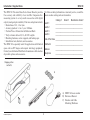
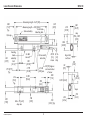
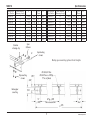
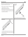
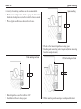
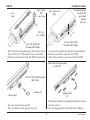
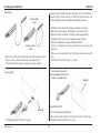
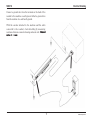
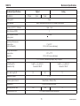
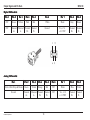
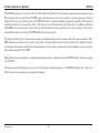
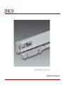
SENC 50
REFERENCE MANUAL
Acu-Rite Companies Inc.
SENC 50
Table of Contents
Page
Introduction / Supplied items ............................................... 2
Page
Checking the Installation .................................................... 10
Electrical Shielding .............................................................. 11
Troubleshooting ................................................................... 12
Key Points / Tolerances ......................................................... 3
Linear Encoder Dimensions .................................................. 4
Spar Dimensions .................................................................... 5
Mechanical Specifications ................................................... 13
Output Signals and Pin-Outs .............................................. 14
Electrical Specifications ...................................................... 15
Mounting Requirements ........................................................ 6
Typical Mounting ................................................................... 7
Encoder Installation Procedure ............................................ 8
The Acu-Rite Companies Inc.
Hassle Free Warranty & Service ........................................ 16
Adjustable front or
rear mount
Spar
Front mount
bracket
Front mount
bracket
Bottom mount
bracket
Base mount
• Installation brackets and kits are available.
• Your Authorized Distributor can assist you in selecting
brackets and tools for your installation.
1
Acu-Rite Companies Inc.
Introduction / Supplied Items
SENC 50
For future ordering information or warranty service, record the
linear encoder catalog and serial numbers.
The SENC 50 Precision Glass Scale Linear Encoder provides
the accuracy and reliability of an Acu-Rite Companies Inc.
measuring system in a very small cross-section with digital
output (analog output available). Features and options include:
• Resolutions of 0.5, 1.0 or 5µm.
• Accuracy grades of ± 3 or ± 5 µm / 1000mm.
• Position Trac or 50mm interval Reference Mark.
• Vinyl or Armor cables of 5, 13, & 19 ft. lengths.
• Mounting fasteners, center supports, and backup spar.
• Installation tools, brackets, and accessories.
The SENC 50 is especially useful for applications with limited
space such as X/Y stages and compact metrology equipment.
Contact your Authorized Distributor for assistance with selection
of product options and accessories.
Catalog #
Serial #
Manufacture Code #
_____________________________________
_____________________________________
_____________________________________
_____________________________________
Axis # 1:
Axis # 2:
Axis # 3:
Axis # 4:
Date of Purchase _____________________________________
Distributor:
_____________________________________
Address:
Telephone:
_____________________________________
_____________________________________
Shipping carton
contents
B
A
A) SENC 50 linear encoder
B) Reference Manual
C) Encoder and Cable
Mounting Hardware
C
Acu-Rite Companies Inc.
2
SENC 50
Key Points / Tolerances
// .005 A
-A- = Machine travel
Center support surface
required
Reading head
assembly
Gap
B
.059 ±.005”
[1.50]
Scale assembly
// .005 A
Equal
Equal
// .005 A
• Tolerances of .005” TIR apply to all mounting dimensions.
• Center support surface required for all measuring
lengths when not using a back up spar.
Shipping bracket removal clearance
1.00
// .005 B
// .005 A
Use this information to plan your Linear Encoder installation.
• Understand your mounting requirements.
• Follow kit instructions when using an Acu-Rite Companies
Inc. bracket kit.
• Mount encoders close to ways to insure system accuracy.
• Mount with lip seals down and away from the work area.
• Brackets should be short and rigid.
• Surfaces must be in good condition, clean and free of
dirt and paint.
Do not remove shipping brackets until instructed.
•
• Shipping bracket spacers can be used to insure .059” gap.
• Mount from either side to obtain desired cable exit direction.
Total head travel
1.00
.26 [6.6]
Min.
Slide brackets away
from the reading head
.037 [.9]
Min.
Measuring length + 1”
[25.4] over travel
• Allow clearance for shipping bracket removal.
• Limit equipment travel to less than measuring length.
3
Acu-Rite Companies Inc.
Linear Encoder Dimensions
SENC 50
Measuring length + 4.65 [118]
.280
[7.11]
Typ.
Measuring length + 4.09 [103.9]
Scale case
Scale assembly
Mounting hole
End cap
.335
[8.51]
.670
[17.00]
1.182
[30.00]
.140
[3.55]
Reading
head
assembly
.463
[11.76]
for M4
Hex nut
1.85
[47.00]
2.775
[70.50]
.175 [4.57]
Typ.
.213
[5.41]
Typ.
2.350
[59.69]
Strain relief
and cable
Ø .30
[7.6]
Armor
2.0 [50] Approx.
Ø .160
min bend radius
[4.00] min.
of armor
.280
[7.11]
.150
[3.81]
Ø .16
[4.1]
Vinyl
.482
[12.25]
.Gap
.059 ± .005
[1.50]
Align both
surfaces
.02
[0.5]
1.352 [34.34]
.170
[4.32]
.840
[21.34]
Spar
.295
[7.50]
Acu-Rite Companies Inc.
M3 x .25 [6.31]
deep min.
.138
[3.50]
.159
[4.04] Typ.
4
.652
[16.56]
.170
[4.32]
SENC 50
Spar Dimensions
Backup spar
Part Number
680803-01
680803-02
680803-03
680803-04
680803-05
680803-06
680803-07
680803-08
680803-09
Linear Encoder
Measuring Length
1
2
3
4
5
6
7
8
9
Encoder
retaining clip
L
A
5.650
6.650
7.650
8.650
9.650
10.650
11.650
12.650
13.650
.825
.825
1.325
1.825
2.325
2.825
3.325
3.825
1.825
X No.
Places
2
2
2
2
2
2
2
2
3
B
Backup spar
Part Number
680803-10
680803-11
680803-12
680803-13
680803-14
680803-15
680803-16
680803-18
680803-20
4.000
5.000
5.000
5.000
5.000
5.000
5.000
5.000
5.000
Linear Encoder
Measuring Length
10
11
12
13
14
15
16
18
20
L
A
14.650
15.650
16.650
17.650
18.650
19.650
20.650
22.650
24.650
2.325
2.825
3.325
3.825
1.825
2.325
2.825
1.325
2.325
X No.
Places
3
3
3
3
4
4
4
3
3
B
5.000
5.000
5.000
5.000
5.000
5.000
5.000
10.000
10.000
Spar
fastener
Spar leveling
screws
Backup spar mounting optional for all lengths
Clip mounting
screws
Backup spar
mounting
.075
.330
Ø .196 Drill thru
Ø .344 C’bore x .100 Dp.
“X” no. of places
.510
“A”
± .005
B Typ. ±.005
Non accumulative
L
5
±.015
“A”
Ref.
Acu-Rite Companies Inc.
Mounting Requirements
SENC 50
Mounting options can be adapted to machine mounting surfaces
using spacers, standoffs, and leveling screws.
Center support
assembly
• Measuring length and mechanical configuration of your
equipment determines your options.
• Length related mounting options shown.
• When a backup spar is used, mount the backup spar following
the same procedure as required for mounting without a backup
spar, using the same tolerances.
• 8” and larger: End mounting holes with center support.
End mounting holes
• 7” and smaller: End mounting holes with encoder mounted to
a continuous flat surface, or with center surface on same plane
as end mounting surfaces.
Acu-Rite Companies Inc.
6
SENC 50
Typical mounting
Spar mounting
A variety of mounting conditions can be accommodated.
• Mechanical configuration of the equipment determines
brackets and adapters required to install the linear encoder.
• Three typical conditions are shown for reference.
// .030
• Flush or offset mounting surfaces using a spar.
• Reading head mounting bracket required (bottom mounting
bracket example shown).
Flush mounting surfaces
Offset mounting surfaces
// .030
// .005
• Mounting surfaces are flush within .005”.
• Installation without a backup spar.
• Offset mounting surfaces using a reading head bracket.
7
Acu-Rite Companies Inc.
Encoder Installation Procedure
SENC 50
These steps apply to all mounting conditions. Although this
may not pictorially represent your application, your installation
procedure should follow these steps.
Center mounting axis
Acu-Rite Companies Inc. B racket Kit instructions
supercede this section.
• General steps for small X & Y stage.
• Adjust drill depths and fastener lengths as required.
• Contact your Authorized Distributor if assistance is required.
•
CL
Mark center of axis
• Center the axis.
• Mark the axis for easy return to center.
Scale case
CL
Underside of end caps to be
flush with parting line of
upper slide.
Keep head and
scale case
surfaces flush
Align top of scale case to
within .015” of axis travel
Scale case
Shipping
brackets (2)
Reading head
Strain relief
and
cable assembly
End cap
• Center the reading head on the scale case by sliding the head
and shipping brackets together along the scale case.
Acu-Rite Companies Inc.
Mark end mounting
hole location
• Locate the linear encoder along the axis parting line.
• Mark location of one end mounting hole in the scale case.
8
SENC 50
Axis
travel
Installation Procedure
Align to within
.005”
to axis travel
Use shipping brackets
to maintain .059
gap between
head and
scale case.
Drill / tap for 6-32
(M3).
Drill / tap
for 6-32 (M3).
CL
6-32 x 3/4” SHCS & M3
flat washer (M3 x 20mm)
6-32 x 3/4” SHCS & M3
flat washer (M3 x 20mm)
• Drill / tap the first end mounting hole / Attach the scale case.
• Align to within .005” TIR. and drill / tap second end hole.
• Attach scale case & align to within .005” TIR. of the axis travel.
• Center the axis and mark the reading head mounting holes.
• Move the axis and drill / tap holes for 6-32 (M3).
• Attach head and align to scale case to within .005” TIR.
Slide bracket from reading head
and twist 45°
6-32 x 3/4” SHCS & M3 flat washer
(M3 x 20mm)
Center support
Retaining clip
Shipping bracket
(2)
• Slide shipping brackets from reading head and twist to remove
from the scale case.
• Save the shipping brackets with the Reference Manual.
• Use center supports when provided.
• Place at uniform intervals along the scale case.
9
Acu-Rite Companies Inc.
Checking the Installation
SENC 50
Connecting
These steps will confirm proper operation of your installation.
Counting tests check channel A and B output function and
Reference Mark tests check Reference Mark operation.
Provide slack
loops
•
•
•
•
•
•
Configure the readout for proper counting resolution.
Move axis and compare the display to the movement.
Repeat test for mechanical integrity and repeatability.
Configure the readout for sensing reference mark.
Move the reading head approximately 20mm.
Locate an indicator on scale end and zero out axis and
indicator.
• Move axis out and back over full travel and return to dial
zero.
• Electronics should read zero ± 1 count.
Secure excess
cable
• Route the cables with slack loops to allow for axis motion.
• Secure excess cable by fastening with clips or ties.
• Attach the linear encoder connectors to the readout.
Place indicator at end of
moving component (scale case
shown, or reading head).
Counting Test
Readout
Repeatability Test
Readout
• Zero the display and indicator.
• Move axis to the end of it’s travel, then return to dial zero.
• Readout should read zero ± 1 count.
• Check function of the linear encoder.
Acu-Rite Companies Inc.
10
SENC 50
Electrical Shielding
Connect a ground wire from the terminal on the back of the
readout to the machine or earth ground. Attach a ground wire
from the machine to a solid earth ground.
With the encoder attached to the machine and the cable
connected to the readout, check shielding by measuring
resistance between connector housing and scale unit. Desired
value: 1 Ω max.
11
Acu-Rite Companies Inc.
Trouble Shooting
SENC 50
• Insure that the linear encoder connectors are correctly seated.
• Swap linear encoder cables at the readout to see if the problem
is still shown in the same display.
• If the problem remains in the same display, the readout is in
error.
• If the problem follows the connection change, the linear
encoder may be in error.
• Follow this procedure for any intermittent problem
experienced.
with other machine structures through the length of the linear
encoder travel.
• Check for loose fasteners. If you find loose fasteners, first
confirm that the linear encoder is installed to the tolerances
specified and then retighten the fasteners as required.
• Confirm that the linear encoder is installed to the required
tolerances by checking the alignment tolerances specified on
Page 3 “Key Points”
Points”. If the installation does not meet the
tolerances, reinstall the linear encoder according to the
Installation
procedures in “Installation
Installation”.
• Perform a Repeatability Test as described on Page 10,
Checking Your Installation
“Checking
Installation”. If the linear encoder is
installed to the required tolerances, the bracketry and linear
encoder have been checked for interferences and loose
fasteners, and the linear encoder fails the repeatability test,
the linear encoder is likely at fault.
do to arrange for
If the readout is at fault, refer to “What
What to do”
the parts necessary to repair your system. If the linear encoders
appear to be the cause, perform the next step.
Do not attempt to repair the linear encoder. The units are only
serviceable by assembly replacement. Attempted repair can
permanently damage the unit and void the warranty.
Checking the Linear Encoders
What to do
If you experience difficulties with your installation, there are
methods to analyze the difficulty. Operating difficulties can be
caused by either the linear encoders or the readout.
Checking the readout
Follow the steps below to determine if your difficulties are
associated with the readout:
Linear encoder difficulties can be caused by improper
installation, loose or misaligned bracketry, or a damaged / failed
linear encoder.
If an Acu-Rite Companies Inc. linear encoder or readout is found
to be at fault, prior to removing the linear encoders or readout
contact your Authorized Distributor or OEM/OEI for repair
instructions.
Follow the steps below to determine the cause of your system
difficulties:
• Confirm that your bracketry and installation does not interfere
Acu-Rite Companies Inc.
12
SENC 50
Mechanical Specifications
Mechanical Specifications
Resolution
Digital
0.5µm
Analog
1µm
5µm
Grating pitch
20µm
Scale medium
Light transmission reflective off of chrome coated glass
Accuracy (@ 20° C) / 1000mm
± 3µm, ± 5µm
Max. slew speed (M/s)
1
Force required to move
reading head
< 0.5 (lbs)
Operating Environment
Temperature
Relative Humidity
0° to 50° C
20% to 95% (non-condensing)
Storage Environment
Temperature
Humidity
- 20° to 70° C
20% to 95% (non-condensing)
Weight
Connecting cable
armored or vinyl
Max. cable length (ft)
1.1 + 0.2 lbs/ft of measuring length [64g + 5.6g/in.]
Length = 5, 13, and 19 ft.
Connector: DE-9P
20
Length = 5, 13, and 19 ft.
Connector: DE-9P
26
Measuring lengths
75
1” - 20”
Reference pulse interval
50mm fixed or Position Trac
Repeatability
Within one resolution count
Operating current (ma)
Protection (IEC 529)
220
180
75
IP 53 when installed as per instruction
13
Acu-Rite Companies Inc.
Output Signals and Pin-Outs
SENC 50
Digital Differential
Pin 1
Pin 2
Pin 3
Pin 4
Pin 5
Pin 6
Pin 7
Pin 8
Pin 9
N/C
Green
Yellow
Pink
Red
White
Black
Gray
Brown
N/C
Channel
A+
Channel
A-
Ground
Vcc, + 5.1
± 0.1 VDC
Channel
R+
Channel
R-
Channel Channel
B+
B-
1
5
6
9
Analog Differential
Pin 1
Pin 2
Pin 3
Pin 4
Pin 5
Pin 6
Pin 7
Pin 8
Pin 9
White w/Grn Stripe & Brown
Green
Yellow
Orange
Red
N/C
Black
Blue
Violet
Ground
Channel
A+
Channel
B-
N/C
Vcc, + 5.0
± 0.1 VDC
Channel
R+
Channel
R-
Acu-Rite Companies Inc.
Channel Channel
AB+
14
SENC 50
Electrical Specifications
Parameter
Output Signals
Digital
Analog
IOH=(High level output current) = 20mA
VOH=(High level output voltage) >2.5Vdc
0°
1
0
Channel A- 1
0
360°
Channel A+
Channel R+
Channel R90°
1
Channel B
0
1
Channel A
Incremental signals
Signal levels
Square-wave voltage signals.
Channels A and B, in 90°
quadrature relationship
TTL-level
Reference Mark signals
Square-wave signal
Signal level
TTL-level
360°
IA, B:7-16 µApp
or
1.0 Vpp
0
1
1 Count
(Phased)
0
1
Channel B0
IOL=(Low level output current) = -20mA
VOL=(Low level output voltage) < 0.6Vdc
Channel B+
0° 90°
IR:2-8 µApp
or
1.2 Vpp
Channel R
Similar phasing, but differential
sinusoidal current or 1 volt peak to peak output
7-16µApp or 1.0 Vpp
w/1 K Ohm load
Differential current or 1 volt peak to peak output
2-8µApp or 1.2 Vpp
w/100 K Ohm load
Power Supply
5.1 ± 0.1 VDC @ 220 mA max.
15
5.0 ± 0.1VDC @ 75 mA max.
Acu-Rite Companies Inc.
Acu-Rite Companies Inc. Warranty
SENC 50
ACU-RITE Companies, Inc. is proud to offer the 3-Year Hassle-Free Warranty for all readout systems, and precision glass scales.
This warranty will cover all of the ACU-RITE repair and replacement costs for any readout or precision glass scale returned
during the three (3) year warranty period. ACU-RITE will repair or replace the damaged components regardless of the product’s
condition absolutely free, no questions asked. This warranty covers both materials, and factory labor. In addition, authorized
ACU-RITE service representatives will provide service labor (field service) for a period of one (1) year at no charge. Notice of the
claimed defect must be received by ACU-RITE within the warranty period.
This warranty applies only to products and accessories installed and operated in accordance with this reference manual. ACURITE shall have no obligation, with respect to any defect, or other condition caused in whole or part by the customer’s incorrect
use, improper maintenance modification of the equipment, or by the repair, or maintenance of the product by any person except
those deemed qualified by ACU-RITE.
Responsibility for loss of operation, or diminished performance due to conditions beyond ACU-RITE’s control cannot be accepted
by ACU-RITE.
The foregoing warranty obligations are in lieu of all expressed or implied warranties. ACU-RITE Companies, Inc. shall not be
liable under any circumstances for consequential damages.
Acu-Rite Companies Inc.
16
Acu-Rite Companies Inc.
IS AN
ISO 9001
CERTIFIED
MANUF
ACTURER
MANUFACTURER
Acu-Rite Companies Inc.
One Precision Way • Jamestown, NY 14701
516353-21 Ve01
8/2009