1
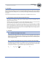
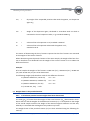
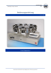
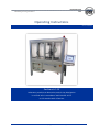
Müncheberg • Freising • Homécourt Operating Instructions Version: 25/03/13 Sedimat 4-12 Laboratory machine to determine particle size distribution in mineral soils in accordance with DIN ISO 11277 on 12 samples with 4 fractions Umwelt-Geräte-Technik GmbH • Email: [email protected] • Web: www.ugt-online.de Müncheberg • Freising • Homécourt Table of contents 1. Principles for determining the particle size distribution ........................................................................ 3 2. Accessories.......................................................................................................................................... 4 3. Additional equipment required for complete fine soil analysis .............................................................. 5 4. Preparation and installation of the soil samples, filling the rinsing baths ............................................... 6 4.1. Preparation of the samples ............................................................................................................6 4.1.1. Removal of organic substance from the divided samples ........................................................6 4.1.2. Removal of soluble salts ...........................................................................................................7 4.2. Dispersion.......................................................................................................................................7 4.3. Wet sieving.....................................................................................................................................7 5. Installation of the soil samples, filling the rinsing baths ........................................................................ 8 6. Switching on the SEDIMAT ................................................................................................................... 9 7. End of program.................................................................................................................................. 12 8. Settings ............................................................................................................................................. 12 8.1. Temperature control of the sample tempering bath...................................................................12 8.1.1. Thermostat..............................................................................................................................12 8.1.2. Control comparator ................................................................................................................12 8.2. Dispensing unit with pipette ........................................................................................................13 8.2.1. Function settings .....................................................................................................................13 8.2.2. Height comparison of the pipette...........................................................................................13 8.2.3. Correction of the pipetted volume .........................................................................................14 8.3. Agitator unit .................................................................................................................................14 9. Test analysis ...................................................................................................................................... 15 9.1. Determining the volume of the dispersion agent (blind value) ...................................................15 9.2. Calculation....................................................................................................................................15 9.2.1. Calculation of the weights of sieve residue ............................................................................15 9.2.2. Calculation of the weight of the slurry fractions, converted to the sample weight ...............15 9.3. Weight shares in the particle fractions ........................................................................................16 9.3.1. When all relevant particle fraction weights have been determined ......................................16 9.3.2. If only one or only a part of the particle fractions is to be determined .................................17 9.4. Standard deviation .......................................................................................................................17 10.Frequent causes of analysis faults ...................................................................................................... 17 11.Technical data ................................................................................................................................... 18 12.Service and maintenance ................................................................................................................... 18 Umwelt-Geräte-Technik GmbH • Email: [email protected] • Web: www.ugt-online.de Page 2 of 18 Müncheberg • Freising • Homécourt 1. Principles for determining the particle size distribution The determination of mass fractions of mineral particle size fractions in mineral soils (organic substance < 10%) is used for the precise determination of the soil type. Knowledge of the composition of the particle size fractions furthermore permits estimates to be made about the storage and exchange capacity for water, nutrients or pollutants as well as the aeration, shrinkage behaviour or stability of the soil. These parameters are decisive, for example, for the water balance of soil, for suitable types of use, for agricultural suitability, for workability and for the ability to use vehicles on the land. Where there is no information to the contrary, the soil type refers to the fine soil (equivalent particle diameter < 2 mm). The ratio of coarse soil is merely specified as added information. In the case of a < 75 % ratio of coarse soil to total soil, the fraction of coarse soil is specified instead of the soil type. The fine soil is divided into the soil types of sand, silt and clay, which can be represented in the particle triangle. Loam contains all three fractions in similarly sized proportions. S = sand U = silt T = clay L = loam s = sandy u = silty t = clayey l = loamy Example: Lts = Clayey sandy loam With the following composition: 123% silt 39% sand 37 % clay Figure 1: Simplified respresentation of the particle triange to illustrate the principle Every soil can be demonstrated according to its composition as a point in the particle triangle. The coloured areas indicate the soil type the soil belongs to according to the main fraction. If a fraction dominates less strongly, the next strongest fraction is specified by the addition of sandy, silt, clayey or loamy and represented by additional small letters. Umwelt-Geräte-Technik GmbH • Email: [email protected] • Web: www.ugt-online.de Page 3 of 18 Müncheberg • Freising • Homécourt In English-speaking areas not only the nomenclature differs, but also the fraction limits and the determination guidelines. In Germany soil determination takes place using sieve and sedimentation analysis in accordance with DIN ISO 11277 and the soil type is established in line with the soil science mapping guidelines in DIN 4220. In English-speaking areas, the common and customary international practice uses the US soil taxonomy and testing in 2 fractions according to the ASTM. Figure 2: Comparison of the representation of the soil types of fine soil in accordance with DIN 4220 (left) and US soil taxonomy (right) The particle size composition of soil can be determined in the laboratory using combined sieve and sedimentation analysis. The Sedimat 4-12 automates the conducting of the sedimentation analysis for four fractions on up to 12 samples simultaneously, depending on the setting according to both DIN ISO 11277 and ASTM. 2. Accessories 12 1000ml measuring cylinders, high shape, hexagonal base, height 465mm 48 30ml, 50mm A 4 racks each for 12 weighing bottles weighing bottles Umwelt-Geräte-Technik GmbH • Email: [email protected] • Web: www.ugt-online.de Page 4 of 18 Müncheberg • Freising • Homécourt 3. Additional equipment required for complete fine soil analysis Laboratory technology Description Sample divider Laboratory drying cabinet Overhead shaker Sieve mesh size 2 mm Sieve machine with the required sieves of 0.63 mm, 0.2 mm and 0.063 mm mesh size plus a set of reference sieves Micro scales ±0.01 g Analysis scales ±0.0001 g Centrifuge bottles, wide-necked with flat base, made from polypropylene polymer (PP polymer) volume = 500 ml, thermally stable up to 110 °C Centrifuge, suitable to accommodate the centrifuge bottles Water bath Device to measure the electrical conductivity with connected conductivity cell Exsiccator Needed for: General sample preparation General sample preparation; test evaluation General sample preparation; removal of soluble salts General sample preparation General sample preparation General sample preparation; test evaluation General sample preparation; test evaluation Removal of organic substance Removal of organic substance Removal of organic substance Determination of the necessity to remove soluble salts Test evaluation Reagents Description Needed for: Removal of organic substance Hydrogen peroxide stock solution Hydrogen peroxide with water in the ratio 1 + 1, where necessarily diluted to 1 + 2 (V + V) 2-Octanol Removal of organic substance Sodium diphosphate, c(Na4P2O7) = 0.1 Sample preparation (as dispersing agent) mol/l 26.6 g sodium diphosphate with water dissolved to 1 l. The solution can be kept without special storage conditions for approx. 1 year. Umwelt-Geräte-Technik GmbH • Email: [email protected] • Web: www.ugt-online.de Page 5 of 18 Müncheberg • Freising • Homécourt 4. Preparation and installation of the soil samples, filling the rinsing baths 4.1. Preparation of the samples By way of preparation for the test, the soil sample to be examined is dried in the open or in a laboratory drying cabinet at a maximum 40°C and where necessary gently mechanically crushed to produce coarse particles. The entire soil sample is then pressed through a sieve with a mesh size of 2 mm to separate the coarse soil from the fine soil. After this a soil sample should still contain at least 100 g of fine soil. Transfer all of the fine soil to a sample divider and divide the sample mass until the mass of divided samples equals approx. 10 g. At least three parallel divided samples must be generated from one soil sample to produce a meaningful examination. Where possible the maximum number of 13 samples (12 test samples + 1 sample with determination of the dry mass ratio) should be made use of for the analysis with the Sedimat in order to guarantee the maximum significance and efficacy. The dry mass ratio is determined on one of the divided samples. This cannot be used for the further test procedure. The other parallel samples are weighed on the micro scales and the dry mass is calculated on the basis of the ratio of dry mass determined. Depending on the composition of the soil sample, other preparatory steps may be required. If the soil contains more than 2 % organic substance, it should be destroyed. In the case of soluble salts with a concentration of more than 0.5 %, their removal is recommended. 4.1.1. Removal of organic substance from the divided samples Place the sample in a centrifuge bottle and add 100 ml hydrogen peroxide stock solution in batches. In the process observe the reaction and allow strong reactions to subside before adding more. Slightly shake the bottle to mix the soil and solution, cover with a watch glass (do not seal tight!) and leave to stand overnight (for around 14 hours) at room temperature. Then place the centrifuge bottle in the water bath and heat to 90°C until the bubble formation resulting from the breaking down of the hydrogen peroxide has stopped and the soil appears to be free from humus (no longer has a dark colour). However the treatment should be aborted 24 h at the latest after commencing the addition of hydrogen peroxide (including overnight break). Observe the sample during heating. It must not dry out and soil must not dry on the side of the vessel. Prevent the latter by frequent rinsing with water. Strong foam formation should be prevented by adding drops of 2-Octanol. No soil may be lost with the foam. Then add water to the soil suspension to produce a final volume of from 150 to 250 ml. Place the centrifuge bottles in the centrifuge and spin for 15 to 20 minutes at 3,000 g. Decant the supernatant and wash the residue with water after thorough stirring. Repeat the process until the supernatant is largely colourless. Then determine the electrical conductivity (EC) of the supernatant solution using the measuring device and conductivity cell. If it is greater than 40 mS/m, the soluble salts should be removed before sedimentation analysis in the Sedimat 4-12. To do this, decant the supernatant and proceed according to 4.1.2. If the electrical conductivity is less than 40 mS/m, decant the supernatant and add the sediment without drying to the other pretreatment (from 4.2). Umwelt-Geräte-Technik GmbH • Email: [email protected] • Web: www.ugt-online.de Page 6 of 18 Müncheberg • Freising • Homécourt 4.1.2. Removal of soluble salts Soluble salts can interfere with dispersion and sedimentation of the soil particles. If they are present in a concentration of more than 0.5%, determined during measurement of the electrical conductivity (> 40 mS/m), their removal is recommended. To do this, add 200 ml water and the soil sample obtained by division (4.1) and where applicable treated according to 4.1.1 to the centrifuge bottle and shake upside down. Spin the suspension until the supernatant solution is clear. Determine the electrical conductivity of this solution with the measuring device. If it is below 40 mS/m, it contains only insignificant quantities of soluble salts and the treatment should be ended. If the electrical conductivity of the supernatant is above 40 mS/m, it should be decanted and the washing process repeated until an EC value of < 40 mS/m is present. After decanting the supernatant add the residue without drying to the other pretreatment in accordance with 4.2. 4.2. Dispersion Add 25 ml sodium diphosphate solution with the pipette to the pretreated and divided sample. Thoroughly moisten the soil sample by strong circular shaking movements and allow to stand overnight. The following morning add approx. 200 ml and shake the sample in an overhead shaker for 6 hours. 4.3. Wet sieving The analysis with the Sedimat 4-12 is only conducted for fine soil particles that are smaller than 0.063 mm. The larger fractions are separated and determined by wet sieving. To do this, weigh the sieves to an accuracy of 0.01 g and then insert in the sieving machine. For the wet sieving, deionised water is connected to the sieve machine. The sieve program should where possible be selected so that the fractions are precisely separated but that no more than 765 ml of water is used. Place the suspension from the centrifuge bottle on the top sieve (mesh size = 0.63 mm). Start the sieving process and collect the sieved fraction. End sieving when the sieved fraction through the bottom sieve (mesh size = 0.063 mm) is clear. If this state is not achieved with the specified water consumption, sieving should continue. The sieved fraction that occurs here is collected in a second vessel. Then the suspensions from both vessels should be mixed together and transferred to a measuring cylinder on the Sedimat 4-12. Excess water must be evaporated here beforehand. The volume of suspension and rinsing water should be precisely 1,000 ml. In the case of a suspension volume below 970 ml, top the measuring cylinder up with water. Attention! Samples with a fill height below 970 ml before removal of the first fraction will be left out by the machine! Dry the sieves with the sieve residue in the drying cabinet at 105 °C; then weight to an accuracy of 0.01 g. Alternatively transfer the sieve residues to weighing dishes, dry in the drying cabinet at 105°C until dried to constant mass and then weigh. Umwelt-Geräte-Technik GmbH • Email: [email protected] • Web: www.ugt-online.de Page 7 of 18 Müncheberg • Freising • Homécourt 5. Installation of the soil samples, filling the rinsing baths When the power supply is switched on the Sedimat starts heating the water bath to the set temperature. For conducting a test in accordance with DIN ISO 11277 this is 25°C. Bring the fill level of the tempering bath at least to the height of the 1000 ml mark on the measuring cylinder. The min. and max. marking on the side of the bath refer to a safe function of the thermostats. It should be fallen short of or exceeded. Check whether the rinsing vessels are filled up to the marked fill level of 1000 ml with sodium diphosphate stock solution and top up if necessary. Fill the sponge holder with water. Place the measuring cylinders from 4.3 filled with 1000 ml suspension on the numbered positions in the water bath of the Sedimat 4-12. If not all 12 positions are required, the measuring cylinders must be deployed consecutively without gaps according to the numbering, starting with position 1. Attention! Samples with a fill height below 970 ml before removal of the first fraction will be left out by the machine!! The time from filling the first cylinder to positioning the last (twelfth) cylinder should not last longer than four hours. Arrange the cleaned weighing bottles, pre-weighed to an accuracy of 0.1 mg, for fractions F1 to F4 in the racks according to the installed soil samples. Racks for weighing bottles F1 F3 Test cylinder Sponge F2 F4 Rinse water P1 1 2 3 4 S 5 6 7 8 P2 9 10 11 12 Sitirrer cleaning Pipette cleaning Fig.1: Example for the arrangement of the measuring cylinders and the weighing bottles for six samples Before the start of the test, wipe the surface sensor with a damp cloth and check the correct fill level of 1000 ml distilled water in the cylinders for cleaning and rinsing water (marked in blue in Fig. 1). In particular this refers to cylinder P1 for rinsing the pipette, because water is actively removed here over the course of the test. Then start the Sedimat according to Chapter “6. Switching on the SEDIMAT”. Umwelt-Geräte-Technik GmbH • Email: [email protected] • Web: www.ugt-online.de Page 8 of 18 Müncheberg • Freising • Homécourt 6. Switching on the SEDIMAT To prevent prohibited sedimentation of the set soil samples, the samples should be shaken again or a stirring program started after standing for longer than 4 hours before starting the test. Attention! Before switching the system on, all obstacles (e.g. container covers) should be removed from the work area! Check again that all containers are positioned exactly and that the fill level in the tempering bath is correct! First switch on the main switch [1] in the control cabinet and then the mains switch on the machine controller [2]. Then press the “Power” start button [3]. Fig.2: View of the control cabinet 1 3 2 Pressing the start button on the system computer starts the operating system and the control software. The machine controller software ProNC appears on the user interface: Fig.3: View of the der ProNC controller sofware If the ProNC machine controller software does not start automatically, the program can also be started manually using the path “Start/Programme/CNCWorkbench/ProNC starten“. Check whether the thermostat (see 8.1.1. for settings) is switched on. Turning on the voltage supply of the peripheral devices takes place on the system. The mains switch on the thermostat can therefore always remain switched on. Check whether pipette is switched to external controller (COM) (see 8.2.1.), Check whether there is 3 – 4 ml water above the pipette plunger (see 8.2.2), Check the fill level of the rinse tank Check whether the sponge is moist Click on “yes” with the mouse for reference run Call up program by clicking on “run” button with the mouse In the following menu select and open the file “DIN11277.CNC“. Umwelt-Geräte-Technik GmbH • Email: [email protected] • Web: www.ugt-online.de Page 9 of 18 Müncheberg • Freising • Homécourt Program selection - Dialog Select the required program run in the program selection reader by entering a program number. 1: Fraction 1 (DIN) 2: Fraction 2 (DIN) 3: Fraction 3 (DIN) 4: Fraction 4 (DIN) The following variants are possible by entering numerical strings: 1234 – Fract. 1 to 4 4123 – Fr. 4 u. 1 to 3 123 – Fract. 1 to 3 234 – Fract. 2 to 4 12 – Fract. 1 to 2 23 – Fract. 2 to 3 34 – Fract. 3 to 4 14 – Fract. 1 and 4 1 – Fract. 1 2 – Fract. 2 3 – Fract. 3 4 – Fract. 4 8: Intermediate agitation Extra agitation program to stir samples which have stood for some time. 10: Pipette height adjustment The pipette is positioned over the front rinse tank and moves along the water surface with the sensor. In this position, the pipette height is adjusted such that the pipette tip is directly on the water surface (see 8.2.2.). 110: Additional program for determining the volume of the pipette Using this program, 10ml water is taken from the rinse cylinder P and placed in the weighing bottle of fraction 1. The actual pipetted volume can be checked by weighing (see 8.2.3.). “First sample” entry is at position number: ? “Last sample” entry is at position number: ? Inquiry as to whether the standard options are to remain unaltered. Here, only click on <No> if you wish to alter the standard value for the sample warming time (30 min) or in exceptional cases if work is to be performed without the surface sensor (fixed depth). Umwelt-Geräte-Technik GmbH • Email: [email protected] • Web: www.ugt-online.de Page 10 of 18 Müncheberg • Freising • Homécourt This window only appears if you acknowledge the confirmation of the standard options with <No>! Entry of the waiting time (in minutes) after reaching the setpoint temperature in the sample bath for reliable warming of the samples. The standard value is 30 minutes. If you click on <Cancel> it is maintained. If your samples have already been in the tempered water bath for long enough, you can enter 0 (minutes) here. The system will then start sampling without a waiting period. However, you call also increase the waiting period. The system initialises agitator and pipette and conducts a cleaning of the pipette. Sampling commences automatically once the set point temperature in the sample tempering bath has been reached and the set heating time has been kept within the range of +/- 0.4 K. Attention! Check the freedom of movement of the axes and tools before starting the program. All selected sample positions and the rinsing baths must be assigned and may not be limited. There should be no activity in the movement area of the axes during the program. Close the protective doors during program run. The program run can be stopped using the emergency stop button. The emergency stop button must first be unlocked by turning it to the right after actuation for restart. Then, the control program must be stopped by a mouse click on the cancel button “ProNC”. The procedure can be restarted after Point 6. in Remark! You have the possibility (e.g. after stoppage) to start a program run at any sample. Any following fraction is basically continued with the first sample. Example: You enter 234 as program selection for 2nd to 4th fraction. You enter 8 for example as first sample. You enter 11 for example as last sample because you have only fitted eleven samples. The Sedimat will then take the samples 8 to 11 of the 2nd fraction, then the samples 1 to 11 of the 3rd fraction and then the samples 1 to 11 of the 4th fraction. Umwelt-Geräte-Technik GmbH • Email: [email protected] • Web: www.ugt-online.de Page 11 of 18 Müncheberg • Freising • Homécourt 7. End of program At the end of program, the message: “Procedure finished” appears on the monitor. Pipette and agitator are parked in home position. After confirming by mouse click on “Ok”, the control program asks whether you wish to start a further program run or stop. After stopping, close the control interface “ProNC”, shut down the operating system and then switch the main switch off. The racks with the pipetted fractions of the tested samples can now be taken and placed in the drying cabinet. 8. Settings The settings described in the following are necessary only under certain circumstances. 8.1. Temperature control of the sample tempering bath 8.1.1. Thermostat The suspended thermostat regulates the set bath temperature with high constancy and ensures optimum bath circulation. On delivering the laboratory machine, the setpoint temperature had a default of 25 °C. If a change of the settings is necessary, please derive the setting information from the supplied manufacturer’s description of the machine. The main switch of the device can always remain switched on and the system searches for the voltage supply. The installation of a cooling system is necessary for working in room temperatures above 25°C. 8.1.2. Control comparator The system monitors the bath temperature via the installed temperature control comparator. The comparator was set to the setpoint temperature (25 °C on delivery). After reaching the setpoint temperature, the software realises the set waiting time for the reliable heating of the samples. If there is a > 0.4 K deviation of the bath temperature from the setpoint value, the procedure is stopped by the software. This avoids a situation in which unnoticed temperature fluctuations falsify the results. After stopping the test as a result of temperature fluctuations, the test should be restarted completely. To prevent frequent test stops, the Sedimat should stand in room with a temperature which is as constant as possible. Umwelt-Geräte-Technik GmbH • Email: [email protected] • Web: www.ugt-online.de Page 12 of 18 Müncheberg • Freising • Homécourt 8.2. Dispensing unit with pipette 8.2.1. Function settings Please observe the information in the supplied instructions of the dispenser manufacturer. This applies in particular when replacing the lift unit (Tip). All settings such as initialisation, reference run, status check and fault monitoring of the automatic pipette are made software-controlled via the serial interface. It is necessary, however, to place the pipette manually over the keys for external control beforehand. This is a factory default and is displayed by the lettering “COM” in the bottom right hand corner of the display. If this is not the case, this setting should be restored. For this purpose, you must first keep the left key <Menu> pressed for around 3 s. If the display starts to flash, you must briefly press the left <Menu> key twice until “OFF” appears in the display. Now press once on the up or down arrow key (,) until “ON” can be read in the display. Complete the entry by pressing the right <Enter> key. The release of the external control is now shown in the bottom right hand corner of the display by “COM”. 8.2.2. Height comparison of the pipette Particularly after replacing the tip, it is necessary to correct the exact position of the pipette tip to the surface sensor. After starting the program, enter “10” in the program selection dialog for pipette height adjustment. The pipette is positioned over the rinse water in vessel P1 and travels over the water surface with the sensor. In this position, set the pipette height such that the pipette tip is directly above the water surface. Loosen the PG screwed connection at the top end of the pipette for this, adjust the pipette and then tighten the screw. If the height adjustment area of the pipette is not sufficient, you have the possibility to achieve the exact adjustment of the pipette tip by adjusting the height of the sensor. Umwelt-Geräte-Technik GmbH • Email: [email protected] • Web: www.ugt-online.de Page 13 of 18 Müncheberg • Freising • Homécourt Lift unit (Tip) PG screwed connection - loosen set pipette height tighten Attention! Please ensure that 3 – 4 ml dist. water is always above the pipette lift piston to minimise wear. 8.2.3. Correction of the pipetted volume The actual volume taken up can be checked with the “additional program for volume determination of the pipette”. After starting the program, enter “110” in the program selection dialog for “volume determination at the pipette”. In this program, 10ml water is taken from the rinse water cylinder P1 and placed in the weighing bottle of fraction 1. The actual pipetted volume can be determined by weighing. To correct to the setpoint value of 10ml, use the file P_Offset.txt. in the C:\ directory of the control computer. A correction value between –0.9ml ... 0.0ml ... +0.9ml can be entered in this file in 0.1ml steps using the editor. Attention! Please consider when entering the correction value that the decimal separator must be a point [.]. 8.3. Agitator unit All settings such as initialisation, status check and fault monitoring of the agitator unit are made software-controlled via the serial interface. The system switches in the voltage supply. Umwelt-Geräte-Technik GmbH • Email: [email protected] • Web: www.ugt-online.de Page 14 of 18 Müncheberg • Freising • Homécourt 9. Test analysis After the end of the program, the racks with the filled weighing bottles are taken from the Sedimat and dried in the drying cabinet at 105 °C. For simple handling, the weighing bottles can be placed in the drying cabinet in the complete rack. This also reduces the danger of confusing individual samples or fractions. Then allow the dried samples to cool down in the desiccator and weigh exactly to 0.1 mg. 9.1. Determining the volume of the dispersion agent (blind value) The weight of the dispersion agent must be known because it must be deducted from the weight of the pipette fractions. Assuming a very precise manufacture of the sodium diphosphate solution, the theoretical blind value of 0.0067g can be applied to a volume of 10 ml of the diluted solution. Alternatively, this value can be determined by adding 25 ml of the dispersion agent to a KÖHN cylinder and topping up to 1 000 ml with water. Mix the solution well and then allow to stand for 1 h. Take 10 ml at least three times and place it in the weighing bottles or jars (not in vessels made of aluminium), dry in the same way as the soil samples, weigh, form the average value of the weighed results and note these. 9.2. Calculation 9.2.1. Calculation of the weights of sieve residue To determine the weight of the sieve residue (mrfp) and the suspended particles taken up with the pipette incl. dispersion agent, the fractions (fi) of the sample (p), calculate the dry weights by forming the difference from the empty weight of the sieve or evaporating dishes and the weight after filling. 9.2.2. Calculation of the weight of the slurry fractions, converted to the sample weight The weight of the slurry fractions fi of a sample P (mfip) in g, from which the mB g air-dried material was weighed in, so that a suspension of VS ml is made and thereof VP ml was taken by the pipette for analysis is to be calculated using the following formula (1): mfip = (msfp - mdm) • VS VP [g] Umwelt-Geräte-Technik GmbH • Email: [email protected] • Web: www.ugt-online.de (1) Page 15 of 18 Müncheberg • Freising • Homécourt msfp = dry weight of the suspended particles taken with the pipette, incl. dispersion agent in g mdm = weight of the dispersion agent, calculated in accordance with 9.1 which is contained in the soil suspension taken, in g; standard is 00067 g VS = volume of the soil suspension in ml; standard is 1000 ml VP = volume of the soil suspension taken with the pipette in ml; standard is 10 ml The nature of determining the slurry fractions requires that the finer fractions are contained in the weights of the coarser fractions. When determining several particle fractions of the same sample, the weight of the finer fraction is therefore to be deducted from the weight of the coarser fraction so as to obtain the difference fraction. Example: Of a soil sample the weights of the fractions <0.063 mm (mf1), <0.020 mm (mf2), <0.006 mm (mf3) and <0.002 mm (mf4) are to be determined. The following weights (md) therefore result for the difference fractions: md (0.020 to 0.063 mm, coarse silt) = mf1 – mf2 md (0.006 to 0.020 mm, medium silt) = mf2 – mf3 md (0.002 to 0.006 mm, fine silt) = mf3 – mf4 md (< 0.002 mm, clay) = mf4 9.3. Weight shares in the particle fractions 9.3.1. If all relevant particle fraction weights have been determined The total (∑mkf) is formed from the weights of the sieve fractions (mrfp) determined in accordance with 9.2 and the weights of the difference fractions (md.). It corresponds to the weight of the overall sample used less the weight of the removed organic substance and the salts, whereby it is assumed that working does not produce any losses. The weight shares of the particle fractions (wkf) are then calculated using the following formula (2): Umwelt-Geräte-Technik GmbH • Email: [email protected] • Web: www.ugt-online.de Page 16 of 18 Müncheberg • Freising • Homécourt m x 100 m kf wkf = [%] (2) mx = weight of the respective sieve or difference fraction in g ∑mkf = total of particle fraction weights in g 9.3.2. If only one or only a part of the particle fractions is to be determined Calculate the weight share of the respective fraction in % from the weights of the sieve fractions (mrfp) determined in 9.2 and/or slurry fractions (msfp) and/or the difference fractions (md) using the following formula (3): wmt [%] mE wkf = mx • (3) mx = weight of the respective sieve or slurry or difference fraction in g mE = initial weight of the air-dried sample used in g wmt = dry weight share of the air-dried sample used in % 9.4. Standard deviation If the same sample is weighed and examined several times, the absolute difference between the parallels of average value for clay and fine silt may not exceed 0.25 g, and 0.50 g for medium and coarse silt. Exceptions are possible if the figures are exceeded if the samples have strong oxidation reactions or if several washes were necessary. 10. Frequent causes of analysis faults - Shaking during sedimentation Incomplete quantitative transfer to the sedimentation cylinder or the evaporating dishes Convection flows in the sedimentation cylinder caused by temperature layers, for example Uneven treatment of the residual quantity in the pipette or adhering drops Backflow of excess suspension Inaccurate initial weighing of the dispersion agent Forgetting the blind value during the calculation Umwelt-Geräte-Technik GmbH • Email: [email protected] • Web: www.ugt-online.de Page 17 of 18 Müncheberg • Freising • Homécourt 11. Technical data Device measurements Width : 1.69 m Width with side-assembled monitor : 1.76 – 2.08 m Depth : 0.86 m Height : 1.91 m : approx. 400 kg : CEE16, 16 A 3 N/PE AC 380 V / 50 Hz Total weight (ready for operation) Connection values Electrical connection Program run times with 12 samples and 30 minutes sample heating time to 25°C: DIN ISO 11277 ASTM Fraction 1 : ............... approx. 1.5 h approx. 1.5 h Fraction 2 : ............... approx. 2 h, 10 min approx. 8 h Fraction 3 : ............... approx. 2 h Fraction 4 : ............... approx. 8 h Fraction 1 to 4(2) : .. approx. 11 h 45 min approx. 9 h Sedimentation times realised by the program: DIN ISO 11277 ASTM Fraction 1 : ........... 49 s (Depth 20 cm) 80 s (Depth 20 cm) Fraction 2 : ........... 04:07 min (Depth 10 cm) 06:52:50 h (Depth 10 cm) Fraction 3 : ........... 45:52 min (Depth 10 cm) Fraction 4 : ........... 06:52:50 h (Depth 10 cm) 12. Service and maintenance So as to ensure reliable functioning of the device, the following service and cleaning intervals should be heeded. Once a week, cleaning of the agitation shaft, pipette and surface sensor with distilled water Once a year, service by the manufacturer - The agitation shaft and the pipette tip can be replaced during this service. Umwelt-Geräte-Technik GmbH • Email: [email protected] • Web: www.ugt-online.de Page 18 of 18