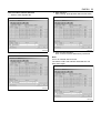
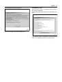
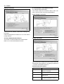
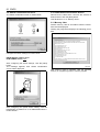
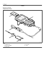
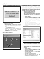
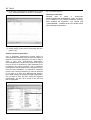
1
Trouble Diagnosis-Related Tool
Operating Instructions
Introduction
This Operating Instructions describes how to use the trouble diagnosis-related tools.
EMPSIII
EMPS
Tech2
Trouble Diagnostic Tool for Industrial Engine
Flash Tool
Trouble Diagnostic Tool
Function of each trouble diagnosis-related tool is as in the chart below.
Data display
KW communication
CAN communication
KW communication
ECM Reflash
Change Injector
QR Code
Actuator test
Use this manual sufficiently to perform service work properly and quickly.
Isuzu Motors Limited
Powertrain Business Dept.
EMPS
Operating Instructions
(Engine Module Programming System)
EMPSIII 1
Trouble Diagnostic Tools for Industrial Engine
Table of Contents
Trouble Diagnostic Tools (EMPSIII) for Industrial Engine........................................................................................... 3
Introduction .............................................................................................................................................................. 3
Cautions ................................................................................................................................................................... 3
EMPSIII Component Parts ....................................................................................................................................... 5
Precautions on EMPSIII Setup Procedure ............................................................................................................... 7
Before the EMPSIII (software) Setup ....................................................................................................................... 5
ECM (hardware) compatibility .................................................................................................................................. 9
ECM Variation ........................................................................................................................................................ 10
System Requirements for EMPSIII Software (Recommended) ............................................................................. 10
Available Display Language for EMPSIII Software ................................................................................................ 10
EMPSIII (software) Setup Procedure ..................................................................................................................... 11
Diagnosis Mode Operation Procedure ...................................................................................................................... 14
1. Connection ......................................................................................................................................................... 14
2. Startup................................................................................................................................................................ 15
3. Process Menu .................................................................................................................................................... 16
4. Trouble Diagnosis .............................................................................................................................................. 17
4.1 Diagnosis(DTC,Actuator,QR)........................................................................................................................ 17
4.2 QR Code Download ...................................................................................................................................... 26
5. HTML Manual Display........................................................................................................................................ 27
Reflash Mode Operation Procedure.......................................................................................................................... 29
1. Preparation......................................................................................................................................................... 29
1.1 Preparation ................................................................................................................................................... 29
1.2 EMPSIII Selector Connection ....................................................................................................................... 30
2. ECM Reflash ...................................................................................................................................................... 32
2.1 Startup .......................................................................................................................................................... 32
2.2 User Authentication Screen .......................................................................................................................... 35
2.3 Connection Confirmation Screen .................................................................................................................. 36
2.4 Switch Confirmation Screen.......................................................................................................................... 37
2.5 Current ECM Parts Number Confirmation Screen ........................................................................................ 38
2.6 New ECM Parts Number Search Screen ...................................................................................................... 38
2.7 New ECM Parts Number Search Result Confirmation Screen ..................................................................... 39
2.8 Reflashing ECM Parts Number Confirmation Screen ................................................................................... 39
2.9 Switch Confirmation Screen.......................................................................................................................... 40
2.10 READY LED Confirmation Screen .............................................................................................................. 40
2.11 Switch Confirmation Screen........................................................................................................................ 40
2.12 Reflashing Execution Confirmation Screen ................................................................................................ 41
2.13 Reflashing Result Confirmation Screen ...................................................................................................... 41
2.14 Final Result Confirmation Screen ............................................................................................................... 41
2.15 Switch Confirmation Screen........................................................................................................................ 42
2.16 Cable Removal Procedure Screen ............................................................................................................. 42
2.17 Memory Clear ............................................................................................................................................. 42
2.18 Reflash with Hardware Modification............................................................................................................ 43
2.19 Engine Replacement (Downward Compatible) ........................................................................................... 44
2.20 Compulsory Reflash.................................................................................................................................... 46
3. Injector Replacement ......................................................................................................................................... 50
3.1 Startup .......................................................................................................................................................... 50
3.2 User Authentication Screen .......................................................................................................................... 51
3.3 Connection Confirmation Screen .................................................................................................................. 51
3.4 Switch Confirmation Screen.......................................................................................................................... 51
3.5 Change Injector QR Code............................................................................................................................. 51
3.6 Injector QR Code Download ......................................................................................................................... 55
3.7 Change Result Confirmation Screen ............................................................................................................ 55
3.8 Switch Confirmation Screen.......................................................................................................................... 56
3.9 Cable Removal Procedure Screen ............................................................................................................... 56
3.10 Memory Clear ............................................................................................................................................. 56
2 EMPSIII
4. Replace ECM (Same Model) ............................................................................................................................. 57
4.1 Startup .......................................................................................................................................................... 57
4.2 User Authentication Screen .......................................................................................................................... 58
4.3 Connection Confirmation Screen .................................................................................................................. 58
4.4 Switch Confirmation Screen.......................................................................................................................... 59
4.5 Current ECM Parts Number Confirmation Screen ........................................................................................ 59
4.6 New ECM Parts Number Search Screen ...................................................................................................... 60
4.7 Switch Confirmation Screen.......................................................................................................................... 60
4.8 Connection Confirmation (After Connecting ECM) and Reflash Mode Selection ......................................... 61
4.9 ECM Replacement / Data Confirmation ........................................................................................................ 61
4.10 Reflashing ECM Parts Number Confirmation Screen ................................................................................. 62
4.11 Switch Confirmation Screen........................................................................................................................ 62
4.12 READY LED Confirmation Screen .............................................................................................................. 62
4.13 Switch Confirmation Screen........................................................................................................................ 63
4.14 Reflashing Execution Confirmation Screen................................................................................................. 63
4.15 Reflashing Result Confirmation Screen ...................................................................................................... 64
4.16 Engine Serial Number Confirm ................................................................................................................... 64
4.17 Injector QR Code Change Confirmation Screen ......................................................................................... 65
4.18 Result Confirmation Screen ........................................................................................................................ 65
4.19 Switch Confirmation Screen........................................................................................................................ 66
4.20 Cable Removal Procedure Screen.............................................................................................................. 66
4.21 Memory Clear.............................................................................................................................................. 66
5. Factory Setting ................................................................................................................................................... 67
5.1 Startup .......................................................................................................................................................... 67
5.2 User Authentication Screen .......................................................................................................................... 68
5.3 Connection Confirmation Screen .................................................................................................................. 68
5.4 Switch Confirmation Screen.......................................................................................................................... 68
5.5 Enter Engine Serial Number ......................................................................................................................... 68
5.6 Factory Setting Data Screen ......................................................................................................................... 69
5.7 Injector QR Code Download ......................................................................................................................... 69
5.8 Download Result Confirmation...................................................................................................................... 69
5.9 Switch Confirmation Screen.......................................................................................................................... 70
5.10 Cable Removal Procedure Screen.............................................................................................................. 70
5.11 Memory Clear.............................................................................................................................................. 70
6. ECM Information ................................................................................................................................................ 71
6.1 Startup .......................................................................................................................................................... 71
6.2 Switch Confirmation Screen.......................................................................................................................... 72
7. Option................................................................................................................................................................. 74
8. Error Code List ................................................................................................................................................... 76
EMPSIII 3
Trouble Diagnostic Tools (EMPSIII) for Industrial Engine
Introduction
Only the person with approval of the machine manufacturer or engine manufacturer can reflash ECM
using EMPSIII.
5. Do not have an impact on it by dropping. It causes
internal faults even no damage on appearance.
Cautions
For your safety, read the following cautions.
1. Always turn the POWER switch of EMPSIII selector to OFF before connecting/disconnecting the
cables. Before turning on the POWER switch of
EMPSIII selector, make sure that the cables are
connected securely.
EMPS1019
6. Avoid using and storing it in a place that it may
contact water or chemicals. When cleaning, use
cloth with mild detergent, not highly-volatile solvent
such as thinner, and wipe out using dry cloth.
EMPS1018
2. Do not disassemble the EMPSIII selector.
3. ECM can be reflashed up to around 100 times.
(The number of times varies depending on the
conditions of use.)
4. If the POWER lamp does not come on when turning the POWER switch ON with the power source
connected, check the fuse.
EMPS1020
4 EMPSIII
7. Avoid using and storing it in dusty area. Store it to
avoid dust on the connector etc. when you don’t
use.
9. Avoid using and storing it in a place with extreme
high or low temperature. Especially in summer, do
not leave it in the machine exposed to direct sunlight.
EMPS1021
8. Avoid using and storing it in a place with rapid
changes of temperature. If bringing it from cold
outside into warm indoor suddenly, dew condensation may occur resulting in malfunction or trouble.
EMPS1022
EMPS1023
EMPSIII 5
EMPSIII Component Parts
1
4
8
5
9
2
6
10
3
7
EMPS1051
Name
1. Selector (Hardware)
2. ECM cable
3. Battery cable
4. Datalink cable
5. 24V AC adapter
6.
7.
8.
9.
10.
USB cable
RS-232C cable
EMPS CD-ROM
12V AC adapter*
12V Power Assist Box*
* Optional item that is used when reflashing 12V ECM using the AC adapter.
Before the EMPSIII (software) Setup
Caution:
The ID (user name) and Password attached which are used to setup run EMPS, refer to the “Please Read
This First” on the separate sheet. (The ID and Password are attached to the bottom of the sheet.)
After EMPS setup is done, keep the paper for future reference.
6 EMPSIII
Before starting EMPSIII
EMPS performs data communication. Exit all other
communication software before starting the EMPS.
In addition, deactivate software and features that automatically communication regularly, such as Windows
Update. These may interfere with EMPS data communication.
Before starting operation, make sure that the ECM
PWR lamp is turned off.
If the lamp stays on, reconnect each cable and restart
the personal computer, then operate EMPS again. If
the error occurs again, EMPS might be faulty. Contact
the administrator.
EMPS1050
EMPSIII 7
Precautions on EMPSIII Setup Procedure
Step 2 [Installing a USB driver for EMPS]
Carry out the setup procedure following the
instructions.
Failure to complete setup properly, it might result
in a faulty performance of the EMPS program.
* Carry out the following procedure with the
“EMPSIII setup CD” inserted in the CD-ROM drive.
1. Connect your computer to EMPSIII as the figure
shown below, and turn on the EMPSIII power
switch.
2. Automatic installation wizard of the USB driver for
EMPS will start.
Carry out the following procedure with the “EMPSIII
setup CD” inserted in the CD-ROM drive.
1. Start the EMPSIII software setup. Refer to “Please
Read This First” on the separate sheet.
2. If a USB-Serial Converter driver, manufactured by
Arvel Corp, is installed on your computer, uninstall
it to prevent interfering with the EMPSIII USB
driver. (Refer to step 1.)
3. Carry out an EMPSIII hardware recognition. (Refer
to step 2.)
ECM
Diag
Terminating
Resistor
ON OFF
DC IN1 DC IN2
Engine Module Programming System
READY ECM PWR EMPS2
EMPS3
ECM PWR
ON
POWER
OFF
RS-232C
USB
FUSE 3A
POWER
ON OFF
Step 1 [Uninstalling an Arvel USB driver]
1. On the Windows [Start] menu, select [Settings],
then select [Control Panel]. [Control Panel] window
will appear. You can display the [Control Panel]
window also from the [My computer] icon on your
Windows desktop.
2. Click the [Add/Remove Programs] icon.
3. Select the Arvel USB driver and click the [Change/
Remove] button.
4. Carry out the uninstall procedure following the
instructions on the screen.
EMPS1034
USB cable
EMPS1035
3. Select [Search for a suitable driver for my device
(recommended)] and click the [Next] button.
EMPS1036
4. Tick [CD-ROM drives] and click the [Next] button.
8 EMPSIII
5. This will finish installing the driver and the setup is
complete.
EMPS1039
EMPS1037
In case of an unsuccessful installation of a
USB driver for EMPS (Step 2)
5. The screen shown below appears, then click the
“Finish” button. This completes uninstalling the
USB driver.
6. Retry the procedure on step 2.
Note:
Perform the same procedure in case an error code
0214, 0257, etc. appears during the EMPS program is
running.
USB driver installation might be failed. Follow the
below mentioned procedure to uninstall the USB driver,
and retry to install the USB driver for EMPS.
1. Insert the “EMPS III setup CD” into the CD-ROM
drive.
2. Start the explorer on your Windows system, and
select the CD-drive, then open the FTDI folder.
3. Double-click the “FTD2XXUN.EXE” file.
EMPS1040
EMPS1038
4. The screen shown below appears, then click the
“Continue” button.
EMPSIII 9
Note:
If your PC has no RS-232C port, you can use a USB to RS-232C converter (optional) to connect.
However, error may occur during reflashing with some converters.
The converter shown below was verified for operation.
Except Windows 7
Maker
Product name
Model
JAN code
4981254134788
57.6 k
38.4 k
19.4 k
×
❍
×
×
❍
*❍
Buffalo
USB Serial Converter Cable
BHC-US01/GP
Dynex
USB PDA/Serial Adapter Cable
DX-UBDB9
Elecom
USB to Serial Cable
UC-SGT
4953103133716
×
❍
❍
Loas
USB RS-232C Converter Cable
ZUR-101
4967101189217
×
❍
❍
Sanwa supply
USB RS-232C Converter
USB-CVRS9
4969887652039
×
❍
*❍
Radio Shack
USB to Serial Cable
26-183
—
×
❍
×
Dynex (purchased as USB PDA/Serial Adapter
Best Buy)
DX-UBDB9
—
×
❍
×
Akizuki Denshi Tsusho USB Serial Converter Cable
M-00720
—
×
❍
×
—
* Error may occur depending on the model of personal computer during reflashing (* in the list above).
• Communication at the transmission speed of 38.4k is recommended.
• You cannot use a USB-Serial Converter driver manufactured by Arvel Corp. because of interfering with the
EMPSIII USB driver.
Uninstall the driver referring to the “Precautions on EMPSIII Setup Procedure”.
Corresponding to Windows 7 (Download the driver from the manufacturer’s site.)
Maker
Product name
Model
JAN code
57.6 k
38.4 k
19.4 k
Elecom
USB to Serial Cable
UC-SGT
4953103133716
×
❍
×
Sanwa supply
USB RS-232C Converter
USB-CVRS9
4969887652039
×
❍
×
Akizuki Denshi Tsusho USB Serial Converter Cable
M-00720
—
×
❍
×
CablesToGo
26886
—
×
❍
×
USB to Serial Adapter
ECM (hardware) compatibility
• ECM (hardware) that can be reflashed has no compatibility.
Use the ECM that corresponds to the engine type and voltage specification.
Voltage Specifications
12 V specifications
24 V specifications
4HK1
4HK1
6HK1
6HK1
Eng Model
—
4JJ1
6WG1
6UZ1
Remarks
ECM (hardware) for 6WG1 and 6UZ1 is the same.
4JJ1
• Using EMPSIII can reflash the ECM of industrial common rail engine only.
• Using EMPSIII cannot reflash the ECM of industrial engine (RED – 4 type injection system) that meets Phase 2
Emission Standards.
10 EMPSIII
ECM Variation
ECM for Shipping
Service ECM
Blank ECM
Calibration data
Set
Set
N/A
QR code
Set
N/A
N/A
Q trim
Set
N/A
N/A
System Requirements for EMPSIII Software (Recommended)
System Component
Specifications
PC
PC/AT compatible machine
CPU
Pentium III 800 MHz or more
OS*
Windows 2000 SP4, Windows XP SP1, SP2, SP3, Windows Vista, Windows 7
Memory
256MB or more
HDD
20GB or more
Video card
1024 × 768 dots or more, 256-color or more
Serial interface
One or more RS-232C ports (USB conversion connector etc. is also available)
External drive
CD-ROM drive
*32 bit only
Available Display Language for EMPSIII Software
EMPSIII software selects appropriate language for display automatically according to OS language installed in PC.
Available language is as follows.
OS language
Software display language
Manual
Japanese
Japanese
Japanese
English
English
English
French
French
English
German
German
English
Italy
Italy
English
Spanish
Spanish
English
Portuguese
Portuguese
English
Chinese
Chinese
Chinese
Other language
English
English
EMPSIII 11
EMPSIII (software) Setup Procedure
1. Insert the “EMPSIII setup CD” into the CD-ROM
drive.
This automatically starts up the setup program,
and the following message appears.
2. Enter the user name and password, and then click
the [Next] button.
EMPS1010
EMPS1008
Quit other application if it is running. Click the [OK]
button.
To cancel installation, click the [Cancel] button.
3. Configure operating environment.
Configure the work folder that system uses, the initial value of the COM port, and the initial value of
the data transmission rate, and click the [Next] button.
COM port and data transmission rate can be
changed later. If you are not sure about this setting, do not change the value and click the [Next]
button.
EMPS1009
Read the license agreement. If you agree to the
terms, click [Agree to the terms of this agreement]
and click the [OK] button.
If you do not agree, select [Disagree to the terms
of this agreement] and select the [OK] button to
end the setup.
EMPS1011
12 EMPSIII
4. Install the troubleshooting manual.
All manuals are installed in the default setting.
(Recommended)
Note:
• The manuals installed in the past are completely
deleted.
6. In the following display, confirm the installation
destination and click the [Next] button.
To change the installation destination, click the
[Browse] button and select the folder you want to
install.
Uncheck the checkbox next to the manual you do
not need to install in the list of the troubleshooting
manuals.
Note:
• You can install the manuals you do not install in this
step using the manual browse function of EMPSIII
software CD.
(Refer to “5. HTML Manual Display” in the Diagnosis
Mode Operation Procedure for details.)
Click the [Install] button.
EMPS1013
7. This starts the setup.
To cancel the setup halfway, click the [Cancel] button.
8. Setup completion
The setup is completed, and the following display
appears. Select [Yes, I want to restart my computer now], and then click the [Finish] button.
Note:
You can also select [No, I want to restart my computer
later], but unexpected error may occur if you reflash
with the EMPS before restart. Be sure to restart the
computer before starting the EMPS.
EMPS1052
5. The setup screen appears.
Click the [Next] button.
EMPS1015
EMPS1012
EMPSIII 13
System version upgrade
User ID whose contract has expired
If the system has been upgraded, the update program
will start automatically after the CD is inserted.
The following message will appear. Quit the EMPS if it
is running, and click the [OK] button.
Clicking the [Cancel] button cancels the update process. Update must be performed before reflash or
other operations with EMPS.
The following message will appear while installation if
the contract of entered user ID has expired.
Click the [OK] button to exit the installation.
EMPS0185
EMPS1016
EMPS1017
14 EMPSIII
Diagnosis Mode Operation Procedure
1. Connection
4
5
ECM
Diag
Terminating
Resistor
ON OFF
DC IN1 DC IN2
Engine Module Programming System
READY ECM PWR EMPS2
EMPS3
ECM PWR
ON
POWER
OFF
RS-232C
USB
FUSE 3A
POWER
ON OFF
3
1
2
6
EMPS1033
Name
1. Selector
2. USB cable
3. AC adapter
Caution:
• Do not use an AC adapter at the same time
when drawing power from a battery.
• Prepare the AC adapter that matches the rating
(12V/24V) of the ECM when drawing power with
an AC adapter.
• Do not use a battery at the same time when
drawing power from an AC adapter.
• Make sure that the POWER switch of EMPS
selector is turned to OFF before connecting/
disconnecting the ECM cable. Damage to
EMPS or ECM selector will result.
• Before starting operation, make sure that the
ECM PWR lamp is turned off.
If the lamp stays on, reconnect each cable and
restart the personal computer, then operate
EMPS again. If the error occurs again, EMPS
might be faulty. Contact the administrator.
4. Battery cable
5. Datalink cable
6. EMPS CD-ROM
Battery connection destination
24V
12V
EMPS1044
EMPSIII 15
2. Startup
Connection of the Data Link Connector
Double-click the “EMPS3” icon on your Windows desktop to display the “Initial Startup” screen.
EMPS1041
EMPS0161
“Process Menu” screen will be displayed by clicking the
[Next] button.
EMPS1042
Caution:
Connecting method varies depending on each
machine. Refer to the machine's manual. The following description is for the machine with DLC
(Data Link Connector).
16 EMPSIII
3. Process Menu
EMPS0202
Diagnosis (DTC, Actuator, QR)
Acquires Snapshot data and performs Actuator test
using CAN or KW communication.
HTML manual display
Displays HTML manual.
Read saved data
Reads and re-displays the saved Snapshot data.
ECM Information
Displays ECM information connected currently.
EMPSIII 17
4. Trouble Diagnosis
4.1 Diagnosis(DTC,Actuator,QR)
CAN MODE
Snapshot
Actuator
Stop injector
Engine speed
QR code download
KW2000 MODE
Snapshot
Actuator
Rail Pressure Test
Injector Balancing Test
Injection Timing Test
Pre Injection Stop Control Test
Injector Forced Drive
Grow Plug Relay Test
EGR control test
QR code download
DTC Clear
EMPS1043
Select [Diagnosis(DTC, Actuator, QR)] from the “Process Menu” screen. Confirm connections, log in and
operate the switch by following the screen, then “Diagnosis Select” screen will be displayed.
EMPS0162
Select a communication method with the selector from
[CAN MODE] or [KW2000 MODE] and click functions
(buttons) for diagnosis.
If the machine does not support the CAN mode, communication error will occur.
18 EMPSIII
4.1.1 Snapshot
Displays the data acquired with the communication mode (CAN/KW2000) that is selected on the “Diagnosis Select”
screen.
4
3
2
1
5
6
7
8
9
10
11
12
13
14
EMPS0163
Name
1. Change trigger setting
2. Snapshot Start
3. DTC Clear
4. DTC occurred
5. DTC
6. Data Parameter
7. Open file
8.
9.
10.
11.
12.
13.
14.
Save
Save as
Change unit(C/kpa)
Change unit(F/psi)
Clip Board
Data display setting
Exit
Selection Item Descriptions
Items
Change trigger setting
Settings/Operation Performed
Sets the Snapshot start timing.
• Trigger type
– Manual operation: Saves data when [Snapshot Start] button is clicked.
– Any DTC code: Data is saved in case any trouble code is issued.
– Specified DTC code: Data is saved in case the specified trouble code is issued.
• Trigger Point
– Start at DTC code reception: Starts to save data at DTC code reception and stores data
for about 10 minutes.
– Before and after 5 minutes of DTC code reception:
Stores data before and after 5 minutes at DTC code reception. This selection allows to
compare data that existed before the occurrence of a trouble, those present at the time of
occurrence of the trouble, and those after the trouble, among themselves.
Snapshot Start
Clicks the button at the beginning and end of Snapshot.
DTC Clear
Clear the list of displayed DTC.
EMPSIII 19
Items
Settings/Operation Performed
DTC occurred
When DTC occurred, “!!!” marks is displayed.
DTC
Displays the list of occurred DTC. Double-click DTC code to change the graphed area to a manual
display, which shows a table of trouble diagnostic steps corresponding to DTC. In case “Present”
is displayed next to flash code, it represents DTC on present trouble. When nothing is displayed
next to flash code, it represents DTC on history trouble.
Data Parameter
Displays the acquired Data Parameter.
Open file
Opens the previously saved Snapshot data.
Save
Saves the currently displayed Snapshot data to a file.
Save as
Saves currently displayed Snapshot data as a different file name.
Change unit(C/kpa)
Changes parameter unit (F/psi) displayed on the Data Parameter area into (C/kpa).
Change unit(F/ psi)
Changes parameter unit (C/ kpi) displayed on Data Parameter area into (F/ psi).
Clip Board
Saves currently displayed graphed image to clip board. Saved images can be pasted onto other
applications.
Data display setting
Sets graphed display for each Data Parameter.
Exit
Closes Snapshot screen.
20 EMPSIII
Data display setting
CAN mode
EMPS0175
Selection Item Descriptions
Items
Settings/Operation Performed
Item Name
Data names that are required from ECM.
MIN
Enter the minimum value in graph display.
MAX
Enter the maximum value in graph display.
Graph display
Sets if display in graph or not. (If a tick mark is entered, it refers that graph display is ON)
Graph color
Sets the border color on the graph. (Clicking inside the cell displays the color setting screen.)
EMPSIII 21
KW2000 mode
Max. 30 items can be displayed on the screen in KW 2000 mode. (20 items are always displayed + max. 10 desired
items can be selected)
Desired items can be set on the screen shown below.
All the items that are acquired in KW 2000 mode are listed on the left side of the screen and the items that are displayed in the Data display screen are listed on the right side.
Items in the red background that are listed on the left side of the screen are the ones that are always displayed.
EMPS0176
Selection Item Descriptions
Items
Settings/Operation Performed
Item Name
Item Name: Data names that are required from ECM.
MIN
Enter the minimum value in graph display.
MAX
Enter the maximum value in graph display.
Graph display
Sets if display in graph or not. (If a tick mark is entered, it refers that graph display is ON)
Graph color
Sets the border color on the graph. (Clicking inside the cell displays the color setting screen.)
Select the items in the white background using a mouse, and then click the [Set] button to change the background to
yellow and move to the list on the right side of the screen.
EMPS0177
Select the items to cancel the selection from the list on the right side of the screen and click the [Remove] button.
Select the items to change the sort order from the list on the right side of the screen and click the [Down] or [Up] button to change.
22 EMPSIII
A sign will be displayed on the screen at DTC occurrence.
EMPS0164
Double-click on the DTC error list to display a corresponding HTML manual.
EMPS0165
EMPSIII 23
About the Data reference value
Refer to the troubleshooting manual for the reference data value of each machine.
EMPSIII data reference value
800 rpm
Data display item
Units
Reference value at 800 rpm
(it varies depending on conditions of the
machine.)
System Voltage
V
28.5
28.6
Main Relay Voltage
V
27.7
28.3
Target Engine Speed
RPM
800
Engine Speed
RPM
794
Accelerator Sensor 1
V
0
Accelerator Sensor 2
V
0
Accelerator Pedal Position
%
0
Vehicle Speed
km/h
0
Target Common Rail Pressure
MPa
31
Common Rail Pressure Sensor
V
1.4
1.6
Common Rail Pressure
MPa
28
37
810
Engine Torque
35
EMPS1026
4.1.2 Actuator
When CAN MODE is selected
Displays the Injector Balancing Test screen.
Usage: Checks if injection is normal.Stops each injector of every corresponding cylinder when the engine is
running and evaluates with the changes of vibration
and abnormal engine sound.
Operation: Put a mark in the check box of an injection
number to be stopped and click the [Stop injector] button.
Set the desired value for engine speed using the [Up]
and [Down] buttons and click the [Change engine
speed] button to change the engine speed.
The maximum number of injectors that can be selected
is half of the number of cylinders of engines that are
connected.
EMPS0166
24 EMPSIII
2. Injector Balancing Test
Usage: Checks if injection is normal (clogging
test). Stops each injector of every corresponding
cylinder when the engine is running. (Injector is
normal when the engine vibration, engine sound
and exhaust sound change while engine stops.)
Operation: Select the injection number to be
stopped and click the [Stop injection] button.
When KW2000 MODE is selected
Displays the Actuator Test menu screen.
EMPS0167
1. Rail Pressure Test
Usage: Checks for the occurrence of large amount
of delay against the request value for rail pressure
when the engine is running.
Operation: Enter the MAX and MIN rail pressure
value and click the [Start] button.
Data time, standard data (30 to 80) and corresponding data when standard data is sent will be
listed on the right side of the screen.
EMPS0169
3. Injection Timing Test
Usage: Changes the expected injection timing that
is effected by the injection timing and checks the
changes when white smoke or rough-idling has
found.
Operation: Click the [Up] or [Down] button to
change Advance or Retard value, and then click
the [Start] button.
EMPS0168
EMPS0170
EMPSIII 25
4. Pre Injection Stop Control Test
Usage: Stops Pre Injection when vibration or
abnormal sound has found on the machine and
checks the changes of the vibration and abnormal
sound. (Pre injection functions is working normally if the vibration and abnormal sound
stop.)
Operation: [Stop injection] button stops injections
for 10 seconds or until clicking the [Start injection]
button.
6. Glow Plug Relay Test
Usage: Simply inspects the glow plug relay electrical system. Operate the glow relay when the
engine stops and check the operating sound (electric conduction sound) to make sure it is not abnormal. (It is normal when operating sound is heard).
Operation: Click the [Start] button to perform Plug
Relay Test.
EMPS0173
EMPS0171
5. Injector Forced Drive Test
Usage: Simply inspects the injector electrical system. Operate the injector solenoid when the
engine stops, and check the operating sound
(electric conduction sound) of solenoid attached to
top of the injector to make sure it is not abnormal.
(It is normal when operating sound is heard).
Operation: Select the injector number and click
the [Drive injector] button.
7. EGR control test
Usage: Checks if the EGR control is operating as
the request command when the engine stops. (It is
normal when operating sound of EGR rotor is
heard).
Operation: Click the [Start] button to start EGR
control test. A desired value for EGR Rotor Position can be set between 0 and 100% while operating.
EMPS0174
EMPS0172
26 EMPSIII
4.2 QR Code Download
You can set QR cord using CAN mode or KW2000
mode.
Click [Diagnosis (DTC, Actuator, QR)] on the “Process
Menu” screen. Confirm connections, log in and operate
the switch by following the screen, then “Diagnosis
Select” screen will be displayed.
EMPS0162
Select a communication method with the selector from
[CAN MODE] or [KW2000 MODE] and click [QR code
download] button to advance to “Change injector QR
code” screen.
EMPS0204
Refer to “3.5.2 Change Injector QR Code Screen” in
“Reflash Mode Operation Procedure” for detail of the
procedures.
EMPSIII 27
5. HTML Manual Display
You can browse the troubleshooting manuals and the
EMPS manuals with HTML format without connecting
the DLC (Data Link Connector) using this function.
5.1 Startup
5.2 User Authentication Screen
After entering information in the [ID] and [PASSWORD]
fields, click the [Next] button to advance to “HTML manual display” screen.
Double-click the “EMPS3” icon on your Windows desktop to display the “Initial Startup” screen.
EMPS0009
EMPS0161
Clicking the [Next] button displays the “Process Menu”
screen shown below.
EMPS1059
Click the [HTML manual display] button to advance to
“User Authentication” screen.
28 EMPSIII
5.3. HTML Manual Display Screen
EMPS1058
5.3.1 Troubleshooting Manual Display
Select “OEM NAME”, “ENGINE MODEL” and “Specification”, and click the “Troubleshooting Manual” button.
Note:
When you want to browse the manual that is not
installed in the setup procedure, insert the CD and follow the troubleshooting manual display procedure.
Doing so installs the manual.
5.3.2 EMPS Manual Display
Click the [EMPS Operating Manual] button.
5.3.3 Manual Information Display
When you browse the installed troubleshooting manual
information, click the “Manual information” button.
EMPS1054
EMPSIII 29
Reflash Mode Operation Procedure
1. Preparation
This section describes preparation for starting the EMPSIII program.
1.1 Preparation
1. Printed label with update parts number is necessary to proceed reflashing in all countries except the US. Proceed next steps to get updated parts number. Contact [email protected] in order to obtain the
updated parts number label. If engine is certified in the US, it is not necessary to replace the label. Proceed all
steps.
2. After reflashing, you need to attach the new Parts Number label on the ECM.
3. Check the serial number of the selector, and have your user ID and password ready.
4. Check the engine serial number.
5. To perform compulsory reflash, obtain the specific password from the machine manufacturer or the engine
manufacturer.
Note:
Optional 12V AC adapter and 12V Power Assist Box are required when reflashing 12V ECM using the AC adapter.
30 EMPSIII
1.2 EMPSIII Selector Connection
24V system
4
Using power supply
6
2
1
3
8
7
Using battery
5
6
2
1
3
8
Name
1. POWER SW
2. RS-232C cable
3. ECM cable
4. 24V AC adapter cable
7
EMPS0001
5.
6.
7.
8.
Battery cable
Selector
ECM
Data CD
EMPSIII 31
12V system
5
Using power supply
7
2
2
1
4
3
9
8
Using battery
6
7
2
1
3
9
8
Name
1. POWER SW
2. RS-232C cable
3. ECM cable
4. 12V AC adapter cable
5. 12V Power Assist Box cable
Connection Procedure
1. Turn the POWER SW to OFF.
2. Connect the RS-232C cable.
3. Connect the ECM cable.
Note:
Do not roll up the cable cord.
4. Connect the AC adapter or battery cable. Connect
the 12V Power Assist Box when using the power
supply for 12V system.
5. Insert the Data CD into the PC.
Removal Procedure
1. Turn the POWER SW to OFF.
2. Remove the AC adapter or battery cable. Remove
the 12V Power Assist Box when using the power
supply for 12V system.
3. Remove the ECM cable.
4. Remove the RS-232C cable.
5. Eject the Data CD from the PC.
EMPS0205
6.
7.
8.
9.
Battery cable
Selector
ECM
Data CD
Caution:
• Do not use an AC adapter at the same time
when drawing power from a battery.
• Prepare the AC adapter that matches the rating
(12V/24V) of the ECM when drawing power with
an AC adapter.
• Do not use a battery at the same time when
drawing power from an AC adapter.
• Do not roll up the ECM cable. Data communication error will result.
• Make sure that the POWER switch of EMPS
selector is turned to OFF before connecting/
disconnecting the ECM cable. Damage to
EMPS or ECM selector will result.
• Before starting operation, make sure that the
ECM PWR lamp is turned off.
If the lamp stays on, reconnect each cable and
restart the personal computer, then operate
EMPS again. If the error occurs again, EMPS
might be faulty. Contact the administrator.
32 EMPSIII
2. ECM Reflash
This section describes the process procedure for normal reflash.
2.1 Startup
Double-click the “EMPS3” icon on your Windows desktop to display the “Initial Startup” screen.
EMPS0206
Select “24V system” or “12V system” according to the
voltage specification of ECM.
EMPS0161
Clicking the [Next] button displays the “Process Menu”
screen shown below.
Caution:
Do not use the direct current stabilization power
supply in case of 12V system. Doing so may cause
failure.
Note:
Optional 12V AC adapter and 12V Power Assist Box
are required when reflashing 12V ECM using the AC
adapter.
Click the [Next] button to advance to “Connection Procedure” screen.
EMPS1046
Click the [ECM Reflash] button to advance to “ECM
Power Supply” screen.
EMPSIII 33
Power Supply Connection (24V system)
Power Supply Connection (12V system)
EMPS0209
EMPS0207
Battery Connection (24V system)
Battery Connection (12V system)
EMPS0208
EMPS0210
Connect the PC, selector, and ECM according to the
procedure.
After connection, click the [Next] button to proceed to
the “MODE SELECT” screen.
34 EMPSIII
Select [Normal Update], [Engine replacement mode],
[Enforce Update] or [Campaign Update], and then click
the [Next] button.
One of the following operations is performed when
the [Next] button is clicked.
1
Selected Option
2
Normal Update
Advances to “2.2.1 User Authentication Screen” – “For [Normal Update],
[Engine replacement mode] or [Campaign Update].”
Engine replacement mode
Advances to “2.2.1 User Authentication Screen” – “For [Normal Update],
[Engine replacement mode] or [Campaign Update].”
Enforce Update
Advances to “2.2.1 User Authentication Screen” – “For [Enforce Update].”
Campaign Update
Advances to “2.2.1 User Authentication Screen” – “For [Normal Update],
[Engine replacement mode] or [Campaign Update].”
3
4
EMPS1027
Name
1. Normal Update
2. Engine replacement mode
3. Enforce Update
4. Campaign Update
Settings/Operation Performed
Clicking the [Next] button displays the message shown
below.
Normal Update
Compatible parts number with reflashed parts number
is searched automatically and updated.
Engine replacement mode
Use this to return to the old ECM part number with
hardware modification such as addition of machine wiring due to change of on-board engine.
Enforce Update
An arbitrary parts number is designated and updated.
Select this when reflashing was failed, or when reflashing the parts number with no compatibility.
Specific password is necessary.
Campaign Update
This is performed at the campaign designated by manufacturer. After reflashing, send the campaign log file
created to the administrator.
EMPS0008
Check the content, and click the [OK] button to
advance to next.
EMPSIII 35
2.2 User Authentication Screen
This screen is used for EMPS user authentication.
2.2.1 User Authentication Screen
For [Normal Update], [Engine replacement mode]
or [Campaign Update]
After entering information in the [ID] and [PASSWORD]
fields, click the [Next] button to advance to “2.2.2 OEM
Manufacturer Selection Screen.”
To cancel user authentication at any point, click the
[Cancel] button.
EMPS0185
Click the [OK] button to return to “MODE SELECT”
screen.
2.2.2 OEM Manufacturer Selection Screen
After selecting the OEM manufacturer, click the [OK]
button to advance to “2.3 Connection Confirmation
Screen.”
EMPS0009
For [Enforce Update]
After entering information in the ID, PASSWORD, and
Enforce Update PASSWORD (Password for compulsory reflash) boxes, click [Next] to advanced to “2.2.2
OEM Manufacturer Selection Screen.”
To cancel user authentication at any point, click the
[Cancel] button.
EMPS0011
EMPS0010
Note:
The following message will appear if the contract of the
entered user ID has expired.
36 EMPSIII
2.3 Connection Confirmation Screen
This screen shows the connection status of the computer, selector, ECM, and power supply/battery.
One of the error messages will appear if an error is discovered by the check that is performed when the [Next]
button is clicked. Refer to “8. Error Code List.”
2.3.1 PC Setting
Power Supply Connection
Normally select COM1 if RS-232C is used for connection.
In the case of a PC that is not equipped with an RS232C port, connect using a commercially available
USB conversion cable. For details about port settings,
refer to the user documentation that comes with the
USB conversion cable.
To check standard COM port settings
1. On the Windows [Start] menu, select [Control
Panel].
2. On [Control Panel], open [System].
3. When system properties appear, select [Hardware].
WindowsXP
*This screen is for 24V system.
EMPS0211
Battery Connection
EMPS0014
Windows2000
*This screen is for 24V system.
EMPS0212
After selecting the COM port (Communication port) and
transmission bit rate (Bit/sec), click [Next] to advance to
“2.4 Switch Confirmation Screen.”
Selection Item Descriptions
Item
Description
COM port
Select the RS-232C port to which the
selector is connected.
Transmission bit
rate
Select the data transmission bit rate.
Cancel button
Displays a confirmation message for
exiting the tool.
Next button
Performs a check and then displays
“2.4 Switch Confirmation Screen.”
EMPS0015
4. Select [Device Manager] to open it.
EMPSIII 37
5. On [Device Manager], select [Ports (COM & LPT)].
2.4 Switch Confirmation Screen
After checking to make sure that the initial settings of
the switches are as shown on the screen, click the
[Next] button.
WindowsXP
EMPS0016
Windows2000
EMPS0153
Turn on the power switch, and then click the [Next] button.
EMPS0017
6. In the displayed items for communication ports,
confirm the COM port to which the EMPS is connected.
EMPS0154
This starts selector confirmation.
Advance to “2.5 Current ECM Parts Number Confirmation Screen” in accordance with displayed instructions.
Note:
For [Engine replacement mode]
→ This advances to “2.19 Engine Replacement (Downward Compatible).”
For [Enforce Update]
→ This advances to “2.20 Compulsory Reflash.”
38 EMPSIII
2.5 Current ECM Parts Number Confirmation
Screen
This screen displays the current ECM parts number.
Clicking the [Next] button advances to “2.6 New ECM
Parts Number Search Screen.”
To cancel former ECM parts number confirmation, click
the [Cancel] button.
2.6 New ECM Parts Number Search Screen
This screen is used to select the search conditions for
Parts Number.
Choose the option from [ENGINE MODEL] and
[ENGINE TYPE], and then click the [Select] button.
Next, choose option from the [OEM NAME], and click
the [Next] button.
To return to “2.5 Current ECM Parts Number Confirmation Screen,” click the [Back] button.
EMPS0031
EMPS0032
Selection Item Descriptions
Item
Settings/Operation Performed
ENGINE MODEL
Select the engine model that corresponds to the current ECM parts number.
ENGINE TYPE
Select the engine type that corresponds to the current ECM parts number.
Select button
Extracts the applicable OEM names
for the applicable ENGINE MODEL
and ENGINE TYPE, and provides
them for selection in the [OEM NAME]
box.
OEM NAME
Select the [OEM NAME] from among
those that correspond to the selected
ENGINE MODEL and ENGINE TYPE.
ENGINE NUMBER
Engine Serial Number uploaded at
startup is displayed.
You cannot enter in this field except
the process that includes Engine S/N
change.
Back button
Returns to “2.5 Current ECM Parts
Number Confirmation Screen.”
Next button
Performs a check and then advances
to “2.7 New ECM Parts Number
Search Result Confirmation Screen.”
A message will appear if an error is discovered by the
check that is performed when the [Next] button is clicked.
EMPSIII 39
2.7 New ECM Parts Number Search Result
Confirmation Screen
2.8 Reflashing ECM Parts Number
Confirmation Screen
This screen displays the search results.
After checking the contents, click the [Next] button to
advance to “2.8 Reflashing ECM Parts Number Confirmation Screen.”
If the search results do not show the parts number you
want, select the NEW ECM PARTS NUMBER INPUT
check box, and then input the correct parts number.
(Be sure you input a compatible parts number.)
To return to “2.6 New ECM Parts Number Search
Screen,” click the [Back] button.
This screen displays the reflashing ECM parts number.
After checking the contents, click the [Next] button to
perform a CD check and advance to “2.9 Switch Confirmation Screen.”
To return to “2.6 New ECM Parts Number Search
Screen,” click the [Back] button.
EMPS0034
EMPS0033
Note:
In case of reflash with hardware modification to upward
compatible, it advances to “2.18 Reflash with Hardware
Modification.”
The message will appear during the CD check if a CD
is not inserted or if the version does not match.
Click the [OK] button to exit the program.
40 EMPSIII
2.9 Switch Confirmation Screen
2.11 Switch Confirmation Screen
The switch confirmation screen is shown below.
The switch confirmation screen is shown below.
EMPS0155
EMPS0156
Configure the switch settings as shown below.
Configure the switch settings as shown below.
ECM POWER switch: OFF
ECM POWER switch: ON
After configuring the switch settings, click the [Next]
button.
This will advance to “2.10 READY LED Confirmation
Screen.”
After configuring the switch settings, click the [Next]
button.
This will advance to “2.12 Reflashing Execution Confirmation Screen.”
2.10 READY LED Confirmation Screen
The selector LED confirmation screen is shown below.
After confirming that the LED is lit, click the [Yes] button
to advance to “2.11 Switch Confirmation Screen.”
If confirmation is not possible, click the [No] button to
return to “2.8 Reflashing ECM Parts Number Confirmation Screen.”
EMPS0039
EMPSIII 41
2.12 Reflashing Execution Confirmation
Screen
2.13 Reflashing Result Confirmation Screen
This screen displays the parts number reflash result.
This screen displays a confirmation message for
reflashing.
Click the [OK] button to start reflashing. After reflashing
is complete, it advances to “2.13 Reflashing Result
Confirmation Screen.”
If you need to make changes, click the [Cancel] button
to return to “2.5 Current ECM Parts Number Confirmation Screen.”
EMPS0047
Clicking the [Next] button displays the message.
Check the content and click the [OK] button. This will
advance to “2.14 Final Result Confirmation Screen”
screen.
EMPS0041
Note:
One of the messages will appear if an error occurs during reflashing.
(Refer to “8. Error Code List.”)
Click the [Yes] button to return to “2.12 Reflashing Execution Confirmation Screen.”
Note:
This will advance to “2.20.9 Engine Serial Number
Confirmation (when Engine S/N is entered)” screen if
Engine Number is not set or depending on the ECM
condition after reflashing.
2.14 Final Result Confirmation Screen
This screen displays the result of reflashing.
EMPS0049
Clicking the [OK] button advances to “2.15 Switch Confirmation Screen.”
42 EMPSIII
2.15 Switch Confirmation Screen
2.16 Cable Removal Procedure Screen
The switch confirmation screen is shown below.
Disconnect the cable which connects the selector to
ECM, and then click the [Next] button.
This will advance to “2.17 Memory Clear.”
2.17 Memory Clear
Perform memory clear in accordance with the instructions that are displayed.
Clicking the [OK] button displays the following procedure.
EMPS0156
Configure the switch settings as shown below.
ECM POWER switch: OFF
After configuring the switch settings, click the [Next]
button.
This will start data confirmation, display the message.
EMPS0058
After memory clear is complete, click the [Clearing
memory is completed.] button to return to “Process
Menu” screen.
EMPS0157
After configuring the power switch setting, click the
[Next] button to advance to “2.16 Cable Removal Procedure Screen.”
EMPSIII 43
2.18 Reflash with Hardware Modification
2.18.1 MODE SELECT Screen
Select [Normal Update] in the “MODE SELECT” screen
of “2.1 Startup.”
Perform the procedures to step 2.7, then proceed to
“2.18.2 Reflashing ECM Parts Number Confirmation
Screen.”
2.18.2 Reflashing ECM Parts Number Confirmation
Screen
Check [Perform reflash to the Parts Number with hardware modification following the above mentioned cautions.], and then click the [Next] button to advance to
“2.18.4 Hardware Change Confirmation Screen.”
2.18.4 Hardware Change Confirmation Screen
Confirm the information on modifications and wiring
diagram released from the machine manufacturer, then
complete the connection before proceeding to reflash.
Select [Proceed to upward compatible information with
hardware modification] to proceed to “2.18.3 Upward
Compatible Information with Hardware Modification
Screen.”
EMPS1031
Clicking the [Wiring diagram] displays the screen about
hardware change.
Perform confirmation of message content, then click
check box to proceed to the next process.
EMPS1028
2.18.3 Upward Compatible Information with
Hardware Modification Screen
Confirm the upward compatible information with hardware modification, make sure to perform hardware
modification before performing reflashing.
EMPS1056
Note:
• Failing to perform hardware modification, an error
code will light. Be sure to proceed to the next step
after completing hardware modification.
• The caption of the check box or the attention message changes depending on the hardware modification method.
• The [Wiring diagram] button is displayed when any
wiring diagrams is to be referred.
44 EMPSIII
2.18.5 Reflashing ECM Parts Number Confirmation
Screen
2.19 Engine Replacement (Downward
Compatible)
Confirm the Parts Number, and click the [Next] button.
2.19.1 MODE SELECT Screen
Select [Engine replacement mode] in the “MODE
SELECT” screen of “2.1 Startup.”
Perform the procedures to step 2.4, then proceed to
“2.19.2 Current ECM Parts Number Confirmation
Screen.”
2.19.2 Current ECM Parts Number Confirmation
Screen
After confirming the Parts Number, click the [Next] button to advance to “2.19.3 Downward Compatible Information with Hardware Modification Screen.”
EMPS0187
The reflashing starts. After reflashing, perform the procedures from 2.13 to 2.17.
EMPS0186
2.19.3 Downward Compatible Information with
Hardware Modification Screen
Confirm the upward compatible information with hardware modification, make sure to perform hardware
modification before performing reflashing.
EMPS1057
EMPSIII 45
Check [Perform reflash to the Parts Number with hardware modification following the above mentioned cautions.], and then click the [Next] button to advance to
“2.19.4 Hardware Change Confirmation Screen.”
2.19.5 Reflashing ECM Parts Number Confirmation
Screen
Confirm the Parts Number, and click the [Next] button.
2.19.4 Hardware Change Confirmation Screen
Confirm the information on modifications and wiring
diagram released from the machine manufacturer, then
complete the connection before proceeding to reflash.
EMPS0188
The reflashing starts. After reflashing, perform the procedures from 2.13 to 2.17.
EMPS1032
Check the check box, and then click the [Next] button
to advance to “2.19.5 Reflashing ECM Parts Number
Confirmation Screen.”
Note:
• Failing to perform hardware modification, an error
code will light. Be sure to proceed to the next step
after completing hardware modification.
• The caption of the check box or the attention message changes depending on the hardware modification method.
• The [Wiring diagram] button is displayed when any
wiring diagrams is to be referred.
46 EMPSIII
2.20 Compulsory Reflash
2.20.1 MODE SELECT Screen
Select [Enforce Update] in the “MODE SELECT”
screen of “2.1 Startup.”
Perform the procedures to step 2.4, then proceed to
“2.20.2 Compulsory Reflash Screen.”
A message will appear if an error is discovered by the
check that is performed when the [Next] button is
clicked.
2.20.2 Compulsory Reflash Screen
The current ECM information is displayed. Enter the
conditions for compulsory reflash referring to the screen.
Enter the [Engine Serial Number] and the [Parts Number], and click the [OK] button.
Next, choose option from the [OEM NAME], and click
the [Next] button.
To cancel former ECM parts number confirmation, click
the [Cancel] button.
EMPS0190
Note:
Warning message will appear if you perform compulsory reflash on 12 V-ECM with the Parts Number for 24
V-ECM or the reverse case.
2.20.3 Reflashing ECM Parts Number Confirmation
Screen
EMPS0189
This screen displays the reflashing ECM parts number.
After checking the contents, click the [Next] button to
perform a CD check and advance to “2.20.4 Switch
Confirmation Screen.”
To return to “2.20.2 Compulsory Reflash Screen,” click
the [Back] button.
Selection Item Descriptions
Item
Settings/Operation Performed
ENGINE NUMBER
Enter the Engine Serial Number you
want to reflash compulsorily.
Parts Number
Enter the Parts Number you want to
reflash compulsorily.
OK button
Extracts the applicable OEM names
for the entered Parts Number, and
provides them for selection in the
[OEM NAME] box.
OEM NAME
Select the OEM NAME that corresponds to the entered Parts Number.
ENGINE MODEL
Select the engine model that corresponds to the entered Parts Number.
ENGINE TYPE
Select the engine type that corresponds to the entered Parts Number.
Next button
Performs a check and then advances
to “2.20.3 Reflashing ECM Parts Number Confirmation Screen.”
Cancel button
Returns to Process Menu after the
switch is turned off.
EMPS0201
The message will appear during the CD check if a CD
is not inserted or if the version does not match.
Click the [OK] button to exit the program.
EMPSIII 47
2.20.4 Switch Confirmation Screen
2.20.6 Switch Confirmation Screen
The switch confirmation screen is shown below.
The switch confirmation screen is shown below.
EMPS0155
EMPS0156
Configure the switch settings as shown below.
Configure the switch settings as shown below.
ECM POWER switch: OFF
ECM POWER switch: ON
After configuring the switch settings, click the [Next]
button.
This will advance to “2.20.5 READY LED Confirmation
Screen.”
After configuring the switch settings, click the [Next]
button.
This will advance to “2.20.7 Reflashing Execution Confirmation Screen.”
2.20.5 READY LED Confirmation Screen
2.20.7 Reflashing Execution Confirmation Screen
The selector LED confirmation screen is shown below.
After confirming that the LED is lit, click the [Yes] button
to advance to “2.20.6 Switch Confirmation Screen.”
If confirmation is not possible, click the [No] button to
return to “2.20.3 Reflashing ECM Parts Number Confirmation Screen.”
This screen displays a confirmation message for
reflashing.
Click the [OK] button to start reflashing. After reflashing
is complete, it advances to “2.20.8 Reflashing Result
Confirmation Screen.”
If you need to make changes, click the [Cancel] button
to return to “2.20.2 Compulsory Reflash Screen.”
EMPS0039
48 EMPSIII
2.20.8 Reflashing Result Confirmation Screen
This screen displays the parts number reflash result.
2.20.9 Engine Serial Number Confirmation (when
Engine S/N is entered)
If the Engine Serial Number is required for downloading, “Engine Serial Number Confirmation” screen will
appear.
EMPS0196
Clicking the [Next] button displays the message.
Check the content and click the [OK] button. This will
advance to “2.20.9 Engine Serial Number Confirmation
(when Engine S/N is entered).”
EMPS0053
After confirming the displayed content, click the [Next]
button to start downloading Engine Serial Number.
After download, the “Result Confirmation Screen”
appears.
EMPS0055
Confirm the displayed content and click the [OK] button.
This will advance to “2.15 Switch Confirmation Screen.”
If injector QR code has not been set on connected
ECM, the following Process Confirmation Screen will
appear.
EMPSIII 49
When clicking [Without the service history of injector] button
EMPS0179
Confirm the message and carry out the procedure following the instructions on the screen.
When clicking [With the service history of injector/
unknown] button
EMPS0191
EMPS0192
Refer to “3. Injector Replacement” for detail of the next
procedures.
50 EMPSIII
3. Injector Replacement
This section describes the procedure to change the QR
code during injector replacement.
3.1 Startup
Double-click the “EMPS3” icon on your Windows desktop to display the “Initial Startup” screen.
EMPS0206
Select “24V system” or “12V system” according to the
voltage specification of ECM.
EMPS0161
Clicking the [Next] button displays the “Process Menu”
screen shown below.
Caution:
Do not use the direct current stabilization power
supply in case of 12V system. Doing so may cause
failure.
Note:
Optional 12V AC adapter and 12V Power Assist Box
are required when reflashing 12V ECM using the AC
adapter.
Click the [Next] button to advance to “Connection Procedure” screen.
Note:
The following screens are for 24V system. Refer to “2.1
Startup” for 12V system.
EMPS0152
Click the [Injector Replacement] button to advance to
the “ECM Power Supply” screen.
EMPSIII 51
3.5 Change Injector QR Code
Power Supply Connection (24V system)
3.5.1 Process Confirmation Screen
After the upload, the location where you can find the
QR code to be entered appears, and then “Change
injector QR code” screen appears.
*This screen is for 24V system.
EMPS0213
Battery Connection (24V system)
EMPS0062
Clicking the [Close] button displays the next “Change
injector QR code” screen.
*This screen is for 24V system.
EMPS0214
Connect the PC, selector, and ECM according to the
procedure.
After connection, clicking the [Next] button advances to
the next “3.2 User Authentication Screen.”
3.2 User Authentication Screen
This screen is used for EMPS user authentication.
Refer to “2.2 User Authentication Screen.”
3.3 Connection Confirmation Screen
This screen shows the connection status of the computer, selector, ECM, and power supply/battery.
Refer to “2.3 Connection Confirmation Screen.”
3.4 Switch Confirmation Screen
Refer to “2.4 Switch Confirmation Screen” to advance
to “3.5 Change Injector QR Code.”
52 EMPSIII
3.5.2 Change Injector QR Code Screen
2
1
3
9
7
8
4
10
5
6
11
EMPS0063
Name
1. Engine Model field
2. Engine Serial Number field
3. QR data field
4. Cylinder No. selection field
5. QR Code entry field
6. BCC entry field
7.
8.
9.
10.
11.
Check button
Set button
Cancel button
Next button
Exit button
Selection Item Descriptions
Items
Settings/Operation Performed
Engine Model field
Displays Engine Model uploaded from ECM.
Engine Serial Number field
Displays Engine Serial Number uploaded from ECM.
QR data field
Displays QR data uploaded from ECM.
Cylinder No. selection field
Select or enter the number of cylinder that its QR code is changed.
QR Code entry field
Enter the QR code.
BCC entry field
Enter the BCC.
Check button
Performs error check for entered data.
If error occurs, entered QR code and BCC will turn red.
If no error occurs, the [Set] button will be active.
Set button
Sets the entered data to reflect it on the QR data fields on the top of the screen.
(‘Complete’ will be displayed in blue in the Check columns of QR data fields for the corresponding cylinder No.)
Cancel button
Discards the set QR codes in the QR data fields to return to the initial state.
Next button
Advances to the next process (registration of entered data).
Exit button
Quits EMPS program.
EMPSIII 53
3.5.3 Procedure to Enter QR Code
3. Enter the BCC.
After entering, [Check] button will become active.
1. Select or enter Cylinder No.
EMPS0064
2. Enter the injector QR code.
EMPS0066
4. Click the [Check] button.
Error check for entered data will be performed.
Note:
If error for entered data occurred.
The letters in QR code and BCC fields will turn red.
Enter them again.
EMPS0065
EMPS0067
54 EMPSIII
6. Confirm download.
Clicking the [Next] button displays “Injector QR
Code Change Confirmation” screen.
The background color of changed cylinder has
turned light blue.
Note:
If no error for entered data occurred.
[Set] button will become active.
EMPS0068
5. Click the [Set] button.
Entered data is reflected in the field on the top of
the screen, then the “Change” field shows “Complete.”
[Cancel] button will also become active.
To return the status prior to change, click the [Cancel] button.
EMPS0069
To continue to enter other data, repeat the procedure from step 1.
To complete, click the [Next] button.
EMPS0070
To correct the setting, click the [Back] button to
return to “Change Injector QR Code” screen.
If the setting is OK, click the [Next] button to register it into the ECM.
The confirmation message will appear.
Clicking the [Yes] button displays the “3.6 Injector
QR Code Download” screen.
EMPSIII 55
3.6 Injector QR Code Download
3.7 Change Result Confirmation Screen
The switch confirmation screen is shown below.
This screen displays downloaded QR code for confirmation.
EMPS0155
Check the switch status.
ECM POWER switch: ON
After configuring the switch setting, click the [Next] button to start to download the entered QR code.
EMPS0074
“Complete” is displayed on the cylinder that change
content has been reflected.
After checking the screen, click the [Next] button to
advance to “3.8 Switch Confirmation Screen.”
56 EMPSIII
3.8 Switch Confirmation Screen
3.9 Cable Removal Procedure Screen
The switch confirmation screen is shown below.
Disconnect the cable which connects the selector to
ECM, and then click the [Next] button.
This advances to “3.10 Memory Clear.”
3.10 Memory Clear
Perform memory clear in accordance with the instructions that are displayed.
Clicking the [OK] button displays the following procedure.
EMPS0156
Configure the switch settings as shown below.
ECM POWER switch: OFF
After configuring the switch settings, click the [Next]
button.
This will start data confirmation, display the message.
EMPS0058
After memory clear is complete, click the [Clearing
memory is completed.] button to return to “Process
Menu” screen.
EMPS0157
After configuring the power switch setting, click the
[Next] button to advance to “3.9 Cable Removal Procedure Screen.”
EMPSIII 57
4. Replace ECM (Same Model)
This section describes the procedure to replace the
ECM (or to make a copy) on the same model.
4.1 Startup
Double-click the “EMPS3” icon on your Windows desktop to display the “Initial Startup” screen.
EMPS0206
Select “24V system” or “12V system” according to the
voltage specification of ECM.
EMPS0161
Clicking the [Next] button displays “Process Menu”
screen shown below.
Caution:
Do not use the direct current stabilization power
supply in case of 12V system. Doing so may cause
failure.
Note:
Optional 12V AC adapter and 12V Power Assist Box
are required when reflashing 12V ECM using the AC
adapter.
Click the [Next] button to advance to “Connection Procedure” screen.
Note:
The following screens are for 24V system. Refer to “2.1
Startup” for 12V system.
EMPS1048
Click the [Replace ECM (Same Model)] button to
advance to the next “ECM Power Supply” screen.
58 EMPSIII
4.3 Connection Confirmation Screen
Power Supply Connection (24V system)
4.3.1 At the First Connection
This screen shows the connection status of the computer, selector, ECM, and power supply/battery.
Power Supply Connection
*This screen is for 24V system.
EMPS0213
Battery Connection (24V system)
*This screen is for 24V system.
EMPS0211
Battery Connection
*This screen is for 24V system.
EMPS0214
Connect the PC, selector, and ECM according to the
procedure.
Click the [Next] button to advance to “4.2 User Authentication Screen.”
4.2 User Authentication Screen
This screen is used for EMPS user authentication.
Refer to “2.2 User Authentication Screen.”
*This screen is for 24V system.
EMPS0212
After selecting the COM port (Communication port) and
transmission bit rate (Bit/sec.), click [Next] to advance
to “4.4 Switch Confirmation Screen.”
Selection Item Descriptions
Items
COM port
Description
Select the RS-232C port to which the
selector is connected.
Transmission bit rate Select the data transmission bit rate.
Cancel button
Displays a confirmation message for
exiting the tool.
Next button
Performs a check and then displays
“4.4 Switch Confirmation Screen.”
EMPSIII 59
One of the error messages will appear if an error is discovered by the check that is performed when the [Next]
button is clicked. Refer to “8. Error Code List.”
4.3.2 At the Reconnection After ECM Replacement
If you repeat upload or download (when reconnecting
after ECM replacement), you will start with this screen.
But you cannot change COM port and bit rate (bps).
4.3.3 PC Setting
Normally select COM1 if RS-232C is used for connection.
In the case of a PC that is not equipped with an RS232C port, connect using a commercially available
USB conversion cable. For details about port settings,
refer to the user documentation that comes with the
USB conversion cable.
To check standard COM port settings, refer to “2.3.1
PC Setting.”
4.4 Switch Confirmation Screen
Refer to “2.4 Switch Confirmation Screen” to advance
to “4.5 Current ECM Parts Number Confirmation
Screen.”
4.5 Current ECM Parts Number Confirmation
Screen
This screen displays the current ECM parts number.
Clicking the [Next] button advances to “4.6 New ECM
Parts Number Search Screen.”
To cancel former ECM parts number confirmation, click
the [Cancel] button.
EMPS0197
60 EMPSIII
4.6 New ECM Parts Number Search Screen
4.7 Switch Confirmation Screen
This screen is used to select the search conditions for
Parts Number.
Choose the option from [ENGINE MODEL] and
[ENGINE TYPE], and then click the [Select] button.
Next, choose option from the [OEM NAME], and click
the [Next] button.
To return to “4.5 Current ECM Parts Number Confirmation Screen,” click the [Back] button.
The switch confirmation screen is shown below.
EMPS0156
Configure the switch settings as shown below.
ECM POWER switch: OFF
EMPS0032
After configuring the switch settings, click the [Next]
button.
A message will appear if an error is discovered by the
check that is performed when the [Next] button is
clicked.
EMPS0157
After configuring the power switch setting, click the
[Next] button.
EMPSIII 61
4.9 ECM Replacement / Data Confirmation
Data obtained from ECM prior to changing connection
and from ECM currently connected are compared.
If data other than Parts Number is different, click the
[Back] button to return to “New ECM Parts Number
Search Screen” and change the selection, or click the
[Cancel] button to quit the EMPS program and start
from the beginning again.
If the displayed contents are OK, click the [Next] button
to advance to “4.10 Reflashing ECM Parts Number
Confirmation Screen.”
EMPS1047
Disconnect the currently connected ECM and connect
the new ECM (copy destination), then click [OK].
“4.8 Connection Confirmation (After Connecting ECM)
and Reflash Mode Selection” will appear.
4.8 Connection Confirmation (After
Connecting ECM) and Reflash Mode Selection
Refer to “2. ECM Reflash” to advance to “4.9 ECM
Replacement / Data Confirmation.” in accordance with
displayed instructions.
EMPS0081
62 EMPSIII
4.10 Reflashing ECM Parts Number
Confirmation Screen
4.11 Switch Confirmation Screen
The switch confirmation screen is shown below.
This screen displays the reflashing ECM parts number.
After checking the contents, click the [Next] button to
perform a CD check and advance to “4.11 Switch Confirmation Screen.”
To return to “New ECM Parts Number Search Screen,”
click the [Back] button.
EMPS0156
Configure the switch settings as shown below.
ECM POWER switch: OFF
EMPS0195
The message will appear during the CD check if a CD
is not inserted or if the version does not match.
Click the [OK] button to exit the program.
After configuring the switch settings, click the [Next]
button. This will advance to “4.12 READY LED Confirmation Screen.”
4.12 READY LED Confirmation Screen
The selector LED confirmation screen is shown below.
After confirming that the LED is lit, click the [Yes] button
to advance to “4.13 Switch Confirmation Screen.”
If confirmation is not possible, click the [No] button to
return to “4.9 ECM Replacement / Data Confirmation.”
EMPS0039
EMPSIII 63
4.13 Switch Confirmation Screen
The switch confirmation screen is shown below.
4.14 Reflashing Execution Confirmation
Screen
This screen displays a confirmation message for
reflashing.
Click the [OK] button to start reflashing. After reflashing
is complete, advance to “4.15 Reflashing Result Confirmation Screen.”
If you need to make changes, click the [Cancel] button
to return to “Current ECM Parts Number Confirmation
Screen.”
EMPS0155
Configure the switch settings as shown below.
ECM POWER switch: ON
After configuring the switch settings, click the [Next]
button.
This starts reflashing.
This advances to “4.14 Reflashing Execution Confirmation Screen.”
EMPS0041
Note:
One of the messages will appear if an error occurs during reflashing. (Refer to “8. Error Code List.”)
Click the [Yes] button to return to “4.14 Reflashing Execution Confirmation Screen.”
64 EMPSIII
4.15 Reflashing Result Confirmation Screen
4.16 Engine Serial Number Confirm
This screen displays the parts number reflash result.
Engine Serial Number of ECM prior to changing connection will be displayed.
EMPS0082
Clicking the [Next] button displays the message.
Check the content and click the [OK] button.
This advances to “4.16 Engine Serial Number Confirm”
screen.
EMPS0053
After confirming the displayed content, click the [Next]
button to start downloading Engine Serial Number.
After download, the “Result Confirmation Screen”
appears.
EMPS0083
Confirm the displayed content and click the [OK] button
to advance to “4.17 Injector QR Code Change Confirmation Screen.”
EMPSIII 65
4.17 Injector QR Code Change Confirmation
Screen
4.18 Result Confirmation Screen
This screen displays the result of reflashing.
QR code uploaded from ECM prior to changing connection will be displayed.
EMPS0083
EMPS0084
Clicking the [Next] button starts to download the injector QR code.
After download, the confirmation screen appears.
EMPS0085
Click the [Next] button to advance to “4.18 Result Confirmation Screen.”
Clicking the [OK] button advances to “4.19 Switch Confirmation Screen.”
66 EMPSIII
4.19 Switch Confirmation Screen
4.21 Memory Clear
The switch confirmation screen is shown below.
Perform memory clear in accordance with the instructions that are displayed.
Clicking the [OK] button displays the following procedure.
EMPS0156
Configure the switch settings as shown below.
EMPS0058
ECM POWER switch: OFF
After configuring the switch settings, click the [Next]
button.
This will start data confirmation, display the message.
EMPS0157
After configuring the power switch setting, click the
[Next] button to advance to “4.20 Cable Removal Procedure Screen.”
4.20 Cable Removal Procedure Screen
Disconnect the cable which connects the selector to
ECM, and then click the [Next] button.
After memory clear is complete, click the [Clearing
memory is completed.] button to return to “Process
Menu” screen.
EMPSIII 67
5. Factory Setting
This section describes the procedure to set the injector
QR code of connected ECM back to the factory setting
data according to Engine Serial Number.
5.1 Startup
Double-click the “EMPS3” icon on your Windows desktop to display the “Initial Startup” screen.
EMPS0206
Select “24V system” or “12V system” according to the
voltage specification of ECM.
Caution:
Do not use the direct current stabilization power
supply in case of 12V system. Doing so may cause
failure.
EMPS0161
Clicking the [Next] button displays the “Process Menu”
screen shown below.
Note:
Optional 12V AC adapter and 12V Power Assist Box
are required when reflashing 12V ECM using the AC
adapter.
Click the [Next] button to advance to “Connection Procedure” screen.
Note:
The following screens are for 24V system. Refer to “2.1
Startup” for 12V system.
EMPS1049
Click the [Factory setting] button to advance to the next
“ECM Power Supply” screen.
68 EMPSIII
5.2 User Authentication Screen
Power Supply Connection (24V system)
This screen is used for EMPS user authentication.
Refer to “2.2 User Authentication Screen.”
5.3 Connection Confirmation Screen
This screen shows the connection status of the computer, selector, ECM, and power supply/battery.
Refer to “2.3 Connection Confirmation Screen.”
5.4 Switch Confirmation Screen
Refer to “2.4 Switch Confirmation Screen” to advance
to “5.5 Enter Engine Serial Number.”
5.5 Enter Engine Serial Number
Enter the serial number of the engine on which connected ECM is installed, click the [Next] button.
*This screen is for 24V system.
EMPS0213
Battery Connection (24V system)
EMPS0089
*This screen is for 24V system.
EMPS0214
Connect the PC, selector, and ECM according to the
procedure.
After connection, clicking the [Next] button advances to
“5.2 User Authentication Screen.”
Note:
Confirmation of engine type and serial number must be
performed properly.
EMPSIII 69
5.6 Factory Setting Data Screen
5.8 Download Result Confirmation
QR code uploaded from ECM and factory setting data
are compared.
This screen displays the result of download.
EMPS0092
EMPS0090
Refer to “3.5.3 Procedure to Enter QR Code” to change
injector QR code.
Clicking the [Next] button displays the confirmation
message.
Clicking the [Yes] button displays “5.7 Injector QR
Code Download.”
5.7 Injector QR Code Download
The switch confirmation screen is shown below.
EMPS0155
Configure the switch settings as shown below.
ECM POWER switch: ON
After configuring the switch settings, click the [Next]
button and starts to download the factory setting data of
injector QR code to ECM.
Click the [Next] button.
70 EMPSIII
5.9 Switch Confirmation Screen
5.10 Cable Removal Procedure Screen
The switch confirmation screen is shown below.
Disconnect the cable which connects the selector to
ECM, and then click the [Next] button.
This advances to “5.11 Memory Clear.”
5.11 Memory Clear
Perform memory clear in accordance with the instructions that are displayed.
Clicking the [OK] button displays the following procedure.
EMPS0156
Configure the switch settings as shown below.
ECM POWER switch: OFF
After configuring the switch settings, click the [Next]
button.
This will start data confirmation.
EMPS0058
After memory clear is complete, click the [Clearing
memory is completed.] button to return to “Process
Menu” screen.
EMPS0157
After configuring the power switch setting, click the
[Next] button to advance to “5.10 Cable Removal Procedure Screen.”
EMPSIII 71
6. ECM Information
This section describes the procedure to display the
connected currently ECM information.
6.1 Startup
Double-click the “EMPS3” icon on your Windows desktop to display the “Initial Startup” screen.
EMPS0206
Select “24V system” or “12V system” according to the
voltage specification of ECM.
EMPS0161
Clicking the [Next] button displays the “Process Menu”
screen shown below.
Caution:
Do not use the direct current stabilization power
supply in case of 12V system. Doing so may cause
failure.
Note:
Optional 12V AC adapter and 12V Power Assist Box
are required when reflashing 12V ECM using the AC
adapter.
Click the [Next] button to advance to “Connection Procedure” screen.
Note:
The following screens are for 24V system. Refer to “2.1
Startup” for 12V system.
EMPS0193
Click the [ECM Information] button to advance to “ECM
Power Supply” screen.
72 EMPSIII
6.2 Switch Confirmation Screen
Power Supply Connection (24V system)
After checking to make sure that the initial settings of
the switches are as shown on the screen, click the
[Next] button.
*This screen is for 24V system.
EMPS0220
Battery Connection (24V system)
EMPS0153
Turn on the power switch, and then click the [Next] button.
*This screen is for 24V system.
EMPS0221
Connect the PC, selector, and ECM according to the
procedure.
After connection, click the [OK] button to advance to
“6.2 Switch Confirmation Screen.”
EMPS0154
EMPSIII 73
The switch confirmation screen is shown below.
EMPS0155
Configure the switch settings as shown below.
ECM POWER switch: ON
After configuring the switch settings, click the [Next]
button.
ECM Information screen will appear.
EMPS0194
74 EMPSIII
7. Option
7.1 Startup
Double-click the “EMPS3” icon on your Windows desktop to display the “Initial Startup” screen.
EMPS0216
EMPS0161
Clicking the [Next] button displays the “Process Menu”
screen shown below.
EMPS0215
Click the [Option] button to advance to “Option” screen.
1. EMPS version check
Performs version check of the program. If the version does not match, proceed to the upgrading
procedure to the latest version.
2. Time setting
Displays the time setting properties screen on your
computer to manage the saved date and time that
is acquired by snapshot correctly.
3. Parts Number Label Printing
When reflashing in any country other than the
United States, enter a reflashed new Parts Number on a label, and paste it on the ECM.
EMPSIII 75
Parts Number Label Printing Procedure
With PC connected to printer, prepare a label sheet.
Click the [Parts Number Label Print] button on the
“Option” screen to advance to “Parts Number Label
Print” screen.
EMPS0217
This screen displays the history data of reflashing.
Select the item you want to print, and click the [Next]
button to advance to the print preview screen.
EMPS0218
Click the [Print] button to start printing.
76 EMPSIII
8. Error Code List
Start-up
Code
Message
Description
Response
0001
Operating environment setting error
Working folder not acquisition
Reinstall the EMPS.
If the error occurs again, contact the administrator.
Reinstall the system.
0002
Operating environment setting error
Working folder does not exist.
Reinstall the EMPS.
If the error occurs again, contact the administrator.
Reinstall the system.
0003
Operating environment setting error
INI file does not exist.
Reinstall the EMPS.
If the error occurs again, contact the administrator.
Reinstall the system.
0004
Operating environment setting error
INI file invalid
Reinstall the EMPS.
If the error occurs again, contact the administrator.
Reinstall the system.
Connection Command Screen
Code
Message
Description
Response
0005
The CD-ROM drive does not exist.
CD drive cannot be found.
Check the CD-ROM drive.
0006
The CD cannot be read.
CD read failure
Check the CD-ROM drive and Data
CD. Contact your administrator if
there is no fault.
0007
The CD has not been inserted. Insert the CD
and click Retry button.
The CD has not been inserted.
Insert the Data CD into the CD-ROM
drive.
0008
Data read error
MDB file copy failure
Check the CD and CD drive.
If the error occurs again, contact the administrator.
Check the CD-ROM drive and Data
CD. Contact your administrator if
there is no fault.
0009
Data read error
CD version file copy failure
Check the CD and CD drive.
If the error occurs again, contact the administrator.
Check the CD-ROM drive and Data
CD. Contact your administrator if
there is no fault.
0010
Data read error
CD version file read failure
Check the CD and CD drive.
If the error occurs again, contact the administrator.
Check the CD-ROM drive and Data
CD. Contact your administrator if
there is no fault.
0011
Data read error
MDB Open failure
Check the CD and CD drive.
If the error occurs again, contact the administrator.
Check the CD-ROM drive and Data
CD. Contact your administrator if
there is no fault.
Mode Select Screen
Code
0012
Message
Service address of OEM master cannot be
obtained.
Description
OEM master service address
read failure
Response
Check the Data CD. Contact your
administrator if there is no fault.
EMPSIII 77
User Authentication Screen
Code
Message
Description
Response
0013
Enter your ID.
ID not input
Enter your ID.
0014
Enter your PASSWORD.
Password not input
Enter your password.
0015
Enter the PASSWORD for compulsory
reflash.
Password for compulsory
reflash not input
Enter the password for compulsory
reflash.
0016
ID and PASSWORD are invalid.
ID does not correspond to
password.
Enter your correct password.
0017
The PASSWORD for compulsory reflash is
invalid.
Password for compulsory
reflashing cannot be analyzed.
Enter the correct password for compulsory reflash.
0018
The PASSWORD for compulsory reflash is
invalid.
Password for compulsory
reflash does not correspond to
ID.
Enter the correct password for compulsory reflash.
0019
The PASSWORD for compulsory reflash has
expired.
Password for compulsory
reflash has expired.
Obtain the correct password for compulsory reflash from your administrator.
0020
Service address of OEM master cannot be
obtained.
OEM master service address
read failure
Check the Data CD. Contact your
administrator if there is no fault.
OEM Manufacturer Selection Screen
Code
Message
0021
Select the machine's manufacturer and click
“OK.”
Description
OEM not selected
Response
Select OEM NAME.
Connection Confirmation Screen
Code
Message
Description
Response
0022
Enter the COM port.
COM port not input
Enter the COM port.
0023
Select transmission bit rate.
Transmission bit rate not
selected
Check if COM port operates properly.
0024
Setting of COM port is invalid.
Input port invalid digit number
Enter the correct COM port.
0025
Setting of COM port is invalid.
Input port invalid number
Enter the correct COM port.
0026
Communication setting is invalid.
Invalid communication setting
Check if COM port operates properly.
0027
Process was terminated last time (P_DATE).
Do you want to continue?
Previous file exits. (Last process continuation confirmation)
Click the [Yes] button to advance to
“2.5 Current ECM Parts Number Confirmation Screen.
0028
Previous ECM Parts Number information will
be deleted. Is it OK?
Previous file deletion confirmation
(This message appears to confirm deletion of the data when
the [No] button of the above
message box is clicked.)
Carry out the procedure following the
instructions on the screen.
Description
Response
Selector S/N Reading (1st time)
Code
Message
0029
Selector S/N Request cannot be sent.
Selector S/N request failure
Click the [OK] button to exit the process, and then check the selector.
0030
This is unconfirmed selector.
Check the selector.
Selector unconfirmed
Click the [OK] button to exit the process, and then check the selector.
0031
User ID does not correspond to selector S/N. User ID not verified
Confirm user ID again.
Enter your correct user ID.
78 EMPSIII
Code
Message
Description
Response
0032
Communication error
Incorrect number of digits in S/
If the error occurs again, contact the adminis- N
trator.
Check each wiring connection, and
restart the process again.
0033
Communication error
Command error (receiver)
If the error occurs again, contact the administrator.
Check each wiring connection, and
restart the process again.
0034
Communication error
BCC error (receiver)
If the error occurs again, contact the administrator.
Check each wiring connection, and
restart the process again.
0035
Communication error
Command error reception
If the error occurs again, contact the administrator.
Check each wiring connection, and
restart the process again.
0036
Communication error
BCC error reception
If the error occurs again, contact the administrator.
Check each wiring connection, and
restart the process again.
0037
Communication error
Time-out error reception
If the error occurs again, contact the administrator.
Check each wiring connection, and
restart the process again.
0038
Communication error
Other error reception
If the error occurs again, contact the administrator.
Check each wiring connection, and
restart the process again.
0039
Communication error
Communication error (interrupt
If the error occurs again, contact the adminis- signal)
trator.
Check each wiring connection, and
restart the process again.
0040
Communication error
Communication error (frame
If the error occurs again, contact the adminis- error)
trator.
Check each wiring connection, and
restart the process again.
0041
Communication error
Communication error (port
If the error occurs again, contact the adminis- overrun)
trator.
Check each wiring connection, and
restart the process again.
0042
Communication error
Communication error (receive
If the error occurs again, contact the adminis- buffer overflow)
trator.
Check each wiring connection, and
restart the process again.
0043
Communication error
Communication error (parity
If the error occurs again, contact the adminis- error)
trator.
Check each wiring connection, and
restart the process again.
0044
Communication error
Communication error (the send
If the error occurs again, contact the adminis- buffer is full)
trator.
Check each wiring connection, and
restart the process again.
0045
Communication error
Communication error (DCB
If the error occurs again, contact the adminis- error)
trator.
Check each wiring connection, and
restart the process again.
0046
Communication error
Communication other error
If the error occurs again, contact the administrator.
Check each wiring connection, and
restart the process again.
0047
Communication error
No response from selector
If the error occurs again, contact the administrator.
Click the [OK] button, switch the
selector to continue or exit the process following the instructions on the
screen.
EMPSIII 79
Former Parts No. Reading (1st time)
Code
Message
Description
0048
ECM Parts Number Request cannot be sent.
0049
Communication error
Invalid number of digits for
If the error occurs again, contact the adminis- Parts Number
trator.
Click the [OK] button to exit the process, and then check the selector.
If the error occurs again, contact the
administrator.
0050
Record of current Parts No. does not exist.
The part number will be confirmed again.
Clicking the [OK] button returns to Selection
Menu.
Either former or current code
does not exist.
Click the [OK] button to return to “Process Menu” screen in each section.
Clicking the [Cancel] button displays a
message to confirm exiting of the program.
0051
Record of current Parts No. does not exist.
The part number will be confirmed again.
Clicking the [OK] button returns to Selection
Menu.
Record acquisition error
Click the [OK] button to return to “Process Menu” screen in each section.
Clicking the [Cancel] button displays a
message to confirm exiting of the program.
0052
Service address does not correspond. Do
you want to search again?
Service address does not correspond.
Click the [Yes] button to search
again.Check the Data CD.
If the error occurs again, contact the
administrator.
0053
ECM Parts Number Request cannot be sent.
Parts Number request failure of
service address retry
Click the [OK] button to exit the process, and then check the selector.
0054
Current ECM Parts Number cannot be
obtained.
Do you want to execute an integrated confirmation process?
Parts Number cannot be
obtained.
Click the [Yes] button for integrated
confirmation process.
To cancel the process, click the [No]
button.
0055
Integrated confirmation process takes about
60 minutes.
Do you want to execute this process?
Execution confirmation of integrated confirmation process if
clicking the [Yes] button in the
message above.
Carry out the procedure following the
instructions on the screen.
0056
Current ECM Parts Number could not be
obtained.
This ECM needs compulsory reflash.
If the ECM Parts Number cannot be obtained
even after compulsory reflash, the ECM may
be damaged.
Program will be ended.
Parts Number cannot be
obtained even after the integrated confirmation process.
Perform the compulsory reflash.
If this message appears in the compulsory reflash process, ECM may be
damaged.
0057
Communication error
Command error (receiver)
If the error occurs again, contact the administrator.
Check each wiring connection, and
restart the process again.
0058
Communication error
BCC error (receiver)
If the error occurs again, contact the administrator.
Check each wiring connection, and
restart the process again.
0059
Communication error
Command error reception
Operate EMPS again after quitting EMPS
application.
When this error occurs again, deal with
according to contents of an error code table
in the operating manual.
Communication error may occur due
to devices such as USB device connected to the personal computer.
Disconnect EMPS and all communication devices (including USB device)
from the personal computer. Restart
the personal computer and connect
only EMPS related devices, then
operate EMPS again.
If the error occurs again, contact the
administrator.
Parts Number request failure
Response
Click the [OK] button to exit the process, and then check the selector.
80 EMPSIII
Code
Message
Description
Response
0060
Communication error
BCC error reception
If the error occurs again, contact the administrator.
Check each wiring connection, and
restart the process again.
0061
Communication error
Time-out error reception
If the error occurs again, contact the administrator.
Check each wiring connection, and
restart the process again.
0062
Communication error
Other error reception
If the error occurs again, contact the administrator.
Check each wiring connection, and
restart the process again.
0063
Communication error
Communication error (interrupt
If the error occurs again, contact the adminis- signal)
trator.
Check each wiring connection, and
restart the process again.
0064
Communication error
Communication error (frame
If the error occurs again, contact the adminis- error)
trator.
Check each wiring connection, and
restart the process again.
0065
Communication error
Communication error (port
If the error occurs again, contact the adminis- overrun)
trator.
Check each wiring connection, and
restart the process again.
0066
Communication error
Communication error (receive
If the error occurs again, contact the adminis- buffer overflow)
trator.
Check each wiring connection, and
restart the process again.
0067
Communication error
Communication error (parity
If the error occurs again, contact the adminis- error)
trator.
Check each wiring connection, and
restart the process again.
0068
Communication error
Communication error (the send
If the error occurs again, contact the adminis- buffer is full)
trator.
Check each wiring connection, and
restart the process again.
0069
Communication error
Communication error (DCB
If the error occurs again, contact the adminis- error)
trator.
Check each wiring connection, and
restart the process again.
0070
Communication error
Communication other error
If the error occurs again, contact the administrator.
Check each wiring connection, and
restart the process again.
0071
Communication error
No response from selector
If the error occurs again, contact the administrator.
Click the [OK] button, switch the
selector to continue or exit the process following the instructions on the
screen.
New ECM Parts Number Search Screen
Code
Message
Description
Response
0072
Select “ENGINE MODEL”, “ENGINE TYPE”
from pull-down menu respectively, and click
“Select” button.
ENGINE MODEL not selected
Select the ENGINE MODEL and
ENGINE TYPE.
0073
Select “ENGINE MODEL”, “ENGINE TYPE”
from pull-down menu respectively, and click
“Select” button.
ENGINE TYPE not selected
Select the ENGINE MODEL and
ENGINE TYPE.
0074
Select “OEM NAME” from pull-down menu.
OEM NAME not selected
Select the OEM NAME.
0075
Enter the six-digit number into the “ENGINE
NUMBER” field.
ENGINE NUMBER not input
Enter the ENGINE NUMBER.
0076
ECM Parts Number cannot be found.
Appropriate new Parts Number
does not exist.
Click the OK button and follow the
instructions on the screen.
EMPSIII 81
New ECM Parts Number Search Confirmation Screen
Code
Message
Description
Response
0077
Enter new ECM Parts Number.
New Parts Number not input
Enter the parts number.
0078
Record of former ECM Parts No. to be
reflashed compulsorily does not exist.
No record for compulsory
reflash
Confirm the parts number and enter it
again.
0079
ECM Parts Number is not compatible
No compatible code exists.
Confirm the parts number and enter it
again.
0080
Enter search condition for ECM Parts Number.
OEM search refinement condition not selected
Select the search condition.
0081
New ECM Parts Number cannot be identified.
Refinement is not possible.
After checking the search refinement
condition, search again.
Rewriting Result Confirmation Screen
Code
Message
Description
Response
0082
The CD cannot be read.
CD cannot be read.
Check the CD-ROM.
0083
The CD has not been inserted. Insert the CD
and click Retry button.
The CD has not been inserted.
Insert the Data CD into the CD-ROM
drive.
0084
The CD, which is inserted, may be different
from one used to start this program, or may
be damaged.
Program will be ended in this status. Check
the CD and start the program again to restart
the process.
CD version cannot be obtained. Carry out the procedure following the
instructions on the screen.
0085
Setting of the program file does not exist.
Reflash cannot be processed. Select again.
Program file cannot be
obtained.
Carry out the procedure following the
instructions on the screen.
0086
The CD, which is inserted, may be different
from one used to start this program, or may
be damaged.
Program will be ended in this status. Check
the CD and start the program again to restart
the process.
Program file cannot be decompressed.
Carry out the procedure following the
instructions on the screen.
Description
Response
READY LED (ON)
Code
0087
Message
Check the switch status.
Switch status is incorrect.
Check the switch status of selector.
Rewriting Initialization Process
Code
Message
Description
Response
During execution
0088
Reflash error
Do you want to try reflash again?
Being processed (all)
Click the [YES] button to return to
“Process Menu” screen.
To cancel, click the [No] button.
0089
Reflash error
Do you want to try reflash again?
Invalid startup parameter (all)
Click the [YES] button to return to
“Process Menu” screen.
To cancel, click the [No] button.
0090
Reflash error
Do you want to try reflash again?
Thread startup failure (all)
Click the [YES] button to return to
“Process Menu” screen.
To cancel, click the [No] button.
0091
Reflash error
Do you want to try reflash again?
Unknown
Click the [YES] button to return to
“Process Menu” screen.
To cancel, click the [No] button.
82 EMPSIII
Code
Message
Description
Response
At CALL BACK
0092
Reflash error
Do you want to try reflash again?
No response from rewriting
module
Click the [YES] button to return to
“Process Menu” screen.
To cancel, click the [No] button.
0093
Reflash error
Do you want to try reflash again?
Port open error (all)
Click the [YES] button to return to
“Process Menu” screen.
To cancel, click the [No] button.
0094
Reflash error
Do you want to try reflash again?
Communication error (all)
Click the [YES] button to return to
“Process Menu” screen.
To cancel, click the [No] button.
0095
Reflash error
Do you want to try reflash again?
Time-out error (all)
Click the [YES] button to return to
“Process Menu” screen.
To cancel, click the [No] button.
0096
Reflash error
Do you want to try reflash again?
Flash memory cannot be
erased with boot mode. (at initializing only)
Click the [YES] button to return to
“Process Menu” screen.
To cancel, click the [No] button.
0097
Reflash error
Do you want to try reflash again?
Unknown
Click the [YES] button to return to
“Process Menu” screen.
To cancel, click the [No] button.
Rewriting Reflashing Process
Code
Message
Description
Response
During execution
0098
Reflash error
Do you want to try reflash again?
Being processed (all)
Click the [YES] button to return to
“Process Menu” screen.
To cancel, click the [No] button.
0099
Reflash error
Do you want to try reflash again?
Inconsistent execution state (at
writing and verifying)
Click the [YES] button to return to
“Process Menu” screen.
To cancel, click the [No] button.
0100
Reflash error
Do you want to try reflash again?
Invalid startup parameter (all)
Click the [YES] button to return to
“Process Menu” screen.
To cancel, click the [No] button.
0101
Reflash error
Do you want to try reflash again?
Thread startup failure (all)
Click the [YES] button to return to
“Process Menu” screen.
To cancel, click the [No] button.
0102
Reflash error
Do you want to try reflash again?
Unknown
Click the [YES] button to return to
“Process Menu” screen.
To cancel, click the [No] button.
At CALL BACK
0103
Reflash error
Do you want to try reflash again?
No response from rewriting
module
Click the [YES] button to return to
“Process Menu” screen.
To cancel, click the [No] button.
0104
Reflash error
Do you want to try reflash again?
User program file cannot be
found. (at writing and verifying)
Click the [YES] button to return to
“Process Menu” screen.
To cancel, click the [No] button.
0105
Reflash error
Do you want to try reflash again?
Invalid user program file (at
writing and verifying)
Click the [YES] button to return to
“Process Menu” screen.
To cancel, click the [No] button.
0106
Reflash error
Do you want to try reflash again?
No data to be written to flash
memory (at writing and verifying)
Click the [YES] button to return to
“Process Menu” screen.
To cancel, click the [No] button.
EMPSIII 83
Code
Message
Description
Response
0107
Reflash error
Do you want to try reflash again?
Close (at writing and verifying)
Click the [YES] button to return to
“Process Menu” screen.
To cancel, click the [No] button.
0108
Reflash error
Do you want to try reflash again?
Port open error (all)
Click the [YES] button to return to
“Process Menu” screen.
To cancel, click the [No] button.
0109
Reflash error
Do you want to try reflash again?
Communication error (all)
Click the [YES] button to return to
“Process Menu” screen.
To cancel, click the [No] button.
0110
Reflash error
Do you want to try reflash again?
Time-out error (all)
Click the [YES] button to return to
“Process Menu” screen.
To cancel, click the [No] button.
0111
Reflash error
Do you want to try reflash again?
Writing error (at writing only)
Click the [YES] button to return to
“Process Menu” screen.
To cancel, click the [No] button.
0112
Reflash error
Do you want to try reflash again?
Unknown
Click the [YES] button to return to
“Process Menu” screen.
To cancel, click the [No] button.
Rewriting Verification Process
Code
Message
Description
Response
During execution
0113
Reflash error
Do you want to try reflash again?
Being processed (all)
Click the [YES] button to return to
“Process Menu” screen.
To cancel, click the [No] button.
0114
Reflash error
Do you want to try reflash again?
Inconsistent execution state (at
writing and verifying)
Click the [YES] button to return to
“Process Menu” screen.
To cancel, click the [No] button.
0115
Reflash error
Do you want to try reflash again?
Invalid startup parameter (all)
Click the [YES] button to return to
“Process Menu” screen.
To cancel, click the [No] button.
0116
Reflash error
Do you want to try reflash again?
Thread startup failure (all)
Click the [YES] button to return to
“Process Menu” screen.
To cancel, click the [No] button.
0117
Reflash error
Do you want to try reflash again?
Unknown
Click the [YES] button to return to
“Process Menu” screen.
To cancel, click the [No] button.
At CALL BACK
0118
Reflash error
Do you want to try reflash again?
No response from rewriting
module
Click the [YES] button to return to
“Process Menu” screen.
To cancel, click the [No] button.
0119
Reflash error
Do you want to try reflash again?
User program file cannot be
found. (at writing and verifying)
Click the [YES] button to return to
“Process Menu” screen.
To cancel, click the [No] button.
0120
Reflash error
Do you want to try reflash again?
Invalid user program file (at
writing and verifying)
Click the [YES] button to return to
“Process Menu” screen.
To cancel, click the [No] button.
0121
Reflash error
Do you want to try reflash again?
No data to be written to flash
memory (at writing and verifying)
Click the [YES] button to return to
“Process Menu” screen.
To cancel, click the [No] button.
0122
Reflash error
Do you want to try reflash again?
Close (at writing and verifying)
Click the [YES] button to return to
“Process Menu” screen.
To cancel, click the [No] button.
84 EMPSIII
Code
Message
Description
Response
0123
Reflash error
Do you want to try reflash again?
Port open error (all)
Click the [YES] button to return to
“Process Menu” screen.
To cancel, click the [No] button.
0124
Reflash error
Do you want to try reflash again?
Communication error (all)
Click the [YES] button to return to
“Process Menu” screen.
To cancel, click the [No] button.
0125
Reflash error
Do you want to try reflash again?
Time-out error (all)
Click the [YES] button to return to
“Process Menu” screen.
To cancel, click the [No] button.
0126
Reflash error
Do you want to try reflash again?
Verification error (at verification only)
Click the [YES] button to return to
“Process Menu” screen.
To cancel, click the [No] button.
0127
Reflash error
Do you want to try reflash again?
Unknown
Click the [YES] button to return to
“Process Menu” screen.
To cancel, click the [No] button.
READY LED (OFF)
Code
0128
Message
Check the switch status.
Description
LED not off
Response
Check the switch status.
Selector S/N Reading (2nd time)
Code
Message
Description
Selector S/N request failure
Response
0129
Selector S/N Request cannot be sent.
Click the [OK] button to exit the process, and then check the selector.
0130
Communication error
Incorrect number of digits in S/
If the error occurs again, contact the adminis- N
trator.
Check each wiring connection, and
restart the process again.
0131
The device, which is different from one used
to read the ECM Part Number, is connected.
This ECM cannot operate properly. Do you
want to try the process again?
Differ from the first time.
Carry out the procedure following the
instructions on the screen.
0132
Process will be terminated.
Connect the selector correctly and try again.
Confirmation of canceling process if clicking the [No] button
in the reflash error screen
Click the [OK] button to return to User
Authentication Screen.
0133
Communication error
Command error (receiver)
If the error occurs again, contact the administrator.
Check each wiring connection, and
restart the process again.
0134
Communication error
BCC error (receiver)
If the error occurs again, contact the administrator.
Check each wiring connection, and
restart the process again.
0135
Communication error
Command error reception
If the error occurs again, contact the administrator.
Check each wiring connection, and
restart the process again.
0136
Communication error
BCC error reception
If the error occurs again, contact the administrator.
Check each wiring connection, and
restart the process again.
0137
Communication error
Time-out error reception
If the error occurs again, contact the administrator.
Check each wiring connection, and
restart the process again.
0138
Communication error
Other error reception
If the error occurs again, contact the administrator.
Check each wiring connection, and
restart the process again.
EMPSIII 85
Code
Message
Description
Response
0139
Communication error
Communication error (interrupt
If the error occurs again, contact the adminis- signal)
trator.
Check each wiring connection, and
restart the process again.
0140
Communication error
Communication error (frame
If the error occurs again, contact the adminis- error)
trator.
Check each wiring connection, and
restart the process again.
0141
Communication error
Communication error (port
If the error occurs again, contact the adminis- overrun)
trator.
Check each wiring connection, and
restart the process again.
0142
Communication error
Communication error (receive
If the error occurs again, contact the adminis- buffer overflow)
trator.
Check each wiring connection, and
restart the process again.
0143
Communication error
Communication error (parity
If the error occurs again, contact the adminis- error)
trator.
Check each wiring connection, and
restart the process again.
0144
Communication error
Communication error (the send
If the error occurs again, contact the adminis- buffer is full)
trator.
Check each wiring connection, and
restart the process again.
0145
Communication error
Communication error (DCB
If the error occurs again, contact the adminis- error)
trator.
Check each wiring connection, and
restart the process again.
0146
Communication error
Communication other error
If the error occurs again, contact the administrator.
Check each wiring connection, and
restart the process again.
0147
Communication error
No response from selector
If the error occurs again, contact the administrator.
Click the [OK] button, switch the
selector to continue or exit the process following the instructions on the
screen.
New Parts No. Reading (2nd time)
Code
Message
Description
0148
ECM Parts Number Request cannot be sent.
0149
Communication error
Invalid number of digits for
If the error occurs again, contact the adminis- Parts Number
trator.
Click the [OK] button to exit the process, and then check the selector.
If the error occurs again, contact the
administrator.
0150
Reflashed Parts Number does not correDiffer from the entry value
spond to the entered/selected Parts Number.
Check ECM Parts Number, and
restart the process again.
0151
Service address does not correspond. Do
you want to search again?
Service address retry
Carry out the procedure following the
instructions on the screen.
0152
ECM Parts Number Request cannot be sent.
Parts Number request failure of
service address retry
Click the [OK] button to exit the process, and then check the selector.
0153
Current ECM Parts Number cannot be
obtained.
Do you want to execute an integrated confirmation process?
Parts Number cannot be
obtained.
Click the [Yes] button for integrated
confirmation process.
To cancel the process, click the [No]
button.
0154
Integrated confirmation process takes about
60 minutes.
Do you want to execute this process?
Execution confirmation of integrated confirmation process if
clicking the [Yes] button in the
message above.
Carry out the procedure following the
instructions on the screen.
Parts Number request failure
Response
Click the [OK] button to exit the process, and then check the selector.
86 EMPSIII
Code
Message
Description
0155
Current ECM Parts Number could not be
obtained.
This ECM needs compulsory reflash.
If the ECM Parts Number cannot be obtained
even after compulsory reflash, the ECM may
be damaged.
Program will be ended.
0156
Communication error
Command error (receiver)
If the error occurs again, contact the administrator.
Check each wiring connection, and
restart the process again.
0157
Communication error
BCC error (receiver)
If the error occurs again, contact the administrator.
Check each wiring connection, and
restart the process again.
0158
Communication error
Command error reception
If the error occurs again, contact the administrator.
Check each wiring connection, and
restart the process again.
0159
Communication error
BCC error reception
If the error occurs again, contact the administrator.
Check each wiring connection, and
restart the process again.
0160
Communication error
Time-out error reception
If the error occurs again, contact the administrator.
Check each wiring connection, and
restart the process again.
0161
Other error reception
Communication error
If the error occurs again, contact the administrator.
Check each wiring connection, and
restart the process again.
0162
Communication error
Communication error (interrupt
If the error occurs again, contact the adminis- signal)
trator.
Check each wiring connection, and
restart the process again.
0163
Communication error
Communication error (frame
If the error occurs again, contact the adminis- error)
trator.
Check each wiring connection, and
restart the process again.
0164
Communication error
Communication error (port
If the error occurs again, contact the adminis- overrun)
trator.
Check each wiring connection, and
restart the process again.
0165
Communication error
Communication error (receive
If the error occurs again, contact the adminis- buffer overflow)
trator.
Check each wiring connection, and
restart the process again.
0166
Communication error
Communication error (parity
If the error occurs again, contact the adminis- error)
trator.
Check each wiring connection, and
restart the process again.
0167
Communication error
Communication error (the send
If the error occurs again, contact the adminis- buffer is full)
trator.
Check each wiring connection, and
restart the process again.
0168
Communication error
Communication error (DCB
If the error occurs again, contact the adminis- error)
trator.
Check each wiring connection, and
restart the process again.
0169
Communication error
Communication other error
If the error occurs again, contact the administrator.
Check each wiring connection, and
restart the process again.
0170
Communication error
No response from selector
If the error occurs again, contact the administrator.
Click the [OK] button, switch the
selector to continue or exit the process following the instructions on the
screen.
Parts Number cannot be
obtained even after the integrated confirmation process.
Response
Perform the compulsory reflash.
If this message appears in the compulsory reflash process, ECM may be
damaged.
EMPSIII 87
Campaign
Code
Message
Description
Response
0171
Campaign log could not be output.
Campaign decoding error
Check the HDD has enough free
space, and perform the process
again.
0172
Campaign log could not be output.
Campaign file coupling error
Check the HDD has enough free
space, and perform the process
again.
0173
Campaign log could not be output.
No file being coupled for campaign
Check the HDD has enough free
space, and perform the process
again.
0174
Campaign log could not be output.
Encryption error
Check the HDD has enough free
space, and perform the process
again.
0175
Desktop folder could not be obtained.
Desktop cannot be obtained.
Check the HDD has enough free
space, and perform the process
again.
0176
File copy cannot be performed.
Desktop cannot be copied.
Check the HDD has enough free
space, and perform the process
again.
0177
Setting of COM port is invalid.
Invalid port (communication
setting)
Check if COM port operates properly.
Others
Code
Message
Description
Response
0178
Do you want to read the Parts No. and QR
data from a file?
(If you select “No,” data will be read from
ECM.)
Read confirmation
Carry out the procedure following the
instructions on the screen.
0179
Download has not been completed successfully.
Perform termination, and restart the process
from the beginning.
Download failure
Carry out the procedure following the
instructions on the screen.
0180
Engine Serial Number has not been entered.
No Engine Serial Number is
entered.
Enter the Engine Serial Number.
0181
Entered Engine S/N does not correspond to
connected ECM.
No appropriate data exists in
DB.
Check the engine model, and restart
the process again.
0183
Failed to upload. Do you want to continue the
later process?
Process continuation confirmation
Carry out the procedure following the
instructions on the screen.
0184
Failed to upload.
Perform termination, and restart the process
from the beginning.
Process exit confirmation
Carry out the procedure following the
instructions on the screen.
0185
QR data has not been set. (The item “Check
OK” does not exist.)
No QR data is entered.
Enter the QR data.
0186
Error is found in setting data.
QR data is incorrect.
Enter the correct data.
0187
Do you want to start the registration of injector QRMSG to be changed?
Confirmation of starting registration process
Carry out the procedure following the
instructions on the screen.
0188
Do you want to continue the change process
for injector?
(If you select “No,” the process will be
ended.))
Process continuation confirmation
Carry out the procedure following the
instructions on the screen.
0189
Replace the ECM, and then click the OK but- Direction to replace ECM
ton.
Carry out the procedure following the
instructions on the screen.
88 EMPSIII
Code
Message
Description
Response
0190
Engine Serial Number has not been
changed.
Do you want to continue this process?
(If you continue, data read from ECM will be
used.)
S/N check
Carry out the procedure following the
instructions on the screen.
0191
Uploaded QR data does not exist.
QR data does not exist.
Perform upload.
0192
Do you want to start downloading injector QR
code?
Confirmation of starting process
Carry out the procedure following the
instructions on the screen.
0193
Do you want to cancel the process, then
return to Process Menu?
Cancel of QR code setting
screen
Carry out the procedure following the
instructions on the screen.
0194
Setting process for injector will be continued.
Confirmation after reflashing
Carry out the procedure following the
instructions on the screen.
0195
Changed QR code does not exist.
QR code not changed
Set the correct QR code.
0196
Connected ECM is blank ECM. Quit the
EMPS program and connect other ECM. Or
perform the reflashing process.
In case that all of uploaded QR
code are 0.
Carry out the procedure following the
instructions on the screen.
0197
Connected ECM is blank ECM.
Do you want to continue the replacement
process for injector?
In case that all of uploaded QR
code are 0.
Carry out the procedure following the
instructions on the screen.
0198
Connected ECM does not correspond to
EMPS. Perform reflash.
The ECM that does not correspond is connected.
Carry out the procedure following the
instructions on the screen.
0199
Current ECM Parts Number could not be
obtained.
This ECM needs compulsory reflash.
Return to Process Menu.
Failed to obtain ECM Parts
Number
Carry out the procedure following the
instructions on the screen.
0200
Connected ECM corresponds to the engine.
Model check when setting back
to the factory setting
Carry out the procedure following the
instructions on the screen.
0201
Data corresponding to Engine S/N of connected ECM does not exist.
The ECM that does not correspond is connected.
Check the version of data CD, and
restart the process again.
0202
The ECM prior to changing connection does
not correspond to the current ECM.
Return to the previous screen to change
selection items. Or restart the process from
the beginning.
ECM compatibility error
Carry out the procedure following the
instructions on the screen.
0203
There is injector on which no QR code is set.
(QR code setting value remains “0.”)
In case that injector QR code
has not been set yet.
Set the correct QR code.
0204
Select “ENGINE MODEL”, “OEM NAME”
from pull-down menu respectively, and click
“Select” button.
Some items on the screen have
not been selected.
Select the ENGINE MODEL and OEM
NAME.
0205
Select “ENGINE MODEL”, “OEM NAME”
from pull-down menu respectively, and click
“Select” button.
Some items on the screen have
not been selected.
Select the ENGINE MODEL and OEM
NAME.
0206
Select “ENGINE TYPE” from pull-down
menu.
Some items on the screen have
not been selected.
Select the ENGINE TYPE.
0207
Entered Engine Serial Number does not exist
in database.
Confirm the Number and enter it again.
Incorrect Engine Serial Number
input
Check the Engine Serial Number and
enter it again.
0208
Perform reflash or connect other ECM.
Entered Engine S/N does not correspond to
connected ECM.
In case that invalid ECM is con- Carry out the procedure following the
nected, such as the one that
instructions on the screen.
parts number is not set.
0209
Engine cannot be started with currently connected ECM.
Try to register the Engine Serial
Number that is not compatible
with ECM connected.
Check the Engine Serial Number and
enter it again.
EMPSIII 89
Code
Message
Description
Response
0210
Do you want to download the database contained in the CD to the hard disk?
For download and confirmation
of database
Carry out the procedure following the
instructions on the screen.
0211
Versions of the databases in the CD and
hard disk are the same.
For download and confirmation
of database
Check the Data CD, and perform the
process again.
0212
Downloading completed.
For download and confirmation
of database
Carry out the procedure following the
instructions on the screen.
0213
No database is found in the hard disk. Down- Select “Use the database in the
load a database from the CD.
hard disk.” and try the process
without database downloaded
to the hard disk.
Carry out the procedure following the
instructions on the screen.
0214
Communication between the selector failed.
Check the wiring and the switch.
Communication error (connection)
Check each wiring connection, and
restart the process again.
USB driver installation might be failed.
Refer to “Precautions on EMPSIII
Setup Procedure” on the separate
sheet, then retry to install the USB
driver for EMPS.
0215
Cannot be operated while acquiring Snapshot data.
Try to perform other process
while acquiring Snapshot data.
Carry out the procedure after acquiring Snapshot data.
0216
(File Name) type is not a Snapshot type.
File Name selected in “Read
saved data” is not the file storing Snapshot data.
Carry out the procedure after checking the data.
0217
Error is found in setting data.
Error is found in setting value
on the Snapshot display setting
screen (KW mode).
Enter the correct setting value.
0218
Too many graphs. Only 10 graphs can be
accepted.
The number of graphs selected
on the Snapshot screen
exceeds the maximum number
of graphs available for display.
Reduce the number of graphs display,
and carry out the procedure.
0219
Processing Snapshot but receiving no DTC
code.
Quitting the application, OK?
Try to finish the Snapshot
before receiving the DTC code
with the setting that storing
Snapshot data starts when
DTC code is received.
Carry out the procedure following the
instructions on the screen.
0220
No DTC code input.
Try to complete the setting
Enter DTC code.
without entering the DTC code
while “Start at DTC code reception” is selected on Snapshot
trigger setting screen.
0221
Input DTC code does not exist.
Enter the DTC code that does
not exist while “Start at DTC
code reception” is selected on
Snapshot trigger setting
screen.
Enter the correct setting value.
0223
Invalid minimum value.
The minimum input value on
Actuator rail pressure control
screen is not a figure.
Enter the correct value.
0224
Invalid maximum value.
The maximum input value on
Actuator rail pressure control
screen is not a figure.
Enter the correct value.
0225
The maximum input value is 80.
The maximum input value on
Actuator rail pressure control
screen exceeds the upper limit
(80).
Enter the correct value.
90 EMPSIII
Code
Message
Description
Response
0226
The minimum input value is 30.
The minimum input value on
Actuator rail pressure control
screen is below the lower limit
(30).
Enter the correct value.
0227
Set the minimum value lower than the maximum value.
The maximum input value is
lower than minimum input
value on Actuator rail pressure
control screen.
Enter the correct value.
0228
Input integral number value between (Min)
and (Max).
Enter the value that is out of
specified range on the number
input field.
Enter the correct value.
0229
An error occurred at (Snapshot Filename).
Application cannot be continued and is quitting.
Snapshot data saved file error
Carry out the procedure following the
instructions on the screen.
0230
An error occurred while closing a file.
Application cannot be continued and is closing.
Snapshot data saved file error
Carry out the procedure following the
instructions on the screen.
0231
An error occurred between DataParameter
and line on setting file (Filename).
Application cannot be continued and is quitting.
Snapshot data saved file error
Carry out the procedure following the
instructions on the screen.
0232
An error occurred during communication.
Canceling the Snapshot acquiring.
Communication error (occurred
while receiving Snapshot file)
Carry out the procedure following the
instructions on the screen.
0233
Saving completed.
Confirmation message
Carry out the procedure following the
instructions on the screen.
0252
Select “OEM NAME” from pull-down menu.
Some items on the screen have
not been selected.
Select the OEM NAME.
0253
Select “ENGINE MODEL” from pull-down
menu.
Some items on the screen have
not been selected.
Select the ENGINE MODEL.
0254
Decompression is failed. Do you want to con- Confirmation message
tinue?
Carry out the procedure following the
instructions on the screen.
0255
Installation of HTML manual has completed.
Confirmation message
Carry out the procedure following the
instructions on the screen.
0256
Reception time-out error was received.
Perform termination, and restart the process
from the beginning."
Communication error (CAN,
KW2000)
Carry out the procedure following the
instructions on the screen.
0257
A command error occurred. Restart the process from the beginning.
Communication error (CAN,
KW2000)
Carry out the procedure following the
instructions on the screen.
USB driver installation might be failed.
Refer to “Precautions on EMPSIII
Setup Procedure” on the separate
sheet, then retry to install the USB
driver for EMPS.
0258
Select injector.
Injector is not selected on Actu- Carry out the procedure following the
ator test.
instructions on the screen.
0259
Information of working folder cannot be written in the registry.
Error occurred while setup
Carry out the procedure following the
instructions on the screen.
0260
Communication to ECM has not been completed successfully.
Refer to “Scan tool communication circuit
system check” in the Troubleshooting Manual.
Check the ignition key and connection, and
restart the process from the beginning.
Communication error (improper
connection)
Carry out the procedure following the
instructions on the screen.
EMPSIII 91
Code
Message
Description
Response
0261
The value of QR code and BCC are wrong.
Check the entered items.
QR code or BCC is not entered
correctly.
Enter the correct value.
0262
Setting of COM port is invalid.
Configure the setting of COM port.
COM port number set on the
PC is different from one set in
EMPS program.
Check the communication port number on [Control Panel] – [System] –
[Device Manager] on the PC. Check
each cable connection conditions.
0263
Mismatch of ECM connected and EMPS user ECM for other manufacturer is
authority
connected.
As ECM connected is for other manufacturer,
you cannot reflash ECM with the user authority of EMPSIII connected.
Connect the appropriate ECM.
0264
Service address does not correspond. Do
you want to search again?
After quitting the EMPS program,
check the connection etc. and try
again.
If the symptom is not improved, contact the administrator.
Correct value is set in the parts
number acquisition command
or the parts number information
does not be obtained from
ECM.
EMPS
Operating Instructions
(Engine Module Programming System)
EMPS 1
Flash Tool
Table of Contents
Flash Tool (EMPS)...................................................................................................................................................... 3
Introduction .............................................................................................................................................................. 3
Cautions ................................................................................................................................................................... 3
EMPS Component Parts .......................................................................................................................................... 5
ECM (hardware) compatibility .................................................................................................................................. 6
ECM Variation .......................................................................................................................................................... 6
System Requirements for EMPS Software (Recommended) .................................................................................. 6
EMPS (software) Setup Procedure .......................................................................................................................... 7
EMPS Operation Procedure...................................................................................................................................... 10
1. Preparation......................................................................................................................................................... 10
1.1 Preparation ................................................................................................................................................... 10
1.2 EMPS Selector Connection .......................................................................................................................... 11
1.3 Reading data from the hard disk ................................................................................................................... 12
2. ECM Reflash ...................................................................................................................................................... 13
2.1 Startup .......................................................................................................................................................... 13
2.2 User Authentication Screen .......................................................................................................................... 15
2.3 Connection Confirmation Screen .................................................................................................................. 16
2.4 Switch Confirmation Screen 1....................................................................................................................... 17
2.5 Current ECM Parts Number Confirmation Screen ........................................................................................ 18
2.6 New ECM Parts Number Search Screen ...................................................................................................... 18
2.7 New ECM Parts Number Search Result Confirmation Screen ..................................................................... 19
2.8 Reflashing ECM Parts Number Confirmation Screen ................................................................................... 19
2.9 Switch Confirmation Screen 2....................................................................................................................... 20
2.10 Switch Confirmation Screen 3..................................................................................................................... 20
2.11 READY LED Confirmation Screen 1 ........................................................................................................... 20
2.12 Switch Confirmation Screen 4..................................................................................................................... 21
2.13 Reflashing Execution Confirmation Screen ................................................................................................ 21
2.14 Switch Confirmation Screen 5..................................................................................................................... 22
2.15 Switch Confirmation Screen 6..................................................................................................................... 22
2.16 READY LED Confirmation Screen 2 ........................................................................................................... 23
2.17 Switch Confirmation Screen 7..................................................................................................................... 23
2.18 Reflashing Result Confirmation Screen ...................................................................................................... 24
2.19 Final Result Confirmation Screen ............................................................................................................... 24
2.20 Switch Confirmation Screen 8..................................................................................................................... 25
2.21 Cable Removal Procedure Screen ............................................................................................................. 25
2.22 Engine Serial Number Confirmation (when Engine Serial Number changed)............................................. 26
2.23 Memory Clear ............................................................................................................................................. 27
3. Injector Replacement ......................................................................................................................................... 28
3.1 Startup .......................................................................................................................................................... 28
3.2 User Authentication Screen .......................................................................................................................... 29
3.3 Connection Confirmation Screen .................................................................................................................. 29
3.4 Switch Confirmation Screen 1....................................................................................................................... 29
3.5 Change Injector QR Code............................................................................................................................. 29
3.6 Injector QR Code Download ......................................................................................................................... 33
3.7 Change Result Confirmation Screen ............................................................................................................ 33
3.8 Switch Confirmation Screen 2....................................................................................................................... 34
3.9 Cable Removal Procedure Screen ............................................................................................................... 34
3.10 Memory Clear ............................................................................................................................................. 34
4. Replace ECM (Same Model) ............................................................................................................................. 35
4.1 Startup .......................................................................................................................................................... 35
4.2 User Authentication Screen .......................................................................................................................... 36
4.3 Connection Confirmation Screen .................................................................................................................. 36
4.4 Switch Confirmation Screen 1....................................................................................................................... 38
4.5 Current ECM Parts Number Confirmation Screen ........................................................................................ 38
4.6 New ECM Parts Number Search Screen ...................................................................................................... 39
2 EMPS
4.7 Switch Confirmation Screen 2....................................................................................................................... 39
4.8 Connection Confirmation (After Connecting ECM) and Reflash Mode Selection ......................................... 40
4.9 ECM Replacement / Data Confirmation ........................................................................................................ 40
4.10 Switch Confirmation Screen 5..................................................................................................................... 40
4.11 Switch Confirmation Screen 6..................................................................................................................... 41
4.12 READY LED Confirmation Screen 1 ........................................................................................................... 41
4.13 Switch Confirmation Screen 7..................................................................................................................... 41
4.14 Reflashing Execution Confirmation Screen................................................................................................. 42
4.15 Switch Confirmation Screen 8..................................................................................................................... 42
4.16 Switch Confirmation Screen 9..................................................................................................................... 43
4.17 READY LED Confirmation Screen 2 ........................................................................................................... 43
4.18 Switch Confirmation Screen 10................................................................................................................... 44
4.19 Reflashing Result Confirmation Screen ...................................................................................................... 44
4.20 Engine Serial Number Confirm ................................................................................................................... 45
4.21 Injector QR Code Change Confirmation Screen ......................................................................................... 45
4.22 Switch Confirmation Screen 11................................................................................................................... 46
4.23 Cable Removal Procedure Screen.............................................................................................................. 46
4.24 Memory Clear.............................................................................................................................................. 46
5. Factory Setting ................................................................................................................................................... 47
5.1 Startup .......................................................................................................................................................... 47
5.2 User Authentication Screen .......................................................................................................................... 48
5.3 Connection Confirmation Screen .................................................................................................................. 48
5.4 Switch Confirmation Screen 1....................................................................................................................... 48
5.5 Enter Engine Serial Number ......................................................................................................................... 48
5.6 Factory Setting Data Screen ......................................................................................................................... 49
5.7 Injector QR Code Download ......................................................................................................................... 49
5.8 Download Result Confirmation...................................................................................................................... 49
5.9 Switch Confirmation Screen 2....................................................................................................................... 50
5.10 Cable Removal Procedure Screen.............................................................................................................. 50
5.11 Memory Clear.............................................................................................................................................. 50
6. Recover Point..................................................................................................................................................... 51
7. Error Code List ................................................................................................................................................... 53
EMPS 3
Flash Tool (EMPS)
Introduction
Only the person with approval of the machine manufacturer or engine manufacturer can reflash ECM
using EMPS.
5. Do not have an impact on it by dropping. It causes
internal faults even no damage on appearance.
Cautions
For your safety, read the following cautions.
1. Always turn the POWER switch of EMPS selector
to OFF before connecting/disconnecting the
cables. Before turning on the POWER switch of
EMPS selector, make sure that the cables are connected securely.
EMPS1002
6. Avoid using and storing it in a place that it may
contact water or chemicals. When cleaning, use
cloth with mild detergent, not highly-volatile solvent
such as thinner, and wipe out using dry cloth.
EMPS1001
2. Do not disassemble the EMPS selector.
3. ECM can be reflashed up to around 100 times.
(The number of times varies depending on the
conditions of use.)
4. If the POWER lamp does not come on when turning the POWER switch ON with the power source
connected, check the fuse.
EMPS1003
4 EMPS
7. Avoid using and storing it in dusty area. Store it to
avoid dust on the connector etc. when you don’t
use.
9. Avoid using and storing it in a place with extreme
high or low temperature. Especially in summer, do
not leave it in the machine exposed to direct sunlight.
EMPS1004
8. Avoid using and storing it in a place with rapid
changes of temperature. If bringing it from cold
outside into warm indoor suddenly, dew condensation may occur resulting in malfunction or trouble.
EMPS1005
EMPS1006
EMPS 5
EMPS Component Parts
5
4
3
2
1
11
6
7
8
9
12
10
EMPS
Name
1. Selector
2. ECM POWER switch
3. DATA SELECT switch
4. READY lamp
5. POWER lamp
6. RS-232C connector
7.
8.
9.
10.
11.
12.
ECM connector
Fuse
POWER switch
ECM connection cable
Battery cable
Extension box
Note:
If your PC has no RS-232C port, you can use a USB to RS-232C converter (optional) to connect.
However, error may occur during reflashing with some converters.
The converter shown below was verified for operation.
Except Windows 7
Maker
Product name
Model
JAN code
38.4 k
19.4 k
×
❍
×
×
❍
*❍
Buffalo
USB Serial Converter Cable
BHC-US01/GP
Dynex
USB PDA/Serial Adapter Cable
DX-UBDB9
Elecom
USB to Serial Cable
UC-SGT
4953103133716
×
❍
❍
Loas
USB RS-232C Converter Cable
ZUR-101
4967101189217
×
❍
❍
Sanwa supply
USB RS-232C Converter
USB-CVRS9
4969887652039
×
❍
*❍
×
❍
×
Akizuki Denshi Tsusho USB Serial Converter Cable
M-00720
*Error may occur depending on the model of personal computer.
4981254134788
57.6 k
—
—
6 EMPS
Corresponding to Windows 7 (Download the driver from the manufacturer’s site.)
Maker
Product name
Model
JAN code
57.6 k
38.4 k
19.4 k
Elecom
USB to Serial Cable
UC-SGT
4953103133716
×
❍
×
Sanwa supply
USB RS-232C Converter
USB-CVRS9
4969887652039
×
❍
×
Akizuki Denshi Tsusho USB Serial Converter Cable
M-00720
—
×
❍
×
CablesToGo
26886
—
×
❍
×
USB to Serial Adapter
ECM (hardware) compatibility
• ECM (hardware) that can be reflashed has no compatibility.
Use the ECM that corresponds to the engine type and voltage specification.
Voltage Specifications
12 V specifications
4HK1
4HK1
6HK1
6HK1
Eng Model
—
4JJ1
Remarks
24 V specifications
6WG1
6UZ1
ECM (hardware) for 6WG1 and 6UZ1 is the
same.
4JJ1
• Using EMPS can reflash the ECM of industrial common rail engine only.
• Using EMPS cannot reflash the ECM of industrial engine (RED – 4 type injection system) that meets Phase 2
Emission Standards.
ECM Variation
ECM for Shipping
Service ECM
Blank ECM
Calibration data
×
N/A
N/A
QR code
×
N/A
N/A
Q trim
×
N/A
N/A
System Requirements for EMPS Software (Recommended)
System Component
Specifications
PC
PC/AT compatible machine
CPU
Pentium III 800 MHz or more
OS*
Windows 2000 SP4, Windows XP SP1, SP2, Windows 7 in Japanese or English
version
Memory
256MB or more
HDD
20GB or more
Video card
1024 × 768 dots or more, 256-color or more
Serial interface
One or more RS-232C ports (USB conversion connector etc. is also available)
External drive
CD-ROM drive
*32 bit only
EMPS 7
EMPS (software) Setup Procedure
1. Insert the “EMPS setup CD” into the CD-ROM
drive.
This automatically starts up the setup program,
and the following message appears.
2. Enter the user name and password, and then click
the [Next] button.
EMPS1010
EMPS1008
Quit other application if it is running. Click the [OK]
button.
To cancel installation, click the [Cancel] button.
3. Configure operating environment.
Configure the work folder that system uses, the initial value of the COM port, and the initial value of
the data transmission rate, and click the [Next] button.
COM port and data transmission rate can be
changed later. If you are not sure about this setting, do not change the value and click the [Next]
button.
EMPS1009
Read the license agreement. If you agree to the
terms, click [Agree to the terms of this agreement]
and click the [OK] button.
If you do not agree, click [Disagree to the terms of
this agreement] and click the [OK] button to end
the setup.
EMPS1011
8 EMPS
4. After the user name and password are verified, the
following display appears.
Click the [Next] button.
7. Setup completion
The setup is completed, and the following display
appears. Select [Yes, I want to restart my computer now.], and then click the [Finish] button.
Note:
You can also select [No. I want to restart my computer
later.], but unexpected error may occur if you reflash
with the EMPS before restart. Be sure to restart the
computer before starting the EMPS.
EMPS1012
5. In the following display, confirm the installation
destination and click the [Next] button.
To change the installation destination, click the
[Browse] button and select the folder you want to
install.
EMPS1015
EMPS1013
6. This starts the setup.
To cancel the setup halfway, click the [Cancel] button.
EMPS 9
System version upgrade
If the system has been upgraded, the update program
will start automatically after the CD is inserted.
The following message will appear. Quit the EMPS if it
is running, and click the [OK] button.
Clicking the [Cancel] button cancels the update process. Update must be performed before reflash with
EMPS.
EMPS1016
EMPS1017
10 EMPS
EMPS Operation Procedure
1. Preparation
This section describes preparation for starting the EMPS program.
1.1 Preparation
1. Printed label with update parts number is necessary to proceed reflashing in all countries except the US. Proceed next steps to get updated parts number. Contact [email protected] in order to obtain the
updated parts number label. If engine is certified in the US, it is not necessary to replace the label. Proceed all
steps.
2. After reflashing, you need to write down the new Parts Number on a label and attach it on the ECM.
3. Check the serial number of the selector, and have your user ID and password ready.
4. Check the engine serial number.
5. To perform compulsory reflash, obtain the specific password from the machine manufacturer or the engine
manufacturer.
EMPS 11
1.2 EMPS Selector Connection
5
Using power supply
6
POWER
READY
2
RS-232C
DATA
SELECT
READ
ECM
POWER
ON
WRITE
OFF
ECM
FUSE
POWER
1
3
4
7
8
Using battery
9
6
POWER
READY
2
RS-232C
DATA
SELECT
READ
ECM
POWER
ON
WRITE
OFF
ECM
FUSE
POWER
1
3
4
7
Name
1. Power SW
2. RS-232C cable
3. Extension box
4. ECM harness
5. AC adapter cable
Connection Procedure
1.
2.
3.
4.
5.
Turn the POWER SW to OFF.
Connect the RS-232C cable.
Connect the Extension box to ECM harness.
Connect the Extension box to EMPS.
Connect the ECM harness to ECM.
Note:
Do not roll up the harness cord.
6. Connect the AC adapter or battery cable.
7. Insert the Data CD into the PC.
Removal Procedure
1.
2.
3.
4.
5.
Turn the POWER SW to OFF.
Remove the AC adapter or battery cable.
Remove the Extension box from EMPS.
Remove the ECM harness.
Remove the RS-232C cable.
8
EMPS0180
6.
7.
8.
9.
Selector
Data CD
ECM
Battery cable
6. Eject the Data CD from the PC.
Caution:
• Do not use an AC adapter at the same time
when drawing power from a battery.
• Use the optionally available AC adapter when
drawing power with an AC adapter.
• Prepare the AC adapter that matches the rating
(12V/24V) of the ECM when drawing power with
an AC adapter.
• Do not use a battery at the same time when
drawing power from an AC adapter.
• Do not roll up the ECM harness. Data communication error will result.
• Make sure that the POWER switch of EMPS
selector is turned to OFF before connecting/
disconnecting the ECM harness. Damage to
EMPS or ECM selector will result.
12 EMPS
1.3 Reading data from the hard disk
This system is designed for running with the CD
inserted to the CD drive, but can be run without the CD
once after setting up the CD contents to the hard disk
drive.
The setup procedure is as follows.
1. Select [Hard Disk] on the main screen.
2. Click the [Start Setup] button.
1
2
EMPS0178
EMPS 13
2. ECM Reflash
This section describes the process procedure for normal reflash.
2.1 Startup
Double-click the “EMPS” icon on your Windows desktop to display the “Initial Startup” screen.
EMPS0004
Select the [ECM Reflash], and click the [Next] button to
advance to “Connection Procedure” screen.
Power Supply Connection
EMPS0002
Clicking the [Next] button displays the message shown
below.
EMPS0005
EMPS0003
Clicking the [OK] button displays the “Process Menu”
screen.
14 EMPS
[Campaign Update] (Campaign)
This is performed at the campaign designated by manufacturer. After reflashing, send the campaign log file
created to the administrator.
Battery Connection
Select [Normal Update], [Enforce Update] (compulsory
reflash), or [Campaign Update], and then click the
[Next] button.
One of the following operations is performed when
the [Next] button is clicked.
Selected Option
EMPS0006
Connect the PC, selector, and ECM according to the
procedure.
After connection, click the [Next] button to proceed to
the mode selection screen.
Settings/Operation Performed
Normal Update
Advances to “2.2.1 User Authentication Screen” – “For [Normal] or [Campaign].”
Enforce Update
Advances to “2.2.1 User Authentication Screen” – “For [Compulsory
Reflash].”
Campaign Update
Advances to “2.2.1 User Authentication Screen” – “For [Normal] or [Campaign].”
Clicking the [Next] button displays the message shown
below.
1
2
3
EMPS0007
Name
1. Normal Update
2. Enforce Update
3. Campaign Update
[Normal Update] (normal reflash)
Compatible parts number with reflashed parts number
is searched automatically and updated.
[Enforce Update] (compulsory reflash)
An arbitrary parts number is designated and updated.
Select this when reflashing was failed, or when reflashing the parts number with no compatibility.
Specific password is necessary.
EMPS0008
Check the content, and click the [OK] button to
advance to next.
EMPS 15
2.2 User Authentication Screen
2.2.2 OEM Manufacturer Selection Screen
This screen is used for EMPS user authentication.
After selecting the OEM manufacturer, click the [OK] to
advance to “2.3 Connection Confirmation Screen.”
2.2.1 User Authentication Screen
For [Normal] or [Campaign]
After entering information in the [ID] and [PASSWORD]
fields, click the [Next] button to advance to “2.2.2 OEM
Manufacturer Selection Screen.”
To cancel user authentication at any point, click the
[Cancel] button.
EMPS0011
EMPS0009
For [Compulsory Reflash]
After entering information in the ID, PASSWORD, and
Enforce Update PASSWORD (Password for compulsory reflash) boxes, click [Next] to advanced to “2.2.2
OEM Manufacturer Selection Screen.”
To cancel user authentication at any point, click the
[Cancel] button.
EMPS0010
16 EMPS
2.3 Connection Confirmation Screen
This screen shows the connection status of the computer, selector, ECM, and power supply/battery.
One of the error messages will appear if an error is discovered by the check that is performed when the [Next]
button is clicked. Refer to “7. Error Code List.”
2.3.1 PC Setting
Power Supply Connection
Normally select COM1 if RS-232C is used for connection.
In the case of a PC that is not equipped with an RS232C port, connect using a commercially available
USB conversion cable. For details about port settings,
refer to the user documentation that comes with the
USB conversion cable.
To check standard COM port settings
1. On the Windows [Start] menu, select [Control
Panel].
2. On [Control Panel], open [System].
3. When system properties appear, select [Hardware].
WindowsXP
EMPS0012
Battery Connection
EMPS0014
Windows2000
EMPS0013
After selecting the COM port (Communication port) and
transmission bit rate (Bit/sec), click [Next] to advance to
“2.4 Switch Confirmation Screen 1.”
Selection Item Descriptions
Items
Description
COM port
Select the RS-232C port to which the
selector is connected.
Transmission bit
rate
Select the data transmission bit rate.
Cancel button
Displays a confirmation message for
exiting the tool.
Next button
Performs a check and then displays
“2.4 Switch Confirmation Screen 1.”
EMPS0015
4. Select [Device Manager] to open it.
EMPS 17
5. On [Device Manager], select [Ports (COM & LPT)].
2.4 Switch Confirmation Screen 1
After checking to make sure that the initial settings of
the switches are as shown on the screen, click the
[Next] button.
WindowsXP
EMPS0016
Windows2000
EMPS0018
Turn on the power switch, and then click the [Next] button.
EMPS0017
6. In the displayed items for communication ports,
confirm the COM port to which the EMPS is connected.
EMPS0019
This starts selector confirmation.
Advance to “2.5 Current ECM Parts Number Confirmation Screen” in accordance with displayed instructions.
18 EMPS
2.5 Current ECM Parts Number Confirmation
Screen
This screen displays the current ECM parts number.
Clicking the [Next] button advances to “2.6 New ECM
Parts Number Search Screen.”
To cancel former ECM parts number confirmation, click
the [Cancel] button.
Selection Item Descriptions
Items
ENGINE MODEL
Select the engine model that corresponds to the current ECM parts number.
In the case of enforced update, you
can select all engine models.
ENGINE TYPE
Select the engine type that corresponds to the current ECM parts number.
In the case of enforced update, you
can select all engine types.
Select button
Extracts the applicable OEM names
for the applicable ENGINE MODEL
and ENGINE TYPE, and provides
them for selection in the OEM NAME
box.
OEM NAME
Select the OEM NAME from among
those that correspond to the selected
ENGINE MODEL and ENGINE TYPE.
ENGINE NUMBER
Engine Serial Number uploaded at
startup is displayed.
You cannot enter in this field except
the process that includes Engine S/N
change.
Back button
Returns to “2.5 Current ECM Parts
Number Confirmation Screen.”
Next button
Performs a check and then advances
to “2.7 New ECM Parts Number
Search Result Confirmation Screen.”
EMPS0031
2.6 New ECM Parts Number Search Screen
This screen is used to select the search conditions for
Parts Number.
Choose the option from [ENGINE MODEL] and
[ENGINE TYPE], and then click the [Select] button.
Next, choose option from the [OEM NAME], and click
the [Next] button.
To return to “2.5 Current ECM Parts Number Confirmation Screen,” click the [Back] button.
EMPS0032
Settings/Operation Performed
A message will appear if an error is discovered by the
check that is performed when the [Next] button is
clicked.
EMPS 19
2.7 New ECM Parts Number Search Result
Confirmation Screen
2.8 Reflashing ECM Parts Number
Confirmation Screen
This screen displays the search results.
After checking the contents, click the [Next] button to
advance to “2.8 Reflashing ECM Parts Number Confirmation Screen.”
If the search results do not show the parts number you
want, select the NEW ECM PARTS NUMBER INPUT
check box, and then input the correct parts number.
(Be sure you input a compatible parts number.)
To return to “2.6 New ECM Parts Number Search
Screen,” click the [Back] button.
This screen displays the reflashing ECM parts number.
After checking the contents, click the [Next] button to
perform a CD check and advance to “2.9 Switch Confirmation Screen 2.”
To return to “2.6 New ECM Parts Number Search
Screen,” click the [Back] button.
EMPS0034
EMPS0033
The message will appear during the CD check if a CD
is not inserted or if the version does not match.
Click the [OK] button to exit the program.
If program file name acquisition fails, advance to “6.
Recover Point.”
20 EMPS
2.9 Switch Confirmation Screen 2
2.10 Switch Confirmation Screen 3
The switch confirmation screen is shown below.
The switch confirmation screen is shown below.
EMPS0036
EMPS0038
Configure the switch settings as shown below.
Configure the switch settings as shown below.
DATA SELECT switch: READ
ECM POWER switch: OFF
DATA SELECT switch: WRITE
ECM POWER switch: OFF
After configuring the switch settings, click the [Next]
button.
This will start data confirmation and advance to “2.10
Switch Confirmation Screen 3.”
After configuring the switch settings, click the [Next]
button.
This will advance to “2.11 READY LED Confirmation
Screen 1.”
2.11 READY LED Confirmation Screen 1
The selector LED confirmation screen is shown below.
After confirming that the LED is lit, click the [Yes] button
to advance to “2.12 Switch Confirmation Screen 4.”
If confirmation is not possible, click the [No] button to
return to “2.8 Reflashing ECM Parts Number Confirmation Screen.”
EMPS0039
EMPS 21
2.12 Switch Confirmation Screen 4
The switch confirmation screen is shown below.
2.13 Reflashing Execution Confirmation
Screen
This screen displays a confirmation message for
reflashing.
Click the [OK] button to continue.
If you need to make changes, click the [Cancel] button
to return to “2.5 Current ECM Parts Number Confirmation Screen.”
EMPS0040
Configure the switch settings as shown below.
DATA SELECT switch: WRITE
ECM POWER switch: ON
After configuring the switch settings, click the [Next]
button.
This will start data confirmation and advance to “2.13
Reflashing Execution Confirmation Screen.”
EMPS0041
This starts reflashing.
After reflashing is complete, advance to “2.14 Switch
Confirmation Screen 5.”
Note:
One of the messages will appear if an error occurs during reflashing.
(Refer to “7. Error Code List.”)
Click the [Yes] button to return to “2.13 Reflashing Execution Confirmation Screen.”
Click the [No] button to advance to “6. Recover Point.”
22 EMPS
2.14 Switch Confirmation Screen 5
2.15 Switch Confirmation Screen 6
The switch confirmation screen is shown below.
EMPS0044
EMPS0045
The switch confirmation screen is shown below.
Configure the switch settings as shown below.
Configure the switch settings as shown below.
DATA SELECT switch: WRITE
ECM POWER switch: OFF
DATA SELECT switch: READ
ECM POWER switch: OFF
After configuring the switch settings, click the [Next]
button.
This will start data confirmation and advance to “2.15
Switch Confirmation Screen 6.”
After configuring the switch settings, click the [Next]
button.
This will start communication with the selector and
advance to “2.16 READY LED Confirmation Screen 2.”
A message will appear if an error occurs during communication. Refer to “7. Error Code List.”
If a communication error occurs, advance to the “6.
Recover Point” screen.
EMPS 23
2.16 READY LED Confirmation Screen 2
2.17 Switch Confirmation Screen 7
The selector LED confirmation screen is shown below.
After confirming that the LED is unlit, click the [Yes]
button to advance to “2.17 Switch Confirmation Screen
7.”
If confirmation is not possible, click the [No] button to
return to “2.15 Switch Confirmation Screen 6.”
The switch confirmation screen is shown below.
EMPS0028
Configure the switch settings as shown below.
EMPS0046
DATA SELECT switch: READ
ECM POWER switch: ON
After configuring the switch settings, click the [Next]
button.
This starts data confirmation. After confirmation is complete, advance to “2.18 Reflashing Result Confirmation
Screen.”
A message will appear if an error occurs during confirmation. Refer to “7. Error Code List.”
If a communication error occurs, advance to the “6.
Recover Point” screen.
24 EMPS
2.18 Reflashing Result Confirmation Screen
2.19 Final Result Confirmation Screen
This screen displays the parts number reflash result.
This screen displays the result of reflashing.
EMPS0047
Clicking the [Next] button displays the message.
Check the content and click the [OK] button.
Note:
For [Normal] or [Campaign], this advances to “2.19
Final Result Confirmation Screen.”
For [Compulsory Reflash], this advances to “2.22
Engine Serial Number Confirmation (when Engine
Serial Number changed).”
EMPS0049
Clicking the [OK] button advances to “2.20 Switch Confirmation Screen 8.”
EMPS 25
2.20 Switch Confirmation Screen 8
2.21 Cable Removal Procedure Screen
The switch confirmation screen is shown below.
Disconnect the cable which connects the selector to
ECM, and then click the [Next] button.
This will advance to “2.23 Memory Clear.”
EMPS0036
Configure the switch settings as shown below.
DATA SELECT switch: READ
ECM POWER switch: OFF
After configuring the switch settings, click the [Next]
button.
Then Switch Confirmation screen will be displayed.
EMPS0050
After configuring the power switch setting, click the
[Next] button to advance to “2.21 Cable Removal Procedure Screen.”
26 EMPS
2.22 Engine Serial Number Confirmation (when
Engine Serial Number changed)
Engine Serial Number entered in “2.6 New ECM Parts
Number Search Screen” is displayed.
EMPS0036
Configure the switch settings as shown below.
EMPS0053
After confirming the displayed content, click the [Next]
button to start downloading Engine Serial Number.
After download, the “Result Confirmation Screen”
appears.
DATA SELECT switch: READ
ECM POWER switch: OFF
After configuring the switch settings, click the [Next]
button.
The message appears, then Switch Confirmation
screen will be displayed.
Turn the EMPS power OFF, then click the [Next] button.
EMPS0055
Confirm the displayed content and click the [OK] button.
EMPS0050
EMPS 27
2.23 Memory Clear
The message shown below appears.
Perform memory clear in accordance with the instructions that are displayed.
Clicking the [OK] button displays the following procedure.
EMPS0151
Read the message, then click the [OK] button.
EMPS0058
After memory clear is complete, click the [Clearing
memory is completed.] button to exit the program.
28 EMPS
3. Injector Replacement
This section describes the procedure to change the QR
code during injector replacement.
3.1 Startup
Double-click the “EMPS” icon on your Windows desktop to display the “Initial Startup” screen.
EMPS0059
Click the [Next] button to advance to the “Connection
Procedure” screen.
Power Supply Connection
EMPS0002
Clicking the [Next] button displays the message shown
below.
EMPS0005
EMPS0003
Clicking the [OK] button displays the “Process Menu”
screen shown below.
EMPS 29
3.5 Change Injector QR Code
Battery Connection
3.5.1 Process Confirmation Screen
After the upload, the location where you can find the
QR code to be entered appears, and then “Change
injector QR code” screen appears.
EMPS0006
Connect the PC, selector, and ECM according to the
procedure.
After connection, clicking the [Next] button advances to
the next “3.2 User Authentication Screen.”
3.2 User Authentication Screen
This screen is used for EMPS user authentication.
Refer to “2.2 User Authentication Screen.”
3.3 Connection Confirmation Screen
This screen shows the connection status of the computer, selector, ECM, and power supply/battery.
Refer to “2.3 Connection Confirmation Screen.”
3.4 Switch Confirmation Screen 1
Refer to “2.4 Switch Confirmation Screen 1” to advance
to “3.5 Change Injector QR Code.”
EMPS0062
Clicking the [Close] button displays the next “Change
injector QR code” screen.
30 EMPS
3.5.2 Change Injector QR Code Screen
2
1
3
9
7
8
4
10
5
6
11
EMPS0063
Name
1. Engine Model field
2. Engine Serial Number field
3. QR data field
4. Cylinder No. selection field
5. QR Code entry field
6. BCC entry field
7.
8.
9.
10.
11.
Check button
Set button
Cancel button
Next button
Exit button
Selection Item Descriptions
Items
Settings/Operation Performed
Engine Model field
Displays Engine Model uploaded from ECM.
Engine Serial Number field
Displays Engine Serial Number uploaded from ECM.
QR data field
Displays QR data uploaded from ECM.
Cylinder No. selection field
Select or enter the number of cylinder that its QR code is changed.
QR Code entry field
Enter the QR code.
BCC entry field
Enter the BCC.
Check button
Performs error check for entered data.
If error occurs, entered QR code and BCC will turn red.
If no error occurs, the [Set] button will be active.
Set button
Sets the entered data to reflect it on the QR data fields on the top of the screen.
(‘Complete’ will be displayed in blue in the Check columns of QR data fields for the corresponding cylinder No.)
Cancel button
Discards the set QR codes in the QR data fields to return to the initial state.
Next button
Advances to the next process (registration of entered data).
Exit button
Quits EMPS program.
EMPS 31
3.5.3 Procedure to Enter QR Code
3. Enter the BCC.
After entering, [Check] button will become active.
1. Select or enter Cylinder No.
EMPS0064
2. Enter the injector QR code.
EMPS0066
4. Click the [Check] button.
Error check for entered data will be performed.
Note:
If error for entered data occurred.
The letters in QR code and BCC fields will turn red.
Enter them again.
EMPS0065
EMPS0067
32 EMPS
6. Confirm download.
Clicking the [Next] button displays “Injector QR
Code Change Confirmation” screen.
The background color of changed cylinder has
turned light blue.
Note:
If no error for entered data occurred.
[Set] button will become active.
EMPS0068
5. Click the [Set] button.
Entered data is reflected in the field on the top of
the screen, then the ”Change” field shows “Complete.”
[Cancel] button will also become active.
To return the status prior to change, click the [Cancel] button.
EMPS0069
To continue to enter other data, repeat the procedure from step 1.
To complete, click the [Next] button.
EMPS0070
To correct the setting, click the [Back] button to
return to “Change Injector QR Code Screen.”
If the setting is OK, click the [Next] button to register it into the ECM.
The confirmation message will appear.
Clicking the [Yes] button displays the “3.6 Injector
QR Code Download” screen.
EMPS 33
3.6 Injector QR Code Download
3.7 Change Result Confirmation Screen
The switch confirmation screen is shown below.
This screen displays downloaded QR code for confirmation.
EMPS0072
Check the switch status.
DATA SELECT switch: READ
ECM POWER switch: ON
After configuring the switch settings, click the [Next]
button, and starts to download.
Selection Item Descriptions
Items
Next button
Settings/Operation Performed
Starts to download the entered QR code.
EMPS0074
Selection Item Descriptions
Items
Next button
Settings/Operation Performed
Advances to “3.8 Switch Confirmation
Screen 2” to perform termination.
34 EMPS
3.8 Switch Confirmation Screen 2
3.9 Cable Removal Procedure Screen
The switch confirmation screen is shown below.
Disconnect the cable which connects the selector to
ECM, and then click the [Next] button.
This advances to “3.10 Memory Clear.”
3.10 Memory Clear
Perform memory clear in accordance with the instructions that are displayed.
Clicking the [OK] button displays the following procedure.
EMPS0036
Configure the switch settings as shown below.
DATA SELECT switch: READ
ECM POWER switch: OFF
After configuring the switch settings, click the [Next]
button.
The message appears, then Switch Confirmation
screen will be displayed.
EMPS0050
After configuring the power switch setting, click the
[Next] button to advance to “3.9 Cable Removal Procedure Screen.”
EMPS0058
After memory clear is complete, click the [Clearing
memory is completed.] button to exit the program.
EMPS 35
4. Replace ECM (Same Model)
This section describes the procedure to replace the
ECM (or to make a copy) on the same model.
4.1 Startup
Double-click the “EMPS” icon on your Windows desktop to display the “Initial Startup” screen.
EMPS0075
Select the [Replace ECM (Same Model)], and click the
[Next] button to advance to the next “Connection Procedure” screen.
Power Supply Connection
EMPS0002
Clicking the [Next] button displays the message shown
below.
EMPS0005
EMPS0003
Clicking the [OK] button displays the “Process Menu”
screen shown below.
36 EMPS
4.3 Connection Confirmation Screen
Battery Connection
4.3.1 At the First Connection
This screen shows the connection status of the computer, selector, ECM, and power supply/battery.
Power Supply Connection
EMPS0006
Connect the PC, selector, and ECM according to the
procedure.
Click the [Next] button to advance to “4.2 User Authentication Screen.”
4.2 User Authentication Screen
EMPS0012
Battery Connection
This screen is used for EMPS user authentication.
Refer to “2.2 User Authentication Screen.”
EMPS0013
After selecting the COM port (Communication port) and
transmission bit rate (Bit/sec), click [Next] to advance to
“4.4 Switch Confirmation Screen 1.”
Selection Item Descriptions
Items
COM port
Description
Select the RS-232C port to which the
selector is connected.
Transmission bit rate Select the data transmission bit rate.
Cancel button
Displays a confirmation message for
exiting the tool.
Next button
Performs a check and then displays
“4.4 Switch Confirmation Screen 1.”
EMPS 37
One of the error messages will appear if an error is discovered by the check that is performed when the [Next]
button is clicked. Refer to “7. Error Code List.”
4.3.2 At the Reconnection After ECM Replacement
If you repeat upload or download (when reconnecting
after ECM replacement), you will start with this screen.
But you cannot change COM port and bit rate (bps).
4.3.3 PC Setting
Normally select COM1 if RS-232C is used for connection.
In the case of a PC that is not equipped with an RS232C port, connect using a commercially available
USB conversion cable. For details about port settings,
refer to the user documentation that comes with the
USB conversion cable.
To check standard COM port settings
1. On the Windows [Start] menu, select [Control
Panel].
2. On [Control Panel], open [System].
3. When system properties appear, select [Hardware].
WindowsXP
EMPS0014
Windows2000
EMPS0015
4. Select [Device Manager] to open it.
38 EMPS
5. On [Device Manager], select [Ports (COM & LPT)].
4.4 Switch Confirmation Screen 1
Refer to “2.4 Switch Confirmation Screen 1” to advance
to “4.5 Current ECM Parts Number Confirmation
Screen.”
WindowsXP
4.5 Current ECM Parts Number Confirmation
Screen
This screen displays the current ECM parts number.
Clicking the [Next] button advances to “4.6 New ECM
Parts Number Search Screen.”
To cancel former ECM parts number confirmation, click
the [Cancel] button.
EMPS0016
Windows2000
EMPS0031
EMPS0017
6. In the displayed items for communication ports,
confirm the COM port to which the EMPS is connected.
EMPS 39
4.6 New ECM Parts Number Search Screen
4.7 Switch Confirmation Screen 2
This screen is used to select the search conditions for
Parts Number.
Choose the option from [ENGINE MODEL] and
[ENGINE TYPE], and then click the [Select] button.
Next, choose option from the [OEM NAME], and click
the [Next] button.
To return to “4.5 Current ECM Parts Number Confirmation Screen,” click the [Back] button.
The switch confirmation screen is shown below.
EMPS0036
Configure the switch settings as shown below.
DATA SELECT switch: READ
ECM POWER switch: OFF
EMPS0032
After configuring the switch settings, click the [Next]
button.
A message will appear if an error is discovered by the
check that is performed when the [Next] button is
clicked.
EMPS0050
After configuring the power switch setting, click the
[Next] button.
After connecting other ECM, click the [OK] button.
“4.8 Connection Confirmation (After Connecting ECM)
and Reflash Mode Selection” will appear.
40 EMPS
4.8 Connection Confirmation (After
Connecting ECM) and Reflash Mode Selection
4.10 Switch Confirmation Screen 5
The switch confirmation screen is shown below.
Refer to “2. ECM Reflash” to advance to “4.9 ECM
Replacement / Data Confirmation” in accordance with
the displayed instructions.
4.9 ECM Replacement / Data Confirmation
Data obtained from ECM prior to changing connection
and from ECM currently connected are compared.
If data other than Parts Number is different, click the
[Back] button to return to “New ECM Parts Number
Search Screen” and change the selection, or click the
[Cancel] button to quit the EMPS program and start
from the beginning again.
If the displayed contents are OK, click the [Next] button.
EMPS0036
Configure the switch settings as shown below.
DATA SELECT switch: READ
ECM POWER switch: OFF
After configuring the switch settings, click the [Next]
button.
This will start data confirmation and advance to “4.11
Switch Confirmation Screen 6.”
EMPS0081
Selection Item Descriptions
Items
Settings/Operation Performed
Cancel
Performs termination, and quits EMPS program.
Back
Returns to “New ECM Parts Number Search
Screen.”
Next
Advances to “4.10 Switch Confirmation
Screen 5.”
EMPS 41
4.11 Switch Confirmation Screen 6
4.13 Switch Confirmation Screen 7
The switch confirmation screen is shown below.
The switch confirmation screen is shown below.
EMPS0038
EMPS0040
Configure the switch settings as shown below.
Configure the switch settings as shown below.
DATA SELECT switch: WRITE
ECM POWER switch: OFF
DATA SELECT switch: WRITE
ECM POWER switch: ON
After configuring the switch settings, click the [Next]
button. This will advance to “4.12 READY LED Confirmation Screen 1.”
After configuring the switch settings, click the [Next]
button.
This will start data confirmation and advance to “4.14
Reflashing Execution Confirmation Screen.”
4.12 READY LED Confirmation Screen 1
The selector LED confirmation screen is shown below.
After confirming that the LED is lit, click the [Yes] button
to advance to “4.13 Switch Confirmation Screen 7.”
If confirmation is not possible, click the [No] button to
return to “4.9 ECM Replacement / Data Confirmation.”
EMPS0039
42 EMPS
4.14 Reflashing Execution Confirmation
Screen
4.15 Switch Confirmation Screen 8
The switch confirmation screen is shown below.
This screen displays a confirmation message for
reflashing.
Click the [OK] button to continue.
If you need to make changes, click the [Cancel] button
to return to “Current ECM Parts Number Confirmation
Screen.”
EMPS0044
Configure the switch settings as shown below.
DATA SELECT switch: WRITE
ECM POWER switch: OFF
EMPS0041
This starts reflashing.
After reflashing is complete, advance to “4.15 Switch
Confirmation Screen 8.”
Note:
One of the messages will appear if an error occurs during reflashing. (Refer to “7. Error Code List.”)
Click the [Yes] button to return to “4.14 Reflashing Execution Confirmation Screen.”
Click the [No] button to advance to “6. Recover Point.”
After configuring the switch settings, click the [Next]
button.
This will start data confirmation and advance to “4.16
Switch Confirmation Screen 9.”
EMPS 43
4.16 Switch Confirmation Screen 9
4.17 READY LED Confirmation Screen 2
The switch confirmation screen is shown below.
The selector LED confirmation screen is shown below.
After confirming that the LED is lit, click the [Yes] button
to advance to “4.18 Switch Confirmation Screen 10.”
If confirmation is not possible, click the [No] button to
return to “4.16 Switch Confirmation Screen 9.”
EMPS0045
Configure the switch settings as shown below.
DATA SELECT switch: READ
ECM POWER switch: OFF
After configuring the switch settings, click the [Next]
button.
This will start communication with the selector and
advance to “4.17 READY LED Confirmation Screen 2.”
A message will appear if an error occurs during communication. Refer to “7. Error Code List.”
If a communication error occurs, advance to the “6.
Recover Point” screen.
EMPS0046
44 EMPS
4.18 Switch Confirmation Screen 10
4.19 Reflashing Result Confirmation Screen
The switch confirmation screen is shown below.
This screen displays the parts number reflash result.
EMPS0028
Configure the switch settings as shown below.
DATA SELECT switch: READ
ECM POWER switch: ON
After configuring the switch settings, click the [Next]
button.
This starts data confirmation. After confirmation is complete, advance to “4.19 Reflashing Result Confirmation
Screen.”
A message will appear if an error occurs during confirmation. Refer to “7. Error Code List.”
If a communication error occurs, advance to the “6.
Recover Point” screen.
EMPS0082
Clicking the [Next] button displays the message.
Check the content and click the [OK] button.
This advances to “4.20 Engine Serial Number Confirm”
screen.
EMPS 45
4.20 Engine Serial Number Confirm
Engine Serial Number of ECM prior to changing connection will be displayed.
4.21 Injector QR Code Change Confirmation
Screen
QR code uploaded from ECM prior to changing connection will be displayed.
EMPS0053
After confirming the displayed content, click the [Next]
button to start downloading Engine Serial Number.
After download, the “Result Confirmation Screen”
appears.
EMPS0083
Confirm the displayed content and click the [OK] button
to advance to “4.21 Injector QR Code Change Confirmation Screen.”
EMPS0084
Clicking the [Next] button starts to download the injector QR code.
After download, the confirmation screen appears.
EMPS0085
Click the [Next] button to advance to “4.22 Switch Confirmation Screen 11.”
46 EMPS
4.22 Switch Confirmation Screen 11
4.23 Cable Removal Procedure Screen
The switch confirmation screen is shown below.
Disconnect the cable which connects the selector to
ECM, and then click the [Next] button.
4.24 Memory Clear
Perform memory clear in accordance with the instructions that are displayed.
Clicking the [OK] button displays the following procedure.
EMPS0036
Configure the switch settings as shown below.
DATA SELECT switch: READ
ECM POWER switch: OFF
After configuring the switch settings, click the [Next]
button.
The message appears, then Switch Confirmation
screen will be displayed.
EMPS0050
After configuring the power switch setting, click the
[Next] button to advance to “4.23 Cable Removal Procedure Screen.”
EMPS0058
After memory clear is complete, click the [Clearing
memory is completed.] button to exit the program.
EMPS 47
5. Factory Setting
This section describes the procedure to set the injector
QR code of connected ECM back to the factory setting
data.
5.1 Startup
Double-click the “EMPS” icon on your Windows desktop to display the “Initial Startup” screen.
EMPS0086
Select the [Factory setting], and click the [Next] button
to advance to the next Connection Procedure screen.
Power Supply Connection
EMPS0002
Clicking the [Next] button displays the message shown
below.
EMPS0005
EMPS0003
Clicking the [OK] button displays the “Process Menu”
screen shown below.
48 EMPS
5.2 User Authentication Screen
Battery Connection
This screen is used for EMPS user authentication.
Refer to “2.2 User Authentication Screen.”
5.3 Connection Confirmation Screen
This screen shows the connection status of the computer, selector, ECM, and power supply/battery.
Refer to “2.3 Connection Confirmation Screen.”
5.4 Switch Confirmation Screen 1
Refer to “2.4 Switch Confirmation Screen 1” to advance
to “5.5 Enter Engine Serial Number.”
5.5 Enter Engine Serial Number
Enter the serial number of the engine on which connected ECM is installed.
EMPS0006
Connect the PC, selector, and ECM according to the
procedure.
After connection, clicking the [Next] button advances to
“5.2 User Authentication Screen.”
EMPS0089
EMPS 49
5.6 Factory Setting Data Screen
5.7 Injector QR Code Download
QR code uploaded from ECM and factory setting data
are compared.
The switch confirmation screen is shown below.
EMPS0072
Configure the switch settings as shown below.
DATA SELECT switch: READ
ECM POWER switch: ON
After configuring the switch settings, click the [Next]
button and starts to download the factory setting data of
injector QR code to ECM.
EMPS0090
Refer to “3.5.3 Procedure to Enter QR Code” to change
injector QR code.
Clicking the [Next] button displays the confirmation
message.
Clicking the [Yes] button displays “5.7 Injector QR
Code Download.”
5.8 Download Result Confirmation
This screen displays the result of download.
EMPS0092
50 EMPS
5.9 Switch Confirmation Screen 2
5.10 Cable Removal Procedure Screen
The switch confirmation screen is shown below.
Disconnect the cable which connects the selector to
ECM, and then click the [Next] button.
This advances to “5.11 Memory Clear.”
5.11 Memory Clear
Perform memory clear in accordance with the instructions that are displayed.
Clicking the [OK] button displays the following procedure.
EMPS0036
Configure the switch settings as shown below.
DATA SELECT switch: READ
ECM POWER switch: OFF
After configuring the switch settings, click the [Next]
button.
The message appears, then Switch Confirmation
screen will be displayed.
EMPS0050
After configuring the power switch setting, click the
[Next] button to advance to “5.10 Cable Removal Procedure Screen.”
EMPS0058
After memory clear is complete, click the [Clearing
memory is completed.] button to exit the program.
EMPS 51
6. Recover Point
When data exchange with the selector is not performed correctly, you can select the point from which to continue the
procedure.
EMPS0093
The procedure that can be continued depends on where the communication error was generated.
Selection Item Descriptions
Items
Description
Continue the procedure from Connection Confirmation
screen.
Returns to “Connection Confirmation Screen” in each section.
Continue the procedure from Selection Menu screen.
After the Switch Confirmation Screen is displayed, returns to
“Selection Menu” in each section.
Continue the procedure from Current ECM Parts Number
Confirmation screen.
After the Switch Confirmation Screen is displayed, returns to “Current ECM Parts Number Confirmation Screen” in each section.
Continue the procedure from confirmation process after
reflashing.
After the Switch Confirmation Screen is displayed, returns to
“Switch Confirmation Screen 6” in each section.
To continue, select a process and then click the [Continue] button.
For some processes, a switch confirmation screen will appear.
Put switch settings back according to the following screens, and then click the [Next] button.
Switch Confirmation screen for “Continue the procedure from Selection Menu screen.”
EMPS0094
52 EMPS
Switch Confirmation screen for “Continue the procedure from Former ECM Parts Number Confirmation screen.”
EMPS0095
Switch Confirmation screen for “Continue the procedure from confirmation process after reflashing.”
EMPS0096
To exit the program without continuing, click the [Cancel] button.
After the message appears, click the [OK] button to exit the program.
EMPS 53
7. Error Code List
Start-up
Code
Message
Description
Response
0001
Operating environment setting error
Working folder not acquisition
Reinstall the EMPS.
If the error occurs again, contact the administrator.
Reinstall the system.
0002
Operating environment setting error
Working folder does not exist.
Reinstall the EMPS.
If the error occurs again, contact the administrator.
Reinstall the system.
0003
Operating environment setting error
INI file does not exist.
Reinstall the EMPS.
If the error occurs again, contact the administrator.
Reinstall the system.
0004
Operating environment setting error
INI file invalid
Reinstall the EMPS.
If the error occurs again, contact the administrator.
Reinstall the system.
Connection Command Screen
Code
Message
Description
Response
0005
The CD-ROM drive does not exist.
CD drive cannot be found.
Check the CD-ROM drive.
0006
The CD cannot be read.
CD read failure
Check the CD-ROM drive and Data
CD. Contact your administrator if
there is no fault.
0007
The CD has not been inserted. Insert the CD
and click Retry button.
The CD has not been inserted.
Insert the Data CD into the CD-ROM
drive.
0008
Data read error
MDB file copy failure
Check the CD and CD drive.
If the error occurs again, contact the administrator.
Check the CD-ROM drive and Data
CD. Contact your administrator if
there is no fault.
0009
Data read error
CD version file copy failure
Check the CD and CD drive.
If the error occurs again, contact the administrator.
Check the CD-ROM drive and Data
CD. Contact your administrator if
there is no fault.
0010
Data read error
CD version file read failure
Check the CD and CD drive.
If the error occurs again, contact the administrator.
Check the CD-ROM drive and Data
CD. Contact your administrator if
there is no fault.
0011
Data read error
MDB Open failure
Check the CD and CD drive.
If the error occurs again, contact the administrator.
Check the CD-ROM drive and Data
CD. Contact your administrator if
there is no fault.
Mode Select Screen
Code
0012
Message
Service address of OEM master cannot be
obtained.
Description
OEM master service address
read failure
Response
Check the Data CD. Contact your
administrator if there is no fault.
54 EMPS
User Authentication Screen
Code
Message
Description
Response
0013
Enter your ID.
ID not input
Enter your ID.
0014
Enter your PASSWORD.
Password not input
Enter your password.
0015
Enter the PASSWORD for compulsory
reflash.
Password for compulsory
reflash not input
Enter the password for compulsory
reflash.
0016
ID and PASSWORD are invalid.
ID does not correspond to
password.
Enter your correct password.
0017
The PASSWORD for compulsory reflash is
invalid.
Password for compulsory
reflashing cannot be analyzed.
Enter the correct password for compulsory reflash.
0018
The PASSWORD for compulsory reflash is
invalid.
Password for compulsory
reflash does not correspond to
ID.
Enter the correct password for compulsory reflash.
0019
The PASSWORD for compulsory reflash has
expired.
Password for compulsory
reflash has expired.
Obtain the correct password for compulsory reflash from your administrator.
0020
Service address of OEM master cannot be
obtained.
OEM master service address
read failure
Check the Data CD. Contact your
administrator if there is no fault.
OEM Manufacturer Selection Screen
Code
Message
0021
Select the machine's manufacturer and click
“OK.”
Description
OEM not selected
Response
Select OEM NAME.
Connection Confirmation Screen
Code
Message
Description
Response
0022
Enter the COM port.
COM port not input
Enter the COM port.
0023
Select transmission bit rate.
Transmission bit rate not
selected
Check if COM port operates properly.
0024
Setting of COM port is invalid.
Input port invalid digit number
Enter the correct COM port.
0025
Setting of COM port is invalid.
Input port invalid number
Enter the correct COM port.
0026
Communication setting is invalid.
Invalid communication setting
Check if COM port operates properly.
0027
Process was terminated last time (P_DATE).
Do you want to continue?
Previous file exits. (Last process continuation confirmation)
Click the [Yes] button to advance to
“2.5 Current ECM Parts Number Confirmation Screen.
0028
Previous ECM Parts Number information will
be deleted. Is it OK?
Previous file deletion confirmation
(This message appears to confirm deletion of the data when
the [No] button of the above
message box is clicked.)
Carry out the procedure following the
instructions on the screen.
Description
Response
Selector S/N Reading (1st time)
Code
Message
0029
Selector S/N Request cannot be sent.
Selector S/N request failure
Click the [OK] button to exit the process, and then check the selector.
0030
This is unconfirmed selector.
Check the selector.
Selector unconfirmed
Click the [OK] button to exit the process, and then check the selector.
0031
User ID does not correspond to selector S/N. User ID not verified
Confirm user ID again.
Enter your correct user ID.
EMPS 55
Code
Message
Description
Response
0032
Communication error
Incorrect number of digits in S/
If the error occurs again, contact the adminis- N
trator.
Check each wiring connection, and
restart the process again.
0033
Communication error
Command error (receiver)
If the error occurs again, contact the administrator.
Check each wiring connection, and
restart the process again.
0034
Communication error
BCC error (receiver)
If the error occurs again, contact the administrator.
Check each wiring connection, and
restart the process again.
0035
Communication error
Command error reception
If the error occurs again, contact the administrator.
Check each wiring connection, and
restart the process again.
0036
Communication error
BCC error reception
If the error occurs again, contact the administrator.
Check each wiring connection, and
restart the process again.
0037
Communication error
Time-out error reception
If the error occurs again, contact the administrator.
Check each wiring connection, and
restart the process again.
0038
Communication error
Other error reception
If the error occurs again, contact the administrator.
Check each wiring connection, and
restart the process again.
0039
Communication error
Communication error (interrupt
If the error occurs again, contact the adminis- signal)
trator.
Check each wiring connection, and
restart the process again.
0040
Communication error
Communication error (frame
If the error occurs again, contact the adminis- error)
trator.
Check each wiring connection, and
restart the process again.
0041
Communication error
Communication error (port
If the error occurs again, contact the adminis- overrun)
trator.
Check each wiring connection, and
restart the process again.
0042
Communication error
Communication error (receive
If the error occurs again, contact the adminis- buffer overflow)
trator.
Check each wiring connection, and
restart the process again.
0043
Communication error
Communication error (parity
If the error occurs again, contact the adminis- error)
trator.
Check each wiring connection, and
restart the process again.
0044
Communication error
Communication error (the send
If the error occurs again, contact the adminis- buffer is full)
trator.
Check each wiring connection, and
restart the process again.
0045
Communication error
Communication error (DCB
If the error occurs again, contact the adminis- error)
trator.
Check each wiring connection, and
restart the process again.
0046
Communication error
Communication other error
If the error occurs again, contact the administrator.
Check each wiring connection, and
restart the process again.
0047
Communication error
No response from selector
If the error occurs again, contact the administrator.
Click the [OK] button, switch the
selector to continue or exit the process following the instructions on the
screen.
56 EMPS
Former Parts No. Reading (1st time)
Code
Message
Description
0048
ECM Parts Number Request cannot be sent.
0049
Communication error
Invalid number of digits for
If the error occurs again, contact the adminis- Parts Number
trator.
Click the [OK] button to exit the process, and then check the selector.
If the error occurs again, contact the
administrator.
0050
Record of current Parts No. does not exist.
The part number will be confirmed again.
Clicking the [OK] button returns to Selection
Menu.
Either former or current code
does not exist.
Click the [OK] button to return to
Selection Menu in each section.
Clicking the [Cancel] button displays a
message to confirm exiting of the program.
0051
Record of current Parts No. does not exist.
The part number will be confirmed again.
Clicking the [OK] button returns to Selection
Menu.
Record acquisition error
Click the [OK] button to return to
Selection Menu in each section.
Clicking the [Cancel] button displays a
message to confirm exiting of the program.
0052
Service address does not correspond. Do
you want to search again?
Service address does not correspond.
Click the [Yes] button to search
again.Check the Data CD.
If the error occurs again, contact the
administrator.
0053
ECM Parts Number Request cannot be sent.
Parts Number request failure of
service address retry
Click the [OK] button to exit the process, and then check the selector.
0054
Current ECM Parts Number cannot be
obtained.
Do you want to execute an integrated confirmation process?
Parts Number cannot be
obtained.
Click the [Yes] button for integrated
confirmation process.
To cancel the process, click the [No]
button.
0055
Integrated confirmation process takes about
60 minutes.
Do you want to execute this process?
Execution confirmation of integrated confirmation process if
clicking the [Yes] button in the
message above.
Carry out the procedure following the
instructions on the screen.
0056
Current ECM Parts Number could not be
obtained.
This ECM needs compulsory reflash.
If the ECM Parts Number cannot be obtained
even after compulsory reflash, the ECM may
be damaged.
Program will be ended.
Parts Number cannot be
obtained even after the integrated confirmation process.
Perform the compulsory reflash.
If this message appears in the compulsory reflash process, ECM may be
damaged.
0057
Communication error
Command error (receiver)
If the error occurs again, contact the administrator.
Check each wiring connection, and
restart the process again.
0058
Communication error
BCC error (receiver)
If the error occurs again, contact the administrator.
Check each wiring connection, and
restart the process again.
0059
Communication error
Command error reception
If the error occurs again, contact the administrator.
Check each wiring connection, and
restart the process again.
0060
Communication error
BCC error reception
If the error occurs again, contact the administrator.
Check each wiring connection, and
restart the process again.
0061
Communication error
Time-out error reception
If the error occurs again, contact the administrator.
Check each wiring connection, and
restart the process again.
Parts Number request failure
Response
Click the [OK] button to exit the process, and then check the selector.
EMPS 57
Code
Message
Description
Response
0062
Communication error
Other error reception
If the error occurs again, contact the administrator.
Check each wiring connection, and
restart the process again.
0063
Communication error
Communication error (interrupt
If the error occurs again, contact the adminis- signal)
trator.
Check each wiring connection, and
restart the process again.
0064
Communication error
Communication error (frame
If the error occurs again, contact the adminis- error)
trator.
Check each wiring connection, and
restart the process again.
0065
Communication error
Communication error (port
If the error occurs again, contact the adminis- overrun)
trator.
Check each wiring connection, and
restart the process again.
0066
Communication error
Communication error (receive
If the error occurs again, contact the adminis- buffer overflow)
trator.
Check each wiring connection, and
restart the process again.
0067
Communication error
Communication error (parity
If the error occurs again, contact the adminis- error)
trator.
Check each wiring connection, and
restart the process again.
0068
Communication error
Communication error (the send
If the error occurs again, contact the adminis- buffer is full)
trator.
Check each wiring connection, and
restart the process again.
0069
Communication error
Communication error (DCB
If the error occurs again, contact the adminis- error)
trator.
Check each wiring connection, and
restart the process again.
0070
Communication error
Communication other error
If the error occurs again, contact the administrator.
Check each wiring connection, and
restart the process again.
0071
Communication error
No response from selector
If the error occurs again, contact the administrator.
Click the [OK] button, switch the
selector to continue or exit the process following the instructions on the
screen.
New ECM Parts Number Search Screen
Code
Message
Description
Response
0072
Select “ENGINE MODEL”, “ENGINE TYPE”
from pull-down menu respectively, and click
“Select” button.
ENGINE MODEL not selected
Select the ENGINE MODEL and
ENGINE TYPE.
0073
Select “ENGINE MODEL”, “ENGINE TYPE”
from pull-down menu respectively, and click
“Select” button.
ENGINE TYPE not selected
Select the ENGINE MODEL and
ENGINE TYPE.
0074
Select “OEM NAME” from pull-down menu.
OEM NAME not selected
Select the OEM NAME.
0075
Enter the six-digit number into the “ENGINE
NUMBER” field.
ENGINE NUMBER not input
Enter the ENGINE NUMBER.
0076
ECM Parts Number cannot be found.
Appropriate new Parts Number
does not exist.
Click the OK button and follow the
instructions on the screen.
58 EMPS
New ECM Parts Number Search Confirmation Screen
Code
Message
Description
Response
0077
Enter new ECM Parts Number.
New Parts Number not input
Enter the parts number.
0078
Record of former ECM Parts No. to be
reflashed compulsorily does not exist.
No record for compulsory
reflash
Confirm the parts number and enter it
again.
0079
ECM Parts Number is not compatible
No compatible code exists.
Confirm the parts number and enter it
again.
0080
Enter search condition for ECM Parts Number.
OEM search refinement condition not selected
Select the search condition.
0081
New ECM Parts Number cannot be identified.
Refinement is not possible.
After checking the search refinement
condition, search again.
Rewriting Result Confirmation Screen
Code
Message
Description
Response
0082
The CD cannot be read.
CD cannot be read.
Check the CD-ROM.
0083
The CD has not been inserted. Insert the CD
and click Retry button.
The CD has not been inserted.
Insert the Data CD into the CD-ROM
drive.
0084
The CD, which is inserted, may be different
from one used to start this program, or may
be damaged.
Program will be ended in this status. Check
the CD and start the program again to restart
the process.
CD version cannot be obtained. Carry out the procedure following the
instructions on the screen.
0085
Setting of the program file does not exist.
Reflash cannot be processed. Select again.
Program file cannot be
obtained.
Carry out the procedure following the
instructions on the screen.
0086
The CD, which is inserted, may be different
from one used to start this program, or may
be damaged.
Program will be ended in this status. Check
the CD and start the program again to restart
the process.
Program file cannot be decompressed.
Carry out the procedure following the
instructions on the screen.
Description
Response
READY LED (ON)
Code
0087
Message
Check the switch status.
Switch status is incorrect.
Check the switch status of selector.
Rewriting Initialization Process
Code
Message
Description
Response
During execution
0088
Reflash error
Do you want to try reflash again?
Being processed (all)
Click the [OK] button to advance to “6.
Recover Point.”
To cancel, click the [No] button.
0089
Reflash error
Do you want to try reflash again?
Invalid startup parameter (all)
Click the [OK] button to advance to “6.
Recover Point.”
To cancel, click the [No] button.
0090
Reflash error
Do you want to try reflash again?
Thread startup failure (all)
Click the [OK] button to advance to “6.
Recover Point.”
To cancel, click the [No] button.
0091
Reflash error
Do you want to try reflash again?
Unknown
Click the [OK] button to advance to “6.
Recover Point.”
To cancel, click the [No] button.
EMPS 59
Code
Message
Description
Response
At CALL BACK
0092
Reflash error
Do you want to try reflash again?
No response from rewriting
module
Click the [OK] button to advance to “6.
Recover Point.”
To cancel, click the [No] button.
0093
Reflash error
Do you want to try reflash again?
Port open error (all)
Click the [OK] button to advance to “6.
Recover Point.”
To cancel, click the [No] button.
0094
Reflash error
Do you want to try reflash again?
Communication error (all)
Click the [OK] button to advance to “6.
Recover Point.”
To cancel, click the [No] button.
0095
Reflash error
Do you want to try reflash again?
Time-out error (all)
Click the [OK] button to advance to “6.
Recover Point.”
To cancel, click the [No] button.
0096
Reflash error
Do you want to try reflash again?
Flash memory cannot be
erased with boot mode. (at initializing only)
Click the [OK] button to advance to “6.
Recover Point.”
To cancel, click the [No] button.
0097
Reflash error
Do you want to try reflash again?
Unknown
Click the [OK] button to advance to “6.
Recover Point.”
To cancel, click the [No] button.
Rewriting Reflashing Process
Code
Message
Description
Response
During execution
0098
Reflash error
Do you want to try reflash again?
Being processed (all)
Click the [OK] button to advance to “6.
Recover Point.”
To cancel, click the [No] button.
0099
Reflash error
Do you want to try reflash again?
Inconsistent execution state (at
writing and verifying)
Click the [OK] button to advance to “6.
Recover Point.”
To cancel, click the [No] button.
0100
Reflash error
Do you want to try reflash again?
Invalid startup parameter (all)
Click the [OK] button to advance to “6.
Recover Point.”
To cancel, click the [No] button.
0101
Reflash error
Do you want to try reflash again?
Thread startup failure (all)
Click the [OK] button to advance to “6.
Recover Point.”
To cancel, click the [No] button.
0102
Reflash error
Do you want to try reflash again?
Unknown
Click the [OK] button to advance to “6.
Recover Point.”
To cancel, click the [No] button.
At CALL BACK
0103
Reflash error
Do you want to try reflash again?
No response from rewriting
module
Click the [OK] button to advance to “6.
Recover Point.”
To cancel, click the [No] button.
0104
Reflash error
Do you want to try reflash again?
User program file cannot be
found. (at writing and verifying)
Click the [OK] button to advance to “6.
Recover Point.”
To cancel, click the [No] button.
0105
Reflash error
Do you want to try reflash again?
Invalid user program file (at
writing and verifying)
Click the [OK] button to advance to “6.
Recover Point.”
To cancel, click the [No] button.
0106
Reflash error
Do you want to try reflash again?
No data to be written to flash
memory (at writing and verifying)
Click the [OK] button to advance to “6.
Recover Point.”
To cancel, click the [No] button.
60 EMPS
Code
Message
Description
Response
0107
Reflash error
Do you want to try reflash again?
Close (at writing and verifying)
Click the [OK] button to advance to “6.
Recover Point.”
To cancel, click the [No] button.
0108
Reflash error
Do you want to try reflash again?
Port open error (all)
Click the [OK] button to advance to “6.
Recover Point.”
To cancel, click the [No] button.
0109
Reflash error
Do you want to try reflash again?
Communication error (all)
Click the [OK] button to advance to “6.
Recover Point.”
To cancel, click the [No] button.
0110
Reflash error
Do you want to try reflash again?
Time-out error (all)
Click the [OK] button to advance to “6.
Recover Point.”
To cancel, click the [No] button.
0111
Reflash error
Do you want to try reflash again?
Writing error (at writing only)
Click the [OK] button to advance to “6.
Recover Point.”
To cancel, click the [No] button.
0112
Reflash error
Do you want to try reflash again?
Unknown
Click the [OK] button to advance to “6.
Recover Point.”
To cancel, click the [No] button.
Rewriting Verification Process
Code
Message
Description
Response
During execution
0113
Reflash error
Do you want to try reflash again?
Being processed (all)
Click the [OK] button to advance to “6.
Recover Point.”
To cancel, click the [No] button.
0114
Reflash error
Do you want to try reflash again?
Inconsistent execution state (at
writing and verifying)
Click the [OK] button to advance to “6.
Recover Point.”
To cancel, click the [No] button.
0115
Reflash error
Do you want to try reflash again?
Invalid startup parameter (all)
Click the [OK] button to advance to “6.
Recover Point.”
To cancel, click the [No] button.
0116
Reflash error
Do you want to try reflash again?
Thread startup failure (all)
Click the [OK] button to advance to “6.
Recover Point.”
To cancel, click the [No] button.
0117
Reflash error
Do you want to try reflash again?
Unknown
Click the [OK] button to advance to “6.
Recover Point.”
To cancel, click the [No] button.
At CALL BACK
0118
Reflash error
Do you want to try reflash again?
No response from rewriting
module
Click the [OK] button to advance to “6.
Recover Point.”
To cancel, click the [No] button.
0119
Reflash error
Do you want to try reflash again?
User program file cannot be
found. (at writing and verifying)
Click the [OK] button to advance to “6.
Recover Point.”
To cancel, click the [No] button.
0120
Reflash error
Do you want to try reflash again?
Invalid user program file (at
writing and verifying)
Click the [OK] button to advance to “6.
Recover Point.”
To cancel, click the [No] button.
0121
Reflash error
Do you want to try reflash again?
No data to be written to flash
memory (at writing and verifying)
Click the [OK] button to advance to “6.
Recover Point.”
To cancel, click the [No] button.
0122
Reflash error
Do you want to try reflash again?
Close (at writing and verifying)
Click the [OK] button to advance to “6.
Recover Point.”
To cancel, click the [No] button.
EMPS 61
Code
Message
Description
Response
0123
Reflash error
Do you want to try reflash again?
Port open error (all)
Click the [OK] button to advance to “6.
Recover Point.”
To cancel, click the [No] button.
0124
Reflash error
Do you want to try reflash again?
Communication error (all)
Click the [OK] button to advance to “6.
Recover Point.”
To cancel, click the [No] button.
0125
Reflash error
Do you want to try reflash again?
Time-out error (all)
Click the [OK] button to advance to “6.
Recover Point.”
To cancel, click the [No] button.
0126
Reflash error
Do you want to try reflash again?
Verification error (at verification only)
Click the [OK] button to advance to “6.
Recover Point.”
To cancel, click the [No] button.
0127
Reflash error
Do you want to try reflash again?
Unknown
Click the [OK] button to advance to “6.
Recover Point.”
To cancel, click the [No] button.
READY LED (OFF)
Code
0128
Message
Check the switch status.
Description
LED not off
Response
Check the switch status.
Selector S/N Reading (2nd time)
Code
Message
Description
Selector S/N request failure
Response
0129
Selector S/N Request cannot be sent.
Click the [OK] button to exit the process, and then check the selector.
0130
Communication error
Incorrect number of digits in S/
If the error occurs again, contact the adminis- N
trator.
Check each wiring connection, and
restart the process again.
0131
The device, which is different from one used
to read the ECM Part Number, is connected.
This ECM cannot operate properly. Do you
want to try the process again?
Differ from the first time.
Carry out the procedure following the
instructions on the screen.
0132
Process will be terminated.
Connect the selector correctly and try again.
Confirmation of canceling process if clicking the [No] button
in the reflash error screen
Click the [OK] button to return to User
Authentication Screen.
0133
Communication error
Command error (receiver)
If the error occurs again, contact the administrator.
Check each wiring connection, and
restart the process again.
0134
Communication error
BCC error (receiver)
If the error occurs again, contact the administrator.
Check each wiring connection, and
restart the process again.
0135
Communication error
Command error reception
If the error occurs again, contact the administrator.
Check each wiring connection, and
restart the process again.
0136
Communication error
BCC error reception
If the error occurs again, contact the administrator.
Check each wiring connection, and
restart the process again.
0137
Communication error
Time-out error reception
If the error occurs again, contact the administrator.
Check each wiring connection, and
restart the process again.
0138
Communication error
Other error reception
If the error occurs again, contact the administrator.
Check each wiring connection, and
restart the process again.
62 EMPS
Code
Message
Description
Response
0139
Communication error
Communication error (interrupt
If the error occurs again, contact the adminis- signal)
trator.
Check each wiring connection, and
restart the process again.
0140
Communication error
Communication error (frame
If the error occurs again, contact the adminis- error)
trator.
Check each wiring connection, and
restart the process again.
0141
Communication error
Communication error (port
If the error occurs again, contact the adminis- overrun)
trator.
Check each wiring connection, and
restart the process again.
0142
Communication error
Communication error (receive
If the error occurs again, contact the adminis- buffer overflow)
trator.
Check each wiring connection, and
restart the process again.
0143
Communication error
Communication error (parity
If the error occurs again, contact the adminis- error)
trator.
Check each wiring connection, and
restart the process again.
0144
Communication error
Communication error (the send
If the error occurs again, contact the adminis- buffer is full)
trator.
Check each wiring connection, and
restart the process again.
0145
Communication error
Communication error (DCB
If the error occurs again, contact the adminis- error)
trator.
Check each wiring connection, and
restart the process again.
0146
Communication error
Communication other error
If the error occurs again, contact the administrator.
Check each wiring connection, and
restart the process again.
0147
Communication error
No response from selector
If the error occurs again, contact the administrator.
Click the [OK] button, switch the
selector to continue or exit the process following the instructions on the
screen.
New Parts No. Reading (2nd time)
Code
Message
Description
0148
ECM Parts Number Request cannot be sent.
0149
Communication error
Invalid number of digits for
If the error occurs again, contact the adminis- Parts Number
trator.
Click the [OK] button to exit the process, and then check the selector.
If the error occurs again, contact the
administrator.
0150
Reflashed Parts Number does not correDiffer from the entry value
spond to the entered/selected Parts Number.
Check ECM Parts Number, and
restart the process again.
0151
Service address does not correspond. Do
you want to search again?
Service address retry
Carry out the procedure following the
instructions on the screen.
0152
ECM Parts Number Request cannot be sent.
Parts Number request failure of
service address retry
Click the [OK] button to exit the process, and then check the selector.
0153
Current ECM Parts Number cannot be
obtained.
Do you want to execute an integrated confirmation process?
Parts Number cannot be
obtained.
Click the [Yes] button for integrated
confirmation process.
To cancel the process, click the [No]
button.
0154
Integrated confirmation process takes about
60 minutes.
Do you want to execute this process?
Execution confirmation of integrated confirmation process if
clicking the [Yes] button in the
message above.
Carry out the procedure following the
instructions on the screen.
Parts Number request failure
Response
Click the [OK] button to exit the process, and then check the selector.
EMPS 63
Code
Message
Description
0155
Current ECM Parts Number could not be
obtained.
This ECM needs compulsory reflash.
If the ECM Parts Number cannot be obtained
even after compulsory reflash, the ECM may
be damaged.
Program will be ended.
0156
Communication error
Command error (receiver)
If the error occurs again, contact the administrator.
Check each wiring connection, and
restart the process again.
0157
Communication error
BCC error (receiver)
If the error occurs again, contact the administrator.
Check each wiring connection, and
restart the process again.
0158
Communication error
Command error reception
If the error occurs again, contact the administrator.
Check each wiring connection, and
restart the process again.
0159
Communication error
BCC error reception
If the error occurs again, contact the administrator.
Check each wiring connection, and
restart the process again.
0160
Communication error
Time-out error reception
If the error occurs again, contact the administrator.
Check each wiring connection, and
restart the process again.
0161
Other error reception
Communication error
If the error occurs again, contact the administrator.
Check each wiring connection, and
restart the process again.
0162
Communication error
Communication error (interrupt
If the error occurs again, contact the adminis- signal)
trator.
Check each wiring connection, and
restart the process again.
0163
Communication error
Communication error (frame
If the error occurs again, contact the adminis- error)
trator.
Check each wiring connection, and
restart the process again.
0164
Communication error
Communication error (port
If the error occurs again, contact the adminis- overrun)
trator.
Check each wiring connection, and
restart the process again.
0165
Communication error
Communication error (receive
If the error occurs again, contact the adminis- buffer overflow)
trator.
Check each wiring connection, and
restart the process again.
0166
Communication error
Communication error (parity
If the error occurs again, contact the adminis- error)
trator.
Check each wiring connection, and
restart the process again.
0167
Communication error
Communication error (the send
If the error occurs again, contact the adminis- buffer is full)
trator.
Check each wiring connection, and
restart the process again.
0168
Communication error
Communication error (DCB
If the error occurs again, contact the adminis- error)
trator.
Check each wiring connection, and
restart the process again.
0169
Communication error
Communication other error
If the error occurs again, contact the administrator.
Check each wiring connection, and
restart the process again.
0170
Communication error
No response from selector
If the error occurs again, contact the administrator.
Click the [OK] button, switch the
selector to continue or exit the process following the instructions on the
screen.
Parts Number cannot be
obtained even after the integrated confirmation process.
Response
Perform the compulsory reflash.
If this message appears in the compulsory reflash process, ECM may be
damaged.
64 EMPS
Campaign
Code
Message
Description
Response
0171
Campaign log could not be output.
Campaign decoding error
Check the HDD has enough free
space, and perform the process
again.
0172
Campaign log could not be output.
Campaign file coupling error
Check the HDD has enough free
space, and perform the process
again.
0173
Campaign log could not be output.
No file being coupled for campaign
Check the HDD has enough free
space, and perform the process
again.
0174
Campaign log could not be output.
Encryption error
Check the HDD has enough free
space, and perform the process
again.
0175
Desktop folder could not be obtained.
Desktop cannot be obtained.
Check the HDD has enough free
space, and perform the process
again.
0176
File copy cannot be performed.
Desktop cannot be copied.
Check the HDD has enough free
space, and perform the process
again.
0177
Setting of COM port is invalid.
Invalid port (communication
setting)
Check if COM port operates properly.
Others
Code
Message
Description
Response
0178
Do you want to read the Parts No. and QR
data from a file?
(If you select “No,” data will be read from
ECM.)
Read confirmation
Carry out the procedure following the
instructions on the screen.
0179
Download has not been completed successfully.
Perform termination, and restart the process
from the beginning.
Download failure
Carry out the procedure following the
instructions on the screen.
0180
Engine Serial Number has not been entered.
No Engine Serial Number is
entered.
Enter the Engine Serial Number.
0181
Entered Engine S/N does not correspond to
connected ECM.
No appropriate data exists in
DB.
Check the engine model, and restart
the process again.
0183
Failed to upload. Do you want to continue the
later process?
Process continuation confirmation
Carry out the procedure following the
instructions on the screen.
0184
Failed to upload.
Perform termination, and restart the process
from the beginning.
Process exit confirmation
Carry out the procedure following the
instructions on the screen.
0185
QR data has not been set. (The item “Check
OK” does not exist.)
No QR data is entered.
Enter the QR data.
0186
Error is found in setting data.
QR data is incorrect.
Enter the correct data.
0187
Do you want to start the registration of injector QRMSG to be changed?
Confirmation of starting registration process
Carry out the procedure following the
instructions on the screen.
0188
Do you want to continue the change process
for injector?
(If you select “No,” the process will be
ended.))
Process continuation confirmation
Carry out the procedure following the
instructions on the screen.
0189
Replace the ECM, and then click the OK but- Direction to replace ECM
ton.
Carry out the procedure following the
instructions on the screen.
EMPS 65
Code
Message
Description
Response
0190
Engine Serial Number has not been
changed.
Do you want to continue this process?
(If you continue, data read from ECM will be
used.)
S/N check
Carry out the procedure following the
instructions on the screen.
0191
Uploaded QR data does not exist.
QR data does not exist.
Perform upload.
0192
Do you want to start downloading injector QR
code?
Confirmation of starting process
Carry out the procedure following the
instructions on the screen.
0193
Do you want to cancel the process, then
return to Process Menu?
Cancel of QR code setting
screen
Carry out the procedure following the
instructions on the screen.
0194
Setting process for injector will be continued.
Confirmation after reflashing
Carry out the procedure following the
instructions on the screen.
0195
Changed QR code does not exist.
QR code not changed
Set the correct QR code.
0196
Connected ECM is blank ECM. Quit the
EMPS program and connect other ECM. Or
perform the reflashing process.
In case that all of uploaded QR
code are 0.
Carry out the procedure following the
instructions on the screen.
0197
Connected ECM is blank ECM.
Do you want to continue the replacement
process for injector?
In case that all of uploaded QR
code are 0.
Carry out the procedure following the
instructions on the screen.
0198
Connected ECM does not correspond to
EMPS. Perform reflash.
The ECM that does not correspond is connected.
Carry out the procedure following the
instructions on the screen.
0199
Current ECM Parts Number could not be
obtained.
This ECM needs compulsory reflash.
Return to Process Menu.
Failed to obtain ECM Parts
Number
Carry out the procedure following the
instructions on the screen.
0200
Connected ECM corresponds to the engine.
Model check when setting back
to the factory setting
Carry out the procedure following the
instructions on the screen.
0201
Data corresponding to Engine S/N of connected ECM does not exist.
The ECM that does not correspond is connected.
Check the version of data CD, and
restart the process again.
0202
The ECM prior to changing connection does
not correspond to the current ECM.
Return to the previous screen to change
selection items. Or restart the process from
the beginning.
ECM compatibility error
Carry out the procedure following the
instructions on the screen.
0203
There is injector on which no QR code is set.
(QR code setting value remains “0.”)
In case that injector QR code
has not been set yet.
Set the correct QR code.
0204
Select “ENGINE MODEL”, “OEM NAME”
from pull-down menu respectively, and click
“Select” button.
Some items on the screen have
not been selected.
Select the ENGINE MODEL and OEM
NAME.
0205
Select “ENGINE MODEL”, “OEM NAME”
from pull-down menu respectively, and click
“Select” button.
Some items on the screen have
not been selected.
Select the ENGINE MODEL and OEM
NAME.
0206
Select “ENGINE TYPE” from pull-down
menu.
Some items on the screen have
not been selected.
Select the ENGINE TYPE.
0207
Entered Engine Serial Number does not exist
in database.
Confirm the Number and enter it again.
Incorrect Engine Serial Number
input
Check the Engine Serial Number and
enter it again.
0208
Perform reflash or connect other ECM.
Entered Engine S/N does not correspond to
connected ECM.
In case that invalid ECM is con- Carry out the procedure following the
nected, such as the one that
instructions on the screen.
parts number is not set.
0209
Engine cannot be started with currently connected ECM.
Try to register the Engine Serial
Number that is not compatible
with ECM connected.
Check the Engine Serial Number and
enter it again.
66 EMPS
Code
Message
Description
Response
0210
Do you want to download the database contained in the CD to the hard disk?
For download and confirmation
of database
Carry out the procedure following the
instructions on the screen.
0211
Versions of the databases in the CD and
hard disk are the same.
For download and confirmation
of database
Check the Data CD, and perform the
process again.
0212
Downloading completed.
For download and confirmation
of database
Carry out the procedure following the
instructions on the screen.
0213
No database is found in the hard disk. Down- Select “Use the database in the
load a database from the CD.
hard disk.” and try the process
without database downloaded
to the hard disk.
Carry out the procedure following the
instructions on the screen.
0214
Communication between the selector failed.
Check the wiring and the switch.
Check each wiring connection, and
restart the process again.
Communication error (connection)
67
Code
Message
Description
Response
0145
Communication error
Communication error (DCB
If the error occurs again, contact the adminis- error)
trator.
Check each wiring connection, and
restart the process again.
0146
Communication error
Communication other error
If the error occurs again, contact the administrator.
Check each wiring connection, and
restart the process again.
0147
Communication error
No response from selector
If the error occurs again, contact the administrator.
Click the [OK] button, switch the
selector to continue or exit the process following the instructions on the
screen.
New Parts No. Reading (2nd time)
Code
Message
Description
0148
ECM Parts Number Request cannot be sent.
0149
Communication error
Invalid number of digits for
If the error occurs again, contact the adminis- Parts Number
trator.
Click the [OK] button to exit the process, and then check the selector.
If the error occurs again, contact the
administrator.
0150
Reflashed Parts Number does not correDiffer from the entry value
spond to the entered/selected Parts Number.
Check ECM Parts Number, and
restart the process again.
0151
Service address does not correspond. Do
you want to search again?
Service address retry
Carry out the procedure following the
instructions on the screen.
0152
ECM Parts Number Request cannot be sent.
Parts Number request failure of
service address retry
Click the [OK] button to exit the process, and then check the selector.
0153
Current ECM Parts Number cannot be
obtained.
Do you want to execute an integrated confirmation process?
Parts Number cannot be
obtained.
Click the [Yes] button for integrated
confirmation process.
To cancel the process, click the [No]
button.
0154
Integrated confirmation process takes about
60 minutes.
Do you want to execute this process?
Execution confirmation of integrated confirmation process if
clicking the [Yes] button in the
message above.
Carry out the procedure following the
instructions on the screen.
0155
Current ECM Parts Number could not be
obtained.
This ECM needs compulsory reflash.
If the ECM Parts Number cannot be obtained
even after compulsory reflash, the ECM may
be damaged.
Program will be ended.
Parts Number cannot be
obtained even after the integrated confirmation process.
Perform the compulsory reflash.
If this message appears in the compulsory reflash process, ECM may be
damaged.
0156
Communication error
Command error (receiver)
If the error occurs again, contact the administrator.
Check each wiring connection, and
restart the process again.
0157
Communication error
BCC error (receiver)
If the error occurs again, contact the administrator.
Check each wiring connection, and
restart the process again.
0158
Communication error
Command error reception
If the error occurs again, contact the administrator.
Check each wiring connection, and
restart the process again.
0159
Communication error
BCC error reception
If the error occurs again, contact the administrator.
Check each wiring connection, and
restart the process again.
Parts Number request failure
Response
Click the [OK] button to exit the process, and then check the selector.
68
Code
Message
Description
Response
0160
Communication error
Time-out error reception
If the error occurs again, contact the administrator.
Check each wiring connection, and
restart the process again.
0161
Communication error
Other error reception
If the error occurs again, contact the administrator.
Check each wiring connection, and
restart the process again.
0162
Communication error
Communication error (interrupt
If the error occurs again, contact the adminis- signal)
trator.
Check each wiring connection, and
restart the process again.
0163
Communication error
Communication error (frame
If the error occurs again, contact the adminis- error)
trator.
Check each wiring connection, and
restart the process again.
0164
Communication error
Communication error (port
If the error occurs again, contact the adminis- overrun)
trator.
Check each wiring connection, and
restart the process again.
0165
Communication error
Communication error (receive
If the error occurs again, contact the adminis- buffer overflow)
trator.
Check each wiring connection, and
restart the process again.
0166
Communication error
Communication error (parity
If the error occurs again, contact the adminis- error)
trator.
Check each wiring connection, and
restart the process again.
0167
Communication error
Communication error (the send
If the error occurs again, contact the adminis- buffer is full)
trator.
Check each wiring connection, and
restart the process again.
0168
Communication error
Communication error (DCB
If the error occurs again, contact the adminis- error)
trator.
Check each wiring connection, and
restart the process again.
0169
Communication error
Communication other error
If the error occurs again, contact the administrator.
Check each wiring connection, and
restart the process again.
0170
Communication error
No response from selector
If the error occurs again, contact the administrator.
Click the [OK] button, switch the
selector to continue or exit the process following the instructions on the
screen.
Campaign
Code
Message
Description
Response
0171
Campaign log could not be output.
Campaign decoding error
Check the HDD has enough free
space, and perform the process
again.
0172
Campaign log could not be output.
Campaign file coupling error
Check the HDD has enough free
space, and perform the process
again.
0173
Campaign log could not be output.
No file being coupled for campaign
Check the HDD has enough free
space, and perform the process
again.
0174
Campaign log could not be output.
Encryption error
Check the HDD has enough free
space, and perform the process
again.
0175
Desktop folder could not be obtained.
Desktop cannot be obtained.
Check the HDD has enough free
space, and perform the process
again.
69
Code
Message
Description
Response
0176
File copy cannot be performed.
Desktop cannot be copied.
Check the HDD has enough free
space, and perform the process
again.
0177
Setting of COM port is invalid.
Invalid port (communication
setting)
Check if COM port operates properly.
Others
Code
Message
Description
Response
0178
Do you want to read the Parts No. and QR
data from a file?
(If you select “No,” data will be read from
ECM.)
Read confirmation
Carry out the procedure following the
instructions on the screen.
0179
Download has not been completed successfully.
Perform termination, and restart the process
from the beginning.
Download failure
Carry out the procedure following the
instructions on the screen.
0180
Engine Serial Number has not been entered.
No Engine Serial Number is
entered.
Enter the Engine Serial Number.
0181
Entered Engine S/N does not correspond to
connected ECM.
No appropriate data exists in
DB.
Check the engine model, and restart
the process again.
0183
Failed to upload. Do you want to continue the
later process?
Process continuation confirmation
Carry out the procedure following the
instructions on the screen.
0184
Failed to upload.
Perform termination, and restart the process
from the beginning.
Process exit confirmation
Carry out the procedure following the
instructions on the screen.
0185
QR data has not been set. (The item “Check
OK” does not exist.)
No QR data is entered.
Enter the QR data.
0186
Error is found in setting data.
QR data is incorrect.
Enter the correct data.
0187
Do you want to start the registration of injector QRMSG to be changed?
Confirmation of starting registration process
Carry out the procedure following the
instructions on the screen.
0188
Do you want to continue the change process
for injector?
(If you select “No,” the process will be
ended.))
Process continuation confirmation
Carry out the procedure following the
instructions on the screen.
0189
Replace the ECM, and then click the OK but- Direction to replace ECM
ton.
Carry out the procedure following the
instructions on the screen.
0190
Engine Serial Number has not been
changed.
Do you want to continue this process?
(If you continue, data read from ECM will be
used.)
S/N check
Carry out the procedure following the
instructions on the screen.
0191
Uploaded QR data does not exist.
QR data does not exist.
Perform upload.
0192
Do you want to start downloading injector QR
code?
Confirmation of starting process
Carry out the procedure following the
instructions on the screen.
0193
Do you want to cancel the process, then
return to Process Menu?
Cancel of QR code setting
screen
Carry out the procedure following the
instructions on the screen.
0194
Setting process for injector will be continued.
Confirmation after reflashing
Carry out the procedure following the
instructions on the screen.
0195
Changed QR code does not exist.
QR code not changed
Set the correct QR code.
0196
Connected ECM is blank ECM. Quit the
EMPS program and connect other ECM. Or
perform the reflashing process.
In case that all of uploaded QR
code are 0.
Carry out the procedure following the
instructions on the screen.
70
Code
Message
Description
Response
0197
Connected ECM is blank ECM.
Do you want to continue the replacement
process for injector?
In case that all of uploaded QR
code are 0.
Carry out the procedure following the
instructions on the screen.
0198
Connected ECM does not correspond to
EMPS. Perform reflash.
The ECM that does not correspond is connected.
Carry out the procedure following the
instructions on the screen.
0199
Current ECM Parts Number could not be
obtained.
This ECM needs compulsory reflash.
Return to Process Menu.
Failed to obtain ECM Parts
Number
Carry out the procedure following the
instructions on the screen.
0200
Connected ECM corresponds to the engine.
Model check when setting back
to the factory setting
Carry out the procedure following the
instructions on the screen.
0201
Data corresponding to Engine S/N of connected ECM does not exist.
The ECM that does not correspond is connected.
Check the version of data CD, and
restart the process again.
0202
The ECM prior to changing connection does
not correspond to the current ECM.
Return to the previous screen to change
selection items. Or restart the process from
the beginning.
ECM compatibility error
Carry out the procedure following the
instructions on the screen.
0203
There is injector on which no QR code is set.
(QR code setting value remains “0.”)
In case that injector QR code
has not been set yet.
Set the correct QR code.
0204
Select “ENGINE MODEL”, “OEM NAME”
from pull-down menu respectively, and click
“Select” button.
Some items on the screen have
not been selected.
Select the ENGINE MODEL and OEM
NAME.
0205
Select “ENGINE MODEL”, “OEM NAME”
from pull-down menu respectively, and click
“Select” button.
Some items on the screen have
not been selected.
Select the ENGINE MODEL and OEM
NAME.
0206
Select “ENGINE TYPE” from pull-down
menu.
Some items on the screen have
not been selected.
Select the ENGINE TYPE.
0207
Entered Engine Serial Number does not exist
in database.
Confirm the Number and enter it again.
Incorrect Engine Serial Number
input
Check the Engine Serial Number and
enter it again.
0208
Perform reflash or connect other ECM.
Entered Engine S/N does not correspond to
connected ECM.
In case that invalid ECM is con- Carry out the procedure following the
nected, such as the one that
instructions on the screen.
parts number is not set.
0209
Engine cannot be started with currently connected ECM.
Try to register the Engine Serial
Number that is not compatible
with ECM connected.
Check the Engine Serial Number and
enter it again.
0210
Do you want to download the database contained in the CD to the hard disk?
For download and confirmation
of database
Carry out the procedure following the
instructions on the screen.
0211
Versions of the databases in the CD and
hard disk are the same.
For download and confirmation
of database
Check the Data CD, and perform the
process again.
0212
Downloading completed.
For download and confirmation
of database
Carry out the procedure following the
instructions on the screen.
0213
No database is found in the hard disk. Down- Select “Use the database in the
load a database from the CD.
hard disk.” and try the process
without database downloaded
to the hard disk.
Carry out the procedure following the
instructions on the screen.
0214
Communication between the selector failed.
Check the wiring and the switch.
Check each wiring connection, and
restart the process again.
Communication error (connection)
Tech2
Operating Instructions
Tech2 1
Tech2
Table of Contents
How to use Tech2 ....................................................................................................................................................... 2
Components of Tech2.............................................................................................................................................. 2
Each part of Tech2................................................................................................................................................... 3
Precautions on handling Tech2................................................................................................................................ 4
Power supply............................................................................................................................................................ 6
Power Supply Connection........................................................................................................................................ 6
Check items before use ........................................................................................................................................... 7
How to connect Tech2 ............................................................................................................................................. 8
Startup...................................................................................................................................................................... 8
Main Menu ............................................................................................................................................................... 9
List of functions of Tech2 ....................................................................................................................................... 11
Diagnostic procedure ............................................................................................................................................. 11
DTC check ............................................................................................................................................................. 14
Data Display........................................................................................................................................................... 15
Softkey functions.................................................................................................................................................... 16
Snapshot ................................................................................................................................................................ 17
Snapshot data replay ............................................................................................................................................. 18
Actuator test ........................................................................................................................................................... 20
Common rail pressure control test ......................................................................................................................... 21
Injector balance test ............................................................................................................................................... 22
Injector control test................................................................................................................................................. 22
Glow time relay test................................................................................................................................................ 23
EGR regulating valve test ...................................................................................................................................... 23
View captured data ................................................................................................................................................ 24
Sample use of snapshot data replay...................................................................................................................... 24
Tool options............................................................................................................................................................ 25
Tool option menu ................................................................................................................................................... 25
Rewriting of Q adjust correction data by Tech2 ........................................................................................................ 27
Injector ID code (No. 1 cylinder – No. 6 cylinder or No. 4 cylinder) registration setting using Tech2 ....................... 34
ID code upload (Tech2)............................................................................................................................................. 42
ID code download (ECM) .......................................................................................................................................... 46
TIS2000..................................................................................................................................................................... 52
TIS 2000 installation procedure ............................................................................................................................. 52
How to display snapshot ........................................................................................................................................ 54
Software download................................................................................................................................................. 59
Snapshot transmission method using e-mail ......................................................................................................... 61
2 Tech2
Tech2
How to use Tech2
Components of Tech2
1
5
2
3
4
TSWG0148
Name
1. PCMCIA card
2. SAE 16/19 adapter
3. Power cable
4. DLC cable
5. Tech2
Tech2 3
Each part of Tech2
Name
1. Softkeys
2. Selection keys (Arrow keys)
3. Action keys (YES, NO, ENTER, EXIT)
4. Function keys (F0 — F9)
5. Help key (?)
6. Control keys (PWR / SHIFT)
7. Wide stand
8. Display area (LCD)
9. Machine communication interface (VCI) module
Softkeys
While operating the Tech2, selection boxes appear on
the upper part of the screen. The softkeys correspond
the selection boxes. They cannot be used unless the
selection boxes are displayed.
10.
11.
12.
13.
14.
15.
Fastening bar of VCI module
Connector of DLC cable connection
Connector for AC adapter connection
PCMCIA card insertion slot with cover
PCMCIA card release button
Connector for external communication (RS-232
port)
16. Connector for external communication (RS-485
port)
Selection keys (Arrow keys)
They are used to select the menu or switch the display
on the screen of Tech2. Selected part is highlighted in
the screen.
Action keys (YES, NO, ENTER, EXIT)
They are used to execute the operation of Tech2,
respond to instruction/question, and switch/move to
each menu screen.
4 Tech2
Function keys (F0 — F9)
They are used to execute a menu function in the
screen. These keys also correspond to F numbers,
such as “F0”, when they are displayed on the menu
screen.
Help key (?)
Explanation of Tech2 function, which is being used at
the time when the key is pressed, is displayed
Control keys (PWR / SHIFT)
The PWR key turns on/off the power to the Tech2. The
SHIFT key is used to adjust the screen contract. When
the SHIFT key is active, the orange LED illuminates. In
this case, all the keys except selection keys and functions are locked. When the power is on, the green LED
illuminates.
Precautions on handling Tech2
Ventilation
If performing inspection and test with engine running in
badly ventilated area, such as garage, ventilate sufficiently. In badly ventilated area, poisoning may occur
due to inhaling colorless, odorless carbon monoxide
included exhaust gas.
Handling
• The Tech2 is “precision electronic device”. Handle
with extreme care.
• Operating voltage of Tech2 is DC 12 V. Do not
energize 24 V to it.
Wide stand
Use this as a stand. The stand opens angle of 0 —
180°.
Display area (LCD)
This is liquid crystal display (LCD) with contrast adjusting function. It displays ECM information and various
instructions.
Machine communication interface (VCI) module
This is a module to communicate between the machine
and Tech2.
Fastening bar of VCI module
The bar is used to install/fasten/remove the VCI.
Connector of DLC cable connection
This is used to connect the Tech2 to the machine. Connect the DLC cable.
Connector for AC adapter connection
This is used to connect the attached AC adapter when
using Tech2 with other than the machine.
TSWG0111
• Do not have an impact on it by dropping. It causes
internal faults even no damage on appearance.
PCMCIA card insertion slot with cover
Open the cover when inserting the PCMCIA card into
Tech2. Insert the PCMCIA card with the cover opened.
Never insert/remove the PCMCIA card when the Tech2
is powered on.
PCMCIA card release button
This is used to remove the PCMCIA card from Tech2.
Press the button to remove the PCMCIA card. Never
remove the PCMCIA card when the Tech2 is powered
on.
Connector for external communication (RS-232
port)
This is used to connect the Tech2 to a computer.
Connector for external communication (RS-485
port)
This is a connector for phone line connection, however
it is not currently used. Do not connect the phone line
etc. to this connector.
TSWG0112
Tech2 5
• Be sure to turn off the power of Tech2 when installing/removing the PCMCIA card. Avoid repetition of
installing/removing the card as possible. Otherwise, the card may be deteriorated.
• Before turning on the Tech2, make sure that the
cables and adapters are connected securely.
• Do not disconnect the cables and adapters connected to Tech2 while the key switch is ON or the
engine is starting.
• Do not connect the phone jack to communication
port on the side of Tech2.
• Avoid using and storing it in a place with rapid
changes of temperature. If bringing it from cold
outside into warm indoor suddenly, dew condensation may occur resulting in malfunction or trouble.
TSWG0115
• Avoid using and storing it in a place with extreme
high or low temperature. Especially in summer, do
not leave it in the machine exposed to direct sunlight.
TSWG0113
• Avoid using and storing it in dusty area. When not
using it, always put it in its case to prevent the
adapter from getting dust.
TSWG0116
TSWG0114
6 Tech2
• Avoid using and storing it in a place that it may
contact water or chemicals. When cleaning, use
cloth with mild detergent, not highly-volatile solvent
such as thinner, and wipe out using dry cloth. Its
display is easy to get dirty, clean periodically using
antistatic cloth.
Power supply
About power supply
The power supply method for the Tech2 varies depending on the voltage of the machine, shape of DLC and
the situation in which the unit is used. Therefore the
user will have to gain good understanding of the relevant connecting procedure.
Notice that machine data and DTC will not be able to
be checked if the connection is not established in
accordance with the power supply of the machine.
Note:
Use of the external power (AC power) does not allow to
utilize the applications.
TSWG0117
Power Supply Connection
2
1
TSWG0162
Name
1. Battery cable
2. Power socket cable (AC/DC adapter)
Tech2 7
Battery cable
Check items before use
This cable should be used, in the case where no power
is supplied even when the Tech2 is connected to the
machine through the machine DLC cable, or where the
machine works with a higher voltage than the operating
voltage of the unit. When connecting the cable, pay
heed to the polarities of the clamps. (The black clip of
the cable is to be connected to the negative terminal of
the battery and the red clip to the positive terminal.)
VCI
Caution:
In the case of a 24-V machine, connect to battery
on the body ground side to take out 12 V.
Check to see whether the slot (upper side) has this
card inserted with its “Tech2” label side up.
Check to see whether the VCI module is securely
inserted and whether the fastening latch bar of the VCI
module is located on the left-hand end.
Attach the DLC cable and fasten it by tightening the two
lock screws.
PCMCIA Card
Caution:
If the card is not inserted properly and the unit is
switched on, “NO PCMCIA CARD INSERTED” will
appear. If that is the case, turn off the power and
redo the insertion of the PCMCIA Card.
Connection
Check to see whether the DLC cable is fitted with an
adapter compatible with the machine.
Note:
Before connecting the cable to the machine, verify that
the key switch is in the “OFF” position.
Caution:
In the case of a 24-V machine, connect to battery
on the body ground side to take out 12 V.
TSWG0141
Power socket cable (AC/DC adapter)
This is used to check the captured data by operating
Tech2 away from the machine.
Caution:
Be sure to use the power socket cable adapted to
local standards. Otherwise, it may result in failure
of Tech2 or power socket cable due to different
voltage and current depending on regions.
8 Tech2
How to connect Tech2
7. Check the display of the Tech2.
1. Insert the PCMCIA Card with the latest version of
ISUZU system into the Tech2.
2. Connect the SAE 16/19 adapter to the DLC cable.
3. Connect the DLC cable to the Tech2.
4. Make sure that the key switch is OFF.
5. Connect the SAE 16/19 adapter of Tech2 to the
machine DLC.
Caution:
Connecting method varies depending on each
machine. Refer to the machine’s manual. The following description is for the machine with DLC.
TSWG0110
Caution:
Be sure to turn off the power of Tech2 when installing/removing the PCMCIA card.
Startup
TSWG0118
The Tech2 is designed to automatically conduct a selffunction test every time it is started. Immediately after
the unit has been switched on, the “SYSTEM INITIALIZING” message will appear. During this period, POST
(Power-On Self Test) is carried out, and if the test ends
normally, a sound will be issued at the completion of
the test. Simultaneously, the LED of the SHIFT key will
momentarily come on. This is also meant to check the
normality of the LED.
SYSTEM INITIALIZING
TSHK0144
6. Turn the ignition switch to ON and press the
“PWR” key of the Tech2.
TSWG0084
Display of POST results:
If the test ends normally, “Pass” will appear and one
short sound will be heard.
If the test ends abnormally, “Fail” will appear and three
short sounds will be heard.
Tech2 9
Note:
• If the LED fails to come on, it means a malfunction
of the LED, not a malfunction of the SHIFT key.
• Absence of sound means a malfunction of the
Sound Transducer*1, but the unit can be used as
is, without any problem.
*1. Sound Transducer: The sound is intended to
indicate the completion of a data setup or an error
in a setup.
Main Menu
If all the functions are normal after the Tech2 has been
switched on, the Start Up screen will open, displaying
the Version No. and the applicable model year, stored
on the PCMCIA card, to allow the user to verify the
information. After the Start Up screen has opened,
pressing the [ENTER] key will cause the “Main Menu”
to appear. The Main Menu offers 4 different applications to select from. The desired menu can be executed
moving the highlight bar to it with the relevant function
key or selection keys and pressing the [ENTER] key.
TSGW0085
Pass: Normal, Fail: Abnormal
Press [ENTER]
Note:
Only for UART, SCI, RTC, and CLKMEM in particular,
the test result may appear as “Fail” without this meaning any trouble. For “Fail” above, refer to 1E-25, “Tool
option menu, How to use Tech2, Tech2”.
IRAM: Internal RAM
ERAM: External RAM
UART: Universal Asynchronous Receiver and Transmitter
MCU: MC68332 Microcontroller
QSPI: Queued Serial Peripheral Interface
SCI: Serial Communication Interface
TPU: Time Processor Unit
RTC: Real-Time Clock
CLKMEM: Clock Memory
KEYPAD: Keypad
TSWG0086
F0: Diagnostics
Allows the user to check data, including Tech2-compatible DTC (Diagnostics Trouble Codes), Data Display,
Snapshot, Miscellaneous Tests, etc., by selecting a
machine ID and System.
• DTC: Shows the contents and situation of DTC
stored in the controller of the system.
10 Tech2
• Data Display: Shows the input/output data to/from
the machine controller under test. Since the displayed data varies from a system to another, and
besides, most of the items do not have their guidance standard values installed, it is necessary to
first check what the displayed data means.
• Snapshot: Allows to record and display the data of
malfunctions occurred. The displayed data not only
includes the one corresponding to the moment
when a malfunction occurred, but also those that
existed before and after the occurrence of the malfunction. It also provides the function (Plot) to draw
graphs.
F1: Service Programming System (SPS)
Data display screen composition
The screen for data display is composed in the following manner.
V
V
RPM
RPM
V
V
%
MPa
Note:
Except industrial engine.
F2: View Capture Data
Allows to review data recorded under Snapshot of “F0:
Diagnostics”.
F3: Tool Options
Offers the function to make settings for the Tech2 main
unit, to display POST (Power On Self Test) results, and
to perform detailed tests (PCB, VCI).
• Tech2 Self Test: Performs troubleshooting on the
functions of the main unit.
WARNING:
WHILE THIS FUNCTION IS UNDER EXECUTION, DO
NOT CONNECT THE UNIT TO THE MACHINE!
• Set Clock: Sets the internal clock of the Tech2.
• Set Unit: Switches between the Metric system and
the English system.
• Set Contrast: Adjusts the brightness of the display.
F4: Down Load Up Load Help
The function to upload/download data (DTC, Snapshot,
etc.) acquired through the Tech2 to/from a PC, and the
Help function to render assistance in case the operation encounters a hitch.
TSWG0087
Name
1. TITLE AREA
2. MESSAGE AREA
3. DISPLAY AREA
4. highlight bar
5. FULL TEXT AREA
6. SOFT KEY AREA
TITLE AREA
Shows the item currently selected.
MESSAGE AREA
Shows a supplementary explanation or instruction.
DISPLAY AREA
Displays data parameters and values (9 lines × 23
characters).
FULL TEXT AREA
Shows details of the parameter under the highlight bar.
SOFT KEY AREA
The softkeys below the function item display boxes are
valid.
Tech2 11
List of functions of Tech2
TSWG0161
Diagnostic procedure
1. When the Tech2 is switched on, the software version and the model year applicable to the software
will also be shown. Confirm the display and press
the [ENTER] key.
2. Press the function key [F0] or bring the cursor to
[F0: Diagnostics] on the “Main Menu” screen by
operating the selection keys (▲▼). And then,
press the [ENTER] key.
TSWG0088
TSWG0110
12 Tech2
3. Select the Model Year corresponding to the
desired diagnostic action on the “Vehicle Identification” screen and press the [ENTER] key.
TSWG0089
4. Select the Vehicle Type on the “Vehicle Identification” screen and press the [ENTER] key.
TSWG0090
5. Press the function key [F0] or bring the cursor to
[F0: Engine] by operating the selection keys (▲▼).
And then, press the [ENTER] key.
TSWG0091
6. Select Powertrain (Eng. name) on the “Vehicle
Identification” screen and press the [ENTER] key.
TSWG0092
Tech2 13
7. The items chosen in steps 3 to 6 are shown in the
Message Area display section. If the identification
of the machine is OK, turn the ignition key “ON” to
“START” and press “Next” by following instructions
given on the screen.
Note:
If you make any mistake, pressing the [EXIT] key will
return you to the “Main Menu”.
9. Once the communication is established, the unit
will show the part No. and DDI (Diagnostic Data
Identification) (which varies from a system to
another). Press the softkey [Confirm] and go on to
the application. If any mistake was made in the
selection of the vehicle type, despite that the communication is enabled, a message to that effect will
appear flashing. If that is the case, check the vehicle type again and redo the operation from step 1.
TSWG0094
TSWG0093
8. The following illustration shows the state in which
the Tech2 is waiting for communication with the
machine controller. If the softkey “Next” is pressed
with the ignition key in “OFF”, this display will stay
forever. (State of communication disabled) However, turning the ignition key “ON” to “START” in
this condition will place the unit in the waiting state
for communication.
TSWG0122
Pressing [EXIT] key in the steps 3 to 9 will return
you to the “Main Menu” screen.
14 Tech2
DTC check
DTC application menu display screen
1. Select “F0: Diagnostic Trouble Codes” on the
“Engine” screen.
[Example] Industrial Engine
F0: DTC Display
If no DTC stored
d
TSWG0095
F0: Diagnostic Trouble Codes
This function allows the user to analyze the information on the Trouble Code related to the system
currently under test.
2. Choosing “F0: Diagnostic Trouble Codes”, the following menu is displayed.
F0: DTC Display
F1: DTC Clear
F0: DTC Display
Loads and displays the DTC information stored in the
machine controller in a priority order.
F1: DTC Clear
Depending on a machine, DTC is not clearing by
Tech2. (The memory clear harness on the machine
side needs to be connected to ground.)
TSWG0123
If DTC stored
TSWG0096
Tech2 15
Data Display
1. Select “F1: Data Display” on the “Engine” screen.
F1: Data Display
Displays the information concerning various parts
of the engine and transmission as data on the
screen of the Tech2.
TSWG0097
2. F1: Choosing “Data Display”, the engine data is
displayed.
V
V
RPM
RPM
V
V
%
MPa
TSWG0098
16 Tech2
Softkey functions
A maximum of 5 data parameters can be fixed on the
“Data Display” screen. The 5 fixed parameters will be
retained at the upper part of the screen, even when the
display is scrolled up or down. To fix parameters, bring
the highlight bar to the desired parameter on the
screen, which appears as you select the softkey
“Select Items”, and press the [ENTER]. The selected
item can be identified by the asterisk (*) which will be
placed atop the parameter. Move the highlight bar with
the selection keys (▲▼), and once you have chosen all
the parameters you want fixed, press the softkey
[Accept]. “Data Display” screen is displayed again. To
modify the fixed parameter list, choose “Select Items”,
move the highlight bar to the parameter you want
changed, and press the [ENTER] key. The parameter
will be cleared. Choosing “Clear All” will clear all the
fixed parameters.
V
V
RPM
RPM
V
V
%
MPa
If you select the softkey “DTC” while the “Data Display”
function remains active, DTC will be displayed on the
“Data Display” screen.
Snapshot can be used while the “Data Display” function
remains active. For this, choose “Quick Snapshot.”
Choosing the softkey “More” allows to use additional
functions.
For “Quick Snapshot,” refer to 1E-17, “Snapshot, How
to use Tech2, Tech2”.
V
V
RPM
RPM
V
V
%
MPa
TSWG0099
Tech2 17
Snapshot
About trigger type:
1. Select “F2: Snapshot” on the “Engine” screen.
Choosing the Trigger Type Menu allows to check the
cause that triggered [Snapshot]. [Snapshot] is executed when there is one of the three causes of occurrence.
F0: Manual Trigger:
Pressing the softkey “Trigger” saves data.
F1: Any Code:
Data is saved in case any trouble code is issued.
F2: Single Code:
Data is saved in case the specified trouble code is
issued.
About trigger point:
TSWG0100
2. Choosing “F2: Snapshot”, the following menu is
displayed.
F0: Manual Trigger
F1: Any Code
F2: Single Code
F4: Beginning
F5: Center
F6: End
Snapshot
Snapshot is intended to save information received by
the machine controller during its execution. It provides
an effective means to analyze data generated when the
machine encounters a trouble. Use of this function
enables the user to focus on the situation in which the
trouble took place, without having to view all the data
for suspected malfunctions. The Tech2 is capable of
holding two different Snapshot data. This ability of storing two different Snapshot data allows to compare
Good and Bad machine states with each other. Since
these data are saved on a first-in, first-out basis, the
first Snapshot data (of older date/time) stored on the
PCMCIA card will be lost as it is overwritten when a
third data comes in. Therefore, be sure to set the internal clock of the Tech2 precisely before starting the
Tech2. If a given data must not be erased, highlight
that data and choose the softkey “Write Protect”. This
prevents the data from being overwritten. Pressing the
softkey “Clear” cancels the Protect.
Snapshot is available in the following 2 types:
• Snapshot: To be chosen in the Snapshot Menu.
• Quick Snapshot: To be chosen through the softkey
on the “Data Display” screen.
The Snapshot Data will not be lost even when the
Tech2 is switched off, because the data is saved on the
PCMCIA card.
Trigger Point corresponds to the point in time where
triggering is originated by a code issued or by Manual
Trigger activated. This information is useful to know the
time point of Snap Point and to investigate changes in
the data parameter. Trigger Point can be set up at
“Beginning”, “Center”, or “End.”
F4: Beginning
Starts saving data from Trigger Point, and keeps on
saving it, until the Snapshot recording area is filled up.
This selection is effective when the trouble that constitutes the cause is foreseeable.
F5: Center
This function is commonly utilized, since it saves not
only the data after Trigger Point, but also those prior to
that. This selection allows to compare data that existed
before the occurrence of a trouble, those present at the
time of occurrence of the trouble, and those after the
trouble, among themselves.
F6: End
Saves only the data prior to Trigger Point. This selection is useful when it is desired to terminate Snapshot
after the occurrence of a trouble.
18 Tech2
Snapshot data replay
Plot
1. Press the softkey [Review Data] on the “Snapshot
Options” screen.
Snapshot can also be replayed in “View Captured
Data.”
Plot setup procedure
1. Pressing the softkey “Plot” switches the “Data Display” screen.
RPM
MPa
V
V
RPM
V
V
%
TSWG0101
2. Move the highlight bar to the data you want
replayed, and press the [ENTER] key. The data
will be replayed.
TSWG0103
2. Bring the highlight bar to the parameter you want
plotted in a graph, as with “Select Items”, and
press the [ENTER] key.
3. The selected parameter can be identified by the
asterisk that appears at its top. No more than 3
parameters can be displayed.
TSWG0102
Note:
Flashing “Trigger” means that data is being recorded.
Pressing the [EXIT] key in this condition will abort the
recording. The recording will also be cancelled when
the memory capacity is filled up. In either case, the
data is saved in memory.
TSWG0104
Tech2 19
4. Choosing the softkey “Accept” changes the display
screen and shows a graph after a while.
1
2
TSWG0124
TSWG0105
Plot cancel
To close the graph display screen, press the [ENTER]
key and you will be returned to the “Data Display”
screen.
Explanation of Plot data displayed
1. Denotes recognition of DTC.
A vertical line appears in abscissa, if there is a
Trouble Code issued in the Snapshot Data loaded.
When plotting a graph, it is advisable to check for
DTC through “Over View”.
2. DTC-recognized frame 236 (Actually issued in
Frame 235.)
Softkey functions
E
A
B
D
C
TSWG0106
Name
A. Maximum values of selected parameters
B. Minimum values of selected parameters
C. Values of selected parameters at Center Point
(E) in frame
D. Number of frames/time
E. Center point of graph indication
Choose the “More” on the snapshot graph display
screen.
• Move ←: Allows to view changes of data preceding
the display screen.
• Move →: Allows to view changes of data following
the display screen.
• Trigger Frame: Displays a trigger point.
• More: Switches the displayed softkeys.
Choose the “More” on the plot display screen.
• Zoom In: Shows the abscissa by enlarging it (each
press doubles the display).
• Zoom Out: Shows the abscissa by reducing it
(each press halves the display).
• Over View: Shows the entire frame.
• More: Switches the displayed softkeys.
Choose the “More” on the plot display screen.
• Time / Frame conversion: Switches the value in
abscissa.
• More: Switches the displayed softkeys.
20 Tech2
Select frame
1. Press softkey “Select Frame.”
V
V
RPM
RPM
V
V
%
MPa
RPM
MPa
V
V
RPM
V
V
%
TSWG0107
TSWG0103
2. Pressing the softkey “Select Frame” causes the
following screen.
Frame No. 1 and recording time displayed, and
data values in Display Area represent those of
Frame 1.
Actuator test
TSWG0125
• First Frame: First frame No. and data acquisition time from Trigger Point (calculated backward).
• Last Frame: Last frame No. and data acquisition time from Trigger Point (integrated).
• Go To Frame: Entering a frame No. allows to
view its data.
• +/–: Only the “–” sign is displayed.
3. “1” entered via keys in the “Go To Frame” area.
TSWG0127
Tech2 21
Common rail pressure control test
This test is performed to check the operation of RPCV.
The Tech2 must be used in this test.
Test procedure
1. Connect the Tech2 to the machine DLC.
2. Start the engine and run it at idle.
3. Select the Common Rail System.
TSWG0146
5. Send the instruction to RPCV and check the data
list.
TSWG0128
4. Select the Rail Pressure Test.
RPM
MPa
TSWG0147
6. If variation of data list is proper value, RPCV is
judged as normal.
TSWG0130
22 Tech2
Injector balance test
Injector control test
This test is performed to confirm that proper electric
signal is sent to injector while the engine is running.
This test is performed to confirm that proper electric
signal is sent to each injector. The Tech2 must be used
in this test.
Test procedure
1. Connect the Tech2 to the machine DLC.
2. Turn the key switch to ON (engine is standstill).
3. Select the Common Rail System.
4. Select Injector Force Drive.
Note:
At test, the engine is controlled to low idle speed, in
order to clarify the variation of engine speed.
Test procedure
1. Connect the Tech2 to the machine DLC.
2. Start the engine and run it at idle.
3. Select the Common Rail System.
4. Select Injection Stop for Each Injector.
TSWG0131
TSWG0138
5. Send instruction to each injector (set to ON by softkey on Tech2 screen), and check the operation
sound of injector.
5. Send instruction to each injector (set to OFF by
softkey on Tech2 screen) to stop the injector, and
check the variation of engine speed.
V
V
RPM
RPM
V
V
%
V
V
RPM
RPM
V
V
%
TSWG0132
TSWG0139
6. If the engine speed varies when the injector stops,
electrical circuit of that injector is judged as normal.
If the engine speed does not vary when the injector
stops, electrical circuit of that injector or injector
body is judged as faulty.
6. If the operation sound is heard, electrical circuit of
that injector is judged as normal.
If the operation sound is not heard, electrical circuit
of that injector or injector body is judged as faulty.
Note:
After injector control test, the key switch must be turned
to OFF once to restart.
Tech2 23
Glow time relay test
This test is performed to check the operation of QOS
lamp.
The Tech2 must be used in this test.
Test procedure
1. Connect the Tech2 to the machine DLC.
2. Turn the key switch to ON.
3. Select the Device Control.
5. Send the instruction to glow plug relay and check
whether the lamp on the machine operates.
TSWG0134
6. If the lamp operates properly, it is judged as normal.
EGR regulating valve test
TSWG0137
4. Select the Glow Plug Relay.
This test is performed to check the operation of EGR
valve.
The Tech2 must be used in this test.
Test procedure
1. Connect the Tech2 to the machine DLC.
2. Start the engine and run it at idle.
3. Select the Device Control.
4. Select the EGR Control.
TSWG0133
TSWG0140
24 Tech2
5. Send the instruction to EGR valve and check the
data list.
2. Press the [ENTER] key.
%
%
%
TSWG0108
TSWG0135
6. If variation of data list is proper value, EGR valve is
judged as normal.
View captured data
3. Choose “F2: View Capture Data” and press the
[ENTER] key. “View Captured Data” appears.
4. Choose “Snapshot Data” with selection keys (▲▼)
and press the [ENTER] key.
The Snapshot data acquired through the application
menu “F2: Snapshot” under the “Main Menu, F0: Diagnostics” can be replayed.
Since the data is saved on the PCMCIA card, it can be
viewed after disconnecting the Tech2 (DLC) from the
machine. Two data items can be saved there. The
internal clock of the Tech2 needs to be set precisely,
since the data are identified with dates and times.
Sample use of snapshot data replay
1. Turn on the power.
TSWG0109
TSWG0110
Tech2 25
5. Press the softkey [Continue] on the display screen.
3.
4.
TSWG0126
5.
6. Snapshot Replay Screen appears.
V
V
RPM
RPM
V
V
%
MPa
6.
• More: Switches the displayed softkeys.
Choose “More” out of the 4 softkeys on the display
screen.
• First Frame: Allows to view the top data frame.
• Trigger Frame: Allows to view a triggered
frame.
• Last Frame: Allows to view the last data frame.
• More: Switches the displayed softkeys.
Choose “More” out of the 4 softkeys on the display
screen.
• Units: Changes the unit (speed/temperature).
• Previous Frame: Allows to view changes of
data by reversing it, frame No. by frame No.
• Next Frame: Allows to view changes of data by
feeding it forward, frame No. by frame No.
• More: Switches the displayed softkeys.
Choose “More” out of the 4 softkeys on the display
screen.
• DTC: Shows the frames in which a Trouble
Code was issued, in the range from the top
frame to the displayed frame.
• Previous DTC-Chg: Shows the frames in which
a Trouble Code was issued, in the range before
the displayed frame.
• Next DTC-Chg: Shows the frames in which a
Trouble Code was issued, in the range after the
displayed frame.
• More: Switches the displayed softkeys.
Choose “More” out of the 4 softkeys on the display
screen.
The Snapshot Replay screen is restored.
Difference in operation of Snapshot Data Replay:
TSWG0107
Softkey functions
1. Choose the softkey “More” on the Snapshot
Replay screen
• Select Items: Chosen to fix and display a
parameter (up to 5 parameters).
• Plot: Draws a graph (Up to 3 parameter items).
• Select Frame: Allows to specify a frame No.
and to move a parameter to the specified
frame.
• More: Switches the displayed softkeys.
2. Choose “More” out of the 4 softkeys on the display
screen.
• Auto Reverse: Allows to view changes of data
of each frame.
• Stop: Stops a frame in motion.
• Auto Forward: Allows to view changes of data
of each frame.
The operations of Snapshot Data Replay under “F2:
View Captured Data” are somewhat different from
those of Replay (softkey function “Review Data”) under
“F2: Snapshot”. Be careful not to confuse them.
Tool options
Tool Options is the function to conduct a detailed test,
in case communication cannot be established with the
machine at the time of setup of the Tech2 or at the time
of Power On Self Test (POST).
Tool option menu
F0: Tech2 Self Test
Allows to conduct a test that assists with the diagnostics of the Tech2 itself. Normally the Self Test function
need not be executed, since the Tech2 conducts the
Power On Self Test (POST) every time it is switched
on. If the POST demonstrates any trouble, the results
of the POST can be checked choosing the Self Test
menu.
F1: Set Clock
26 Tech2
Resets the date and time of the Tech2. Before exiting
this menu, press the softkey [Set Clock] to save the
settings.
F2: Set Unit
Switches the unit between the English and the Metric
system.
F3: Set Contrast
Changes the screen contrast (lighter or darker). The
change will be saved even after the Tech2 is switched
off.
4. After all the values have been entered, press the
softkey [Set Clock] and the changes will be saved.
Tech2 self test menu
F0: Automated Main PCB and VCI
Automatically executes function tests on the Main PCB
and VCI modules.
F1: Automated Main PCB
Automatically executes function tests on the Main PCB
module.
F2: Automated VCI
Automatically executes function tests on the VCI module.
F3: Selectable Main PCB
Allows to check detailed information on the PCB module test items.
F4: Selectable VCI
Allows to check detailed information on the VCI module
test items.
F5: Power On Self Test Results
Displays POST test results again.
Set clock
Operation procedure:
1. Choose the “F2: Tool Options” and press the
[ENTER].
2. Choose the “F1: Set Clock” and press the
[ENTER].
3. Display the “Set Real-Time Clock” screen. Move
the cursor to the item you want changed by operating the selection keys (▲▼), and press the
[ENTER] key.
TSWG0144
Set units
Operation procedure:
1. Choose the “F2: Tool Options” and press the
[ENTER].
2. Choose the “F2: Set Unit” and press the [ENTER].
3. Display the “Set Unit” screen, and move the cursor
to the item you want changed by operating the
selection keys (▲▼), and press the [ENTER] key.
4. When the setup is complete, press the [EXIT] key
to save the current setting.
Note:
It will take effect next time the Tech2 is switched on.
Note:
Each press on the [ENTER] key will increment the
numeric value one by one, but it will not exceed the
preset maximum value.
TSWG0145
* Metric
Temperature: °C Speed: km/h
* English
Temperature: °F Speed: MPH
Tech2 27
Rewriting of Q adjust correction data by
Tech2
“Q adjust, Injector code label” is attached to the cylinder head cover. It is used for rewriting and registering
the ID.
1
2
3
Step 2
• Choose the menu F0: Diagnostics with ▲, ▼ (up/
down) keys or F0 (function) key, and press the
[ENTER] key.
4
TSWG0088
TSHK0098
Name
1. Engine number
2. Typical engine model
3. Q adjust information
4. Injector information
Step 3
• Choose the menu (5) 2005 with ▲, ▼ (up/down)
keys, and press the [ENTER] key.
* Applicable for 2000MY or later.
There is the injector code on the top of injector as well.
When replacing the injector, register its code.
Refer to the following instruction for how to setup the Q
adjust data.
Step 1
• Press the [ENTER] key.
TSWG0089
TSWG0110
28 Tech2
Step 4
Step 6
• Choose the menu (Off-Road) Industrial Engine
with ▲, ▼ (up/down) keys, and press the [ENTER]
key.
• Choose 6HK1-TC (C/Rail_TIER3) with ▲, ▼ (up/
down) keys, and press the [ENTER] key.
TSWG0092
TSWG0090
Step 7
Step 5
• Choose F0: Engine in Menu with ▲, ▼ (up/down)
keys or F0 (function), and press the [ENTER] key.
• Press the softkey [Next].
• The ignition is ON at this time.
TSWG0093
TSWG0091
Tech2 29
Step 7-1
Step 9
• Choose the menu F4: Programming with ▲, ▼ (up/
down) keys or F4 (function) key, and press the
[ENTER] key.
TSWG0122
Step 8
• Press the softkey [Confirm].
• This displays the ECU ID information.
TSHK0050
Step 10
• Choose the menu F0: Q adjust with ▲, ▼ (up/
down) keys or F0 (function) key, and press the
[ENTER] key.
TSWG0094
TSHK0051
30 Tech2
Step 11
Step 12-1
• Choose the menu F2: Service mode with ▲, ▼
(up/down) keys or F2 (function) key, and press the
[ENTER] key.
F0: Uploads the three-point Q adjust data stored in the
ECM to the Tech2.
* Registers the data when replacing ECM.
F1: Writes the three-point Q adjust data temporarily
stored in the Tech2 to the ECM.
* Registers to the ECM after replacing ECM.
F2: Any data can be written. However, password and
ID are required.
• After entering the password, press the [ENTER]
key.
• The password for 4/6HK1 and 4JJ1 is “SLNPTL4”.
• The password for 6WG1 and 6UZ1 is “SLNPTL6”.
• Entering wrong password will return to the previous menu.
TSHK0054
Step 12-2
TSHK0052
Step 12
• If the password you have entered is correct, press
the softkey [Okay].
• Enter the password within 120 seconds. Failure to
enter the password within 120 seconds will return
to Step 11.
• Password input screen
• This procedure will end automatically if the registration is not completed within 120 seconds.
The message “Time Over” appears.
TSHK0055
TSHK0053
Tech2 31
Step 13
Step 14
• After completing the password registration, proceed to ID registration.
Step 13-1
The numbers will appear on the screen. Obtain the ID
code from the machine manufacturer’s service center
or Isuzu Industrial Engine Dept. service section by
using this number (6855 in this case).
Enter the obtained ID code (2495 in this case). At this
time, the suffix “0” will be added to the end of it on the
Tech2 screen. Press the [ENTER] key.
• When the ID code matches, the following screen
will appear.
Press the softkey [Next].
• This step can be performed only when the engine
speed is 0 rpm.
Note:
The ID code you have entered will appear on the
screen, suffixed with “0”.
The clock of Tech2 must be correctly set.
• After entering, press the [ENTER] key.
TSHK0058
Step 15
• Displays the three-point Q adjust data in the ECM.
1. To modify the Q adjust data, press the softkey
[Change].
TSHK0057
TSHK0059
32 Tech2
Step 15-1
Step 15-2
• If the Q adjust data you have entered is correct,
press the [ENTER] key.
1. The entry conditions are as follows.
Conditions:
C/Rail system entry setting is “1 − 15”.
TIS system entry setting is “1 − 8”.
• If the Q adjust data you have entered is correct,
press the softkey [Program].
Note:
Q adjust information in the label attached to the cylinder head cover is given in hexadecimal number. Enter
it into Tech2 in decimal number as below.
Label information
Enter into Tech2
1
1
2
2
3
3
4
4
5
5
6
6
7
7
8
8
9
9
A
10
B
11
C
12
D
13
E
14
F
15
TSHK0100
Step 15-3
• If the Q adjust data you have entered is off the set
value, the message shown as Step 15-4 appears.
TSHK0101
TSHK0099
Tech2 33
Step 15-4
Step 16
• To go to Step15-5, modify the Q adjust data within
the set value and press the softkey [Program].
• When the writing of data completes, the following
screen will appear.
This indicates that the result of comparison of
entered data with that written in the EEPROM of
the ECM is in good condition.
TSHK0102
Step 15-5
• If the entered values meet the conditions in Step
15-1 and 15-3, the status display of data registration (writing) from the Tech2 to ECM as shown
below will appear.
TSHK0104
Step 16-1
• If the entered Q adjust data in Step 15-1 does not
correspond to that written in the EEPROM of the
ECM, the following message will appear.
Pressing the softkey [Done] returns you to Step 11.
TSHK0103
TSHK0105
34 Tech2
Injector ID code (No. 1 cylinder – No. 6
cylinder or No. 4 cylinder) registration
setting using Tech2
4/6HK1, 6WG1, 6UZ1
Preparation
If you plan to reflash the ECM part number at the QR
code registration setting, reflash first.
If you reflash after the registration, the QR code cannot
be correctly registered in ECM.
“Q adjust, Injector code label” is attached to the cylinder head cover. It is used for rewriting and registering
the ID.
1
2
3
4
Name
1. Injector ID plate
2. Injector ID code
3. Injector
4JJ1
TSHK0098
Name
1. Engine number
2. Typical engine model
3. Q adjust information
4. Injector information
1
There is the injector code on the top of injector as well.
When replacing the injector, register its code.
Note:
Do not enter the six figures 0, indicated with strike
through in the illustration, of ID code on the injector ID
plate. (except 4JJ1)
TSJJ0131
Name
1. Injector ID code
Tech2 35
Refer to the following instruction for how to register
Injector ID code.
Step 1
Step 3
• Choose the menu (5) 2005 with ▲, ▼ (up/down)
keys, and press the [ENTER] key.
• Press the [ENTER] key.
TSWG0089
TSWG0110
Step 2
• Choose the menu F0: Diagnostics with ▲, ▼ (up/
down) keys or F0 (function) key, and press the
[ENTER] key.
Step 4
• Choose the menu (Off-Road) Industrial Engine
with ▲, ▼ (up/down) keys, and press the [ENTER]
key.
TSWG0090
TSWG0088
36 Tech2
Step 5
Step 7
• Choose F0: Engine in Menu with ▲, ▼ (up/down)
keys or F0 (function), and press the [ENTER] key.
• Press the softkey [Next].
• The ignition is ON at this time.
TSWG0091
Step 6
TSWG0093
Step 7-1
• Choose 6HK1-TC (C/Rail_TIER3) with ▲, ▼ (up/
down) keys, and press the [ENTER] key.
TSWG0122
TSWG0092
Tech2 37
Step 8
Step 10
• Choose the menu F1: Injector ID Code with ▲, ▼
(up/down) keys or F1 (function) key, and press the
[ENTER] key.
• Press the softkey [Confirm].
• This displays the ECU ID information.
TSWG0094
TSHK0108
Step 9
• Choose the menu F4: Programming with ▲, ▼ (up/
down) keys or F4 (function) key, and press the
[ENTER] key.
Step 11
• Choose the menu F1: ID Code registration with ▲,
▼ (up/down) keys or F1 (function) key, and press
the [ENTER] key.
F0: Displays the Injector ID codes (hereinafter called ID
code) of Cyl.1-Cyl.6.
Allows you to confirm the ID code after registration.
F2: Uploads (transfers) the ID code (No. 1 cylinder −
No. 6 cylinder) registered in the ECM to Tech2 to
store in its memory.
F3: Allows you to download (batch registration) the
uploaded ID codes from Tech2 to the ECM.
TSHK0050
TSHK0067
38 Tech2
Step 12
Step 12-2
• Press the softkey [Next].
• As an example, the vehicle will be checked
whether it is in the condition (engine stopped) that
the ECM requests during ID registration.
TSHK0070
Step 12-3
TSHK0068
Step 12-1
• The following display appears while checking if the
engine speed is 0 rpm.
When the engine speed is 0 rpm, it will take you to
Step 13.
• You need to enter the ID on the following display.
ID code is number of year. The following conditions must be met.
Conditions:
1. The time setting of Tech2 matches with the calendar.
2. Press the function keys (F0 – F9) to enter.
TSHK0071
TSHK0069
Tech2 39
Step 13
Step 15
• Choose the cylinder (No. 1 cylinder − No. 6 cylinder) you want to register the ID code with ▲, ▼
(up/down) keys, and press the [ENTER] key.
• As an example, this describes about No. 1 cylinder.
TSHK0072
Step 14
• To register the ID code, press the softkey
[Change].
• The ID code for Cylinder1 (No. 1 cylinder) selected
at Step 13 is shown here.
ID code registration (data entry)
1. The cursor is positioned at M (model code) in the
default setting.
2. At this point, enter the model code (MC) and ID
code (D0) in this order.
Model code (MC)
Engine model
55
4HK1
55
6HK1
5A
6WG1 (Varies depending on
the machine)
63
6WG1 (Varies depending on
the machine)
5F
4JJ1
5B
6UZ1
• Entering with the function keys (F0 – F9) will
automatically move the cursor to the right. However, if you enter with ▲, ▼ (up/down) keys,
you need to move the cursor with the arrow
(left/right) keys.
3. Data must be entered within 00 – FF.
• You can enter 0 through 9 with the function
keys (F0 – F9), or 0 through Z with ▲, ▼ (up/
down) keys.
4. Enter BCC code.
• Tech2 calculates the entered data and displays
the following message.
When entered ID code (QR) is off the set value:
Writing unable
When entered BCC code is off the set value:
Writing unable
When the ID code (QR) does not correspond to
BCC code: Writing unable
TSHK0073
TSHK0074
40 Tech2
Step 15-1
Step 15-3
After entering the ID code input data byte (MC-D9),
press the [ENTER] key.
If you have entered incorrectly (D7:EG), do the following.
After pressing [ENTER] key as with Step 15-1, press
the softkey [Program]. This cause the error message
“Invalid data – Please Try again!” to appear.
TSHK0075
Step 15-2
• If the ID code you have entered is correct, press
the softkey [Program].
If you want to quit the program (registration), press
the softkey [Abort] or press [EXIT] key.
• Quitting the registration or pressing [EXIT] key
returns you to Step 11.
TSHK0077
Step 16
• If the entered values meet the conditions in Step
15-1 and 15-3, the status display of data registration (writing) from the Tech2 to ECM as shown
below will appear.
TSHK0076
TSHK0078
Tech2 41
Step 17
Step 18
• When the ID code entered in Steps 15-1 and 15-3
corresponds to that registered in the ECM, the following message will appear. Also, if you want to
register ID again, press the softkey [Yes]. This
returns you to Step 13, and allows you make registration as before. Pressing the softkey [No] will
take you to Step 18.
This completes the ID code registration.
• Pressing [EXIT] key returns you to Step 11.
TSHK0081
TSHK0079
Step 17-1
• When the ID code entered in Steps 15-1 and 15-3
does not correspond to that registered in the ECM,
the following message will appear.
Pressing the softkey [Done] returns you to Step 11.
TSHK0080
42 Tech2
ID code upload (Tech2)
Step 3
• Choose the menu (5) 2005 with ▲, ▼ (up/down)
keys, and press the [ENTER] key.
Step 1
• Press the [ENTER] key.
TSWG0089
TSWG0110
Step 4
Step 2
• Choose the menu F0: Diagnostics with ▲, ▼ (up/
down) keys or F0 (function) key, and press the
[ENTER] key.
• Choose the menu (Off-Road) Industrial Engine
with ▲, ▼ (up/down) keys, and press the [ENTER]
key.
TSWG0090
TSWG0088
Tech2 43
Step 5
Step 7
• Choose F0: Engine in Menu with ▲, ▼ (up/down)
keys or F0 (function), and press the [ENTER] key.
• Press the softkey [Next].
• The ignition is ON at this time.
TSWG0091
Step 6
TSWG0093
Step 7-1
• Choose 6HK1-TC (C/Rail_TIER3) with ▲, ▼ (up/
down) keys, and press the [ENTER] key.
TSWG0122
TSWG0092
44 Tech2
Step 8
Step 10
• Choose the menu F1: Injector ID Code with ▲, ▼
(up/down) keys or F1 (function) key, and press the
[ENTER] key.
• Press the softkey [Confirm].
• This displays the ECU ID information.
TSWG0094
TSHK0108
Step 9
• Choose the menu F4: Programming with ▲, ▼ (up/
down) keys or F4 (function) key, and press the
[ENTER] key.
Step 11
• Choose the menu F2: Upload ID Code (Tech2)
with ▲, ▼ (up/down) keys or F2 (function) key, and
then press the [ENTER] key.
TSHK0050
TSHK0060
Tech2 45
Step 11-1
Step 12-1
TSHK0061
Step 12
TSHK0061
Step 12-2
• Pressing the softkey [Yes] updates the ID codes of
No. 1 cylinder − No. 6 cylinder stored in the ECM,
to the Tech2.
Pressing the softkey [No] returns you to Step 11
without uploading the data.
• Upload is the function to transfer the registered ID
code from ECM to Tech2 to store the data in it.
• When the ID code registered in the ECM corresponds to that uploaded to the Tech2, the following
message will appear.
Upload is completed.
Pressing the softkey [Confirm] returns you to Step
11.
TSHK0063
TSHK0062
46 Tech2
ID code download (ECM)
Step 12-3
• When the ID code registered in the ECM does not
correspond to that uploaded to the Tech2, the following message will appear.
Pressing the softkey [Confirm] returns you to Step
11.
• In this case, the uploaded ID code will be erased.
Therefore, perform upload again. The message
shown in Step 12-4 will appear.
Step 1
• Press the [ENTER] key.
TSWG0110
Step 2
TSHK0064
• Choose the menu F0: Diagnostics with ▲, ▼ (up/
down) keys or F0 (function) key, and press the
[ENTER] key.
Step 12-4
• Pressing the softkey [Confirm] returns you to Step
11.
TSWG0088
TSHK0065
Tech2 47
Step 3
Step 5
• Choose the menu (5) 2005 with ▲, ▼ (up/down)
keys, and press the [ENTER] key.
• Choose F0: Engine in Menu with ▲, ▼ (up/down)
keys or F0 (function), and press the [ENTER] key.
TSWG0089
Step 4
TSWG0091
Step 6
• Choose the menu (Off-Road) Industrial Engine
with ▲, ▼ (up/down) keys, and press the [ENTER]
key.
• Choose 6HK1-TC (C/Rail_TIER3) with ▲, ▼ (up/
down) keys, and press the [ENTER] key.
TSWG0092
TSWG0090
48 Tech2
Step 8
Step 7
• Press the softkey [Next].
• The ignition is ON at this time.
• Press the softkey [Confirm].
• This displays the ECU ID information.
TSWG0093
Step 7-1
TSWG0094
Step 9
• Choose the menu F4: Programming with ▲, ▼ (up/
down) keys or F4 (function) key, and press the
[ENTER] key.
TSWG0122
TSHK0050
Tech2 49
Step 10
Step 11-1
• Choose the menu F1: Injector ID Code with ▲, ▼
(up/down) keys or F1 (function) key, and press the
[ENTER] key.
TSHK0089
Step 12
TSHK0108
Step 11
• Choose the menu F3: Download ID Code (ECM)
with ▲, ▼ (up/down) keys or F2 (function) key, and
then press the [ENTER] key.
• Press the softkey [Confirm].
• As an example, the vehicle will be checked
whether it is in the condition (engine stopped) that
the ECM requests during ID registration.
TSHK0090
TSHK0088
50 Tech2
Step 12-1
Step 13
• The following display appears while checking if the
engine speed is 0 rpm.
When the engine speed is 0 rpm, it will take you to
Step 13.
• Pressing the softkey [Yes] downloads (registers)
the uploaded ID codes (Cyl.1-Cyl.6) to the ECM.
Pressing the softkey [No] returns you to Step 11.
• Download is the function to register (write) the
stored (uploaded) ID codes (No. 1 cylinder − No. 6
cylinder) in the Tech2 to the ECM. ID is registered
from No. 1 cylinder to No. 6 cylinder in the order.
TSHK0091
Step 12-2
• The following display appears when the engine
speed is not 0 rpm.
In this case, stop the engine as instructed in the
message, and try again from Step 1.
TSHK0093
Step 13-1
• Registration is started from No. 1 cylinder (INJ.#1)
to No. 2 cylinder (INJ.#5) and the ECM in the
order.
The status for registration (writing) of data to ECM
will appear.
The message in the screen changes in the order of
No. 1 cylinder (INJ.#1) and No. 2 cylinder (INJ.#5).
When it is abnormal, the registration repeats 3
times.
TSHK0092
TSHK0094
Tech2 51
Step 13-2
• When the downloaded ID code corresponds to that
registered (written) in the ECM, the following message will appear. Download (registration) is completed.
Pressing the softkey [Confirm] returns you to Step
11.
TSHK0095
Step 13-3
• When the downloaded ID code does not correspond to that registered (written) in the ECM, the
following message will appear.
Pressing the softkey [Confirm] returns you to Step
11.
TSHK0096
52 Tech2
TIS2000
TIS 2000 installation procedure
(Time needed: 30 minutes)
System Requirements
1. PC
OS: Windows 95 or higher
CD-ROM drive
Free hard disk space: 150MB or more
RS-232C connector
2. Distribution CD-ROM
• Internet Explorer version 4.01 or later is required to use TIS 2000.
• Internet Explorer version 4.01 (English version) will be installed automatically if prior to version 4.01 is installed,
or it is not installed on your PC.
1. Turn on the power to start-up Windows.
2. Insert the distribution CD-ROM into the CD-ROM
drive of PC.
3. The following screen will appear in approx. 10 seconds.
• If the screen does not appear, open the file of
“Autorun.Exe” in the CD-ROM.
4. When the “Welcome” screen appears, click the
“Next”.
5. Select the language to be used, and click the
“Next”.
6. Usually, leave the “Destination Directory” as it is,
and click the “Next”.
Tech2 53
7. On the “Choose serial port for Techline.” screen,
select the serial port of the serial cable to connect
Tech2 to the PC.
Normally, select the “COM1” and click the “Next”.
9. On the “Salesmake” screen, select either the
“Isuzu - General Export (General Export VIN)” or
“Isuzu US (US VIN)” and click the “Next”.
[Example (UBS 6VE1 engine)]
General VIN: JACUBS26GY7100001
US VIN: JACDJ58X3Y7100001
8. On the “Set HARDWARE_KEY” screen, select the
“LPT” and click the “Next”.
10. On the “TIS 2000 installation mode”, select the
“Standalone” and click the “Next”.
54 Tech2
11. On the “TIS 2000 Update” screen, click the “OK”.
12. If the installation is completed, the “TIS 2000” icon
is displayed on the desktop.
• An error message may appear when restarting
the PC at Step 12.
In this case, install the following file in the CDROM.
~cosids¥Diag¥Mdac_type.ex_
Copy this file on your hard disk, change the file
name into “mdac.exe”, and double-click
“mdac.exe”.
After this work, install TIS 2000 again.
This describes about how to transmit and display
Tech2 snapshot data using the “Snapshot Upload”
function of TIS 2000. Snapshot data can be displayed
with the “Snapshot Upload” function of TIS 2000. The
trouble symptom can be checked by analyzing snapshot data with various methods. To display the snapshot data, perform the following 3 steps;
1. Record the snapshot data in Tech2.
2. Transmit the snapshot data to PC.
After recording the snapshot data to Tech2, transmit the data from Tech2 to PC in the following procedure.
a. Startup TIS 2000.
b. Choose the “Snapshot Upload/Display” on the
initial screen of TIS 2000.
c. Either select the “Upload from diagnostic tool”
or click the appropriate icon on the tool bar.
d. Select the “Tech2” and transmit the saved
snapshot data.
e. Select the “Transmitted Snapshot”.
f. When the snapshot data transmission is completed, the data parameter list will appear on
the screen.
How to display snapshot
Fig. 2: Data display (sample)
Fig. 1: “Application Selection” screen
3. Display snapshot data with the “Snapshot Upload”
function of TIS 2000.
Snapshot data are stored in the PC hard disk or
floppy disk, and they can be displayed any time.
Stored snapshot can be displayed in the following
procedure.
a. Startup TIS 2000.
b. Choose the “Snapshot Upload/Display” on the
initial screen of TIS 2000.
c. Either select the “Open file” or click the relevant
icon on the tool bar.
d. Select the “Transmitted Snapshot”.
e. When the snapshot data opens, the data
parameter list will appear on the screen.
Tech2 55
Icons to be displayed
The following icons are used for data display.
Transmits the snapshot from Tech to PC.
Uploads the snapshot data from the floppy disk or hard disk.
Saves the snapshot data on the floppy disk or hard disk.
Displays the data parameters in one frame.
Displays the data parameters in two frames.
Changes the unit.
Displays the data parameters in graph and list (up to 3 parameter items for graph display).
Selects/cancels the parameter.
Displays the data parameters in graph only (up to 6 parameter items).
Prints (data parameter print out).
56 Tech2
Snapshot data replay
Snapshot data can be replayed using icons in the bottom of the screen.
1st record: Displays the first record of the snapshot.
Previous record: Displays the previous record of that currently displayed.
Regeneration in reverse direction: Replays in the reverse direction.
Trigger of record: Moves to the trigger position and displays the snapshot.
Regeneration in forward direction: Replays all the snapshot in the forward direction.
Next record: Displays the next record of that currently displayed.
Last record: Displays the last record of the snapshot.
End of regeneration: Clicking the snapshot ends the replay of record.
Tech2 57
Graph display
Numeric value and graph (up to 3 for graph display):
1. Clicking the icon for graph display opens “Graph
Parameters” window.
2. Click the 1st graph icon in the top of the window,
and select one parameter from the list in the bottom of the window. Selected parameter is shown
next to the graph icon. Graph category can be
selected with the field located in the right hand of
the parameter.
3. Perform the same procedure for the 2nd and 3rd
graph icons.
4. After selecting all the parameters (up to 3 parameters) you wish to view, click the [OK] button.
Fig. 4: “Graph Parameters” window (sample)
5. Selected parameter is shown in graph form, in the
right hand of the data parameter on the screen.
Fig. 5: Graph display screen (sample)
6. Graph display can be moved with the navigation
icons.
7. If you wish to view the graph with different parameter, drag the parameter in the list onto the display
screen. (Click the parameter and move the cursor
with the mouse button pressed, and then release
the mouse button in the display screen.) New
parameter appears to replace the old one. To view
the graph in full screen, move the cursor to the top
of the screen, and click the screen where the cursor changes to magnifying glass icon. This will display the graph in full screen.
Graph display in one frame (up to 6 for graph
display)
1. Click the Six graph icon. This opens “Graph
Parameters” window.
Fig. 6: “Graph Parameters” window
2. Click the graph icon, and select the parameter you
wish to view from the list. Change the graph category as required.
3. Perform the same procedure for the 2nd to 6th
parameters with graph icons.
4. Clicking the [OK] button displays the graph.
58 Tech2
5. In this case, parameters are available only in graph
form. All the parameters are shown in one frame.
Fig. 8: Parameter selection
Directory to save data
Normally
data
is
saved
in
“C:¥Program
Files¥cosids¥DATA¥ SNAPSHOT¥” folder. This directory is different if you changed installation directory
when installing the application. Two sample files
(“10000000SUR”, “10000001.SUR”) are already stored
when installing the application.
Fig. 7: Graph display screen (sample)
6. Graph display screen can be moved with the navigation icons.
Selects/cancels the parameter.
Use of parameter select/cancel function allows to
select particular parameter from the list and to display it
instantly. First click the parameter you want to view to
mark it, then click “Select/Cancel Parameters”.
Selected parameter is shown in the upper area of [Lock
line] on the top of the data list. Other parameters can
be added in the same procedure. Use of parameter
[LOCK] allows the parameters to be displayed continuously for data comparison. To eliminate a parameter
from the list, click the parameter you want to eliminate
to put mark on it, then click “Select/Cancel Parameters”. When quitting the [Snapshot Display] application,
“Do you want to save this file?” dialog box appears
automatically. The file can be saved on the PC hard
disk or floppy disk.
Tech2 59
TIS 2000 navigation
TIS 2000 application can be operated using the following icons.
[TIS2000 end]: Quits all TIS 2000 applications to return to the Windows desktop screen.
[Select page]: Returns to the initial page of TIS 2000 without quitting applications currently used. The
applications currently used run in the background.
[Vehicle data]: Starts [Vehicle data display] function. This displays all the vehicle information.
[Executed applications end]: Quits the application currently used to return to the initial page of TIS 2000.
[Session]: Allows to register and display user information.
[Print]: Prints the screen.
[Help]: Launches the integrated help function of TIS 2000.
Software download
Herein, it is described about how to update Tech2 software using “Software Download” function of TIS 2000.
Updating Tech2 (Software download)
Fig. 1: “Application Selection” screen
Update the Tech2 software to the latest version using
“Software Download” function of TIS 2000.
Tech2 software is updated on a regular basis to correspond to the change in vehicle specifications and diagnostic methods. Updated information includes new
vehicle system, amendment of diagnostic method,
update from previous version, addition of new diagnostic method, etc.
There are two kinds of download mode; “Standard” and
“Custom”.
Standard update (This mode is not used this time.
Select the “Custom”.)
Description: Standard mode can be used only when the
old version of software is installed and registered in the
database. Only “Custom” mode can be used in any
other cases. In “Standard” mode, the latest version will
be installed for the language and the model (manufacturer) which are set in Tech2 at that time.
60 Tech2
The procedure of Tech2 “Standard” update, using
“Software Download” function, is as follows.
1. Connect the Tech2 to the PC with RS232C cable.
2. Connect the standard accessory power cable to
Tech2.
3. Startup TIS 2000 on the PC.
4. Choose “Software Download” icon on the initial
screen of TIS 2000.
5. Check the selected location on the “Select Diagnostic Tool for Download” screen, and go to next.
1. The “Application Selection” appears on the screen.
The list of the software release No. appears on the
left hand of the screen. Clicking [+] mark allows to
view the list of available language of each release.
Fig. 3: Selection of application for “Custom” mode
Fig. 2: Selection of diagnostic tool to be updated and update
mode
• Check the selected location and click “Next”. An
explanation appears as “Reading information of
diagnostic tool”.
6. The “Software Update Confirmation” screen
appears on the PC.
Also, the stored contents of the current Tech2 and
stored data after transmitting diagnostic software
appear on the screen. Click the [Continue] to go
on.
7. “Transmitting Software” appears on the screen to
tell the transmission status.
8. When the transmission is completed, “Transmission is completed” will appear on the screen. Click
the [Close] button to quit the application. The latest
software has been transmitted to the diagnostic
tool.
Custom update
Use custom update when installing the old version software, software other than Isuzu software or software
with different language, or when the database cannot
identify the software version being installed. After
selecting “Custom” on the selection screen (See Fig.
2), perform the following procedure.
2. Either double-click the relevant software version
and language, or click the “Select” button to select.
The software you have chosen appears on the
right hand of the screen. To compare current software with selected software of the diagnostic tool,
click the mark on the right hand of the screen.
3. Clicking the [Download] button starts updating.
4. “Transmitting Software” appears on the screen to
tell the transmission status.
5. When the transmission completes, “Transmission
is completed” will appear on the screen. Click the
[Close] button to quit the application. The selected
software has been transmitted to the diagnostic
tool.
Tech2 61
TIS 2000 navigation
TIS 2000 application can be operated using the following icons.
[TIS2000 end]: Quits all TIS 2000 applications to return to the Windows desktop screen.
[Select page]: Returns to the initial page of TIS 2000 without quitting applications currently used. The
applications currently used run in the background.
[Vehicle data]: Starts [Vehicle data display] function. This displays all the vehicle information.
[Executed applications end]: Quits the application currently used to return to the initial page of TIS 2000.
[Session]: Allows to register and display user information.
[Print]: Prints the screen.
[Help]: Launches the integrated help function of TIS 2000.
Snapshot transmission method using e-mail
• Upload the snapshot data from Tech2 to hard disk
on PC.
• Open the file in the following procedure to download data.
• Double-click “C: ¥Program Files”.
• Double-click the cosids folder.
• Double-click the DATA folder.
• Double-click the SNAPSHOT folder to download.
• Make sure that the file extension is “.sur”, and
attach the file to e-mail.