1
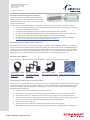
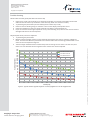
Operating instructions: EL-10-30-Series
Electrically focus tunable lens
Document number: 131-198-00
Date: 21.03.2014
Copyright © 2014 Optotune
Electrically focus tunable lens
EL-10-30-Series
Operating instructions
Safety warnings
Read these operating instructions carefully before using the product. It will help you operate the
product optimally, increase its lifetime and avoid problems and damage.
x Follow all safety instructions, including the instructions of any attached equipment
x No safety switch: Not adhering to the maximal electrical values can lead to malfunctions or
even damage the lens!
x Fire hazard: The lens can become very hot if operated at high currents
x Danger of leakage: A non-toxic fluid may leak if the lens is damaged
x This product is to be operated by qualified personnel only
These operating instructions are part of the product and are to be within reach at all times.
Should the product be re-sold or passed on to a third party, then these instructions must be
passed on together with the product.
Page 1 of 6
No representation or warranty, either expressed or implied, is made
W W W.as
S TtoEthe
Mreliability,
M E R- I completeness
M A G I N Gor
. Caccuracy
O M of this paper.
Optotune AG | Bernstrasse 388 | CH-8953 Dietikon | Switzerland
Phone +41 58 856 3000 | www.optotune.com | [email protected]
Operating instructions: EL-10-30-Series
Electrically focus tunable lens
Document number: 131-198-00
Date: 21.03.2014
Copyright © 2014 Optotune
Technical data
Operating voltage:
Internal resistance at room temperature:
Operating current (typical):
Absolute maximum current:
Maximal recommended power input:
Inductance of the motor:
0-5 VDC
12.5 Ohm
0-300 mA
400 mA
1.1 W (300 mA) in continuous operation
2.0 W (400 mA) short term (<1 minute)
10 Hz: 3.5 mH
1 kHz: 0.8 mH
50 Hz: 2.9 mH
10 kHz: 0.6 mH
100 Hz: 2.5 mH
100 kHz: 0.4 mH
Connecting the lens
All EL-10-30-Series lenses have an electro-magnetic motor, which is driven by current. The lens will only work
with the correct polarity of the current. False polarity will not damage the lens.
EL-10-30 (compact version)
The EL-10-30 has a simple copper cable connection. The correct polarity is shown in Figure 1:
+
Copper cable
–
Figure 1: Connection of the EL-10-30. The colored cable is the
positive terminal and the copper cable is the negative terminal.
EL-10-30-C (C-mount version)
The EL-10-30-C has an FPC connection compatible with Molex 0.5mm pitch 6 way FPC backflip connector (P/N
503480-0600). An adaptor board with integrated connector is included for easy soldering. The connector on
the adaptor board has top and bottom contacts so it is important that once orientation is established it must
be maintained.
The EL-10-30-C also features an integrated NXP SE97B temperature sensor with 256 bytes of memory – the
sensor is addressable via the pins as detailed below (I2C address is 0011000RW):
Pinning
Pin 1
Position
Function
SE97B Pins
1
SE97B Gnd
1-4
2
Lens (- pole)
-
3
Lens (+ pole)
-
4
SE97B SDA
5
5
SE97B SCL
6
6
SE97B Power
8
Figure 2: Connection of the EL-10-30-C (Orientation looking at exposed Cu tracks)
Page 2 of 6
No representation or warranty, either expressed or implied, is made
W W W.as
S TtoEthe
Mreliability,
M E R- I completeness
M A G I N Gor
. Caccuracy
O M of this paper.
Optotune AG | Bernstrasse 388 | CH-8953 Dietikon | Switzerland
Phone +41 58 856 3000 | www.optotune.com | [email protected]
Operating instructions: EL-10-30-Series
Electrically focus tunable lens
Document number: 131-198-00
Date: 21.03.2014
Copyright © 2014 Optotune
EL-10-30-Ci (industrial version)
For the industrial version EL-10-30-Ci the connection with the 6-pin Hirose connector is straight forward.
Pinning
Position
Function
SE97B Pins
1
SE97B SDA
5
2
SE97B SCL
6
3
SE97B Power
8
4
SE97B Gnd
1-4
5
Lens (- pole)
-
6
Lens (+ pole)
-
Operating the lens with a standard power supply
Several standard power supplies can be used as a current source. The internal resistance of the lens is of 12.5
Ohm at room temperature. Following Ohm’s law: U = R x I, 400 mA can be driven through the lens with a 5 V
supply voltage. This maximal value should not be exceeded. The recommended handling procedure of the lens
is as follows:
1.
2.
3.
4.
Set the supply voltage to 5 V
Switch over to current control
Connect the lens
Adjust the driving current with current control knob
Switch between voltage and current control
Voltage control
Current Control
Figure 1: Use of a standard power supply to drive the EL-10-30.
Left: Voltage display in volts. Right: Current display in milliamps.
The power consumption of the lens, derived from P = R x I2, is of 2 Watts at maximum. This consumption is dissipated in heat. The lens may become very hot if it is operated over a long period of time with more than 1.1
Watt power consumption (300 mA in terms of current).
Attention: Using a current over 400 mA for several minutes may thermally damage the lens!
Page 3 of 6
No representation or warranty, either expressed or implied, is made
W W W.as
S TtoEthe
Mreliability,
M E R- I completeness
M A G I N Gor
. Caccuracy
O M of this paper.
Optotune AG | Bernstrasse 388 | CH-8953 Dietikon | Switzerland
Phone +41 58 856 3000 | www.optotune.com | [email protected]
Operating instructions: EL-10-30-Series
Electrically focus tunable lens
Document number: 131-198-00
Date: 21.03.2014
Copyright © 2014 Optotune
Recommended drivers/power supplies
Optotune provides its own high-precision USB driver
with a resolution of 0.1mA. It includes the I2C readout
of the temperature sensor, which can be used for temperature compensation.
There are also many alternative off-the-shelf products available that can be used to control the EL-10-30:
x
x
x
x
x
Precision constant current driver for laser diodes with external control via 0-5V analog signal (e.g. Edmund Optics NT56-804 or NT84-355)
For high precision applications (0.1mA resolution) with manual control: TTi QL355
For high precision applications (0.1mA resolution) with USB/RS232 computer control: TTi QL355P
For low precision applications (1mA resolution) with manual control: TTi EL301R
For low precision applications (1mA resolution) with USB computer control: Quakko HY3005DP
http://shop.vendio.com/Evan2002/item/2041700966/?s=1282809362
Operating the lens with custom electronics
Dedicated control electronics can be designed e.g. by using pulse width modulation (PWM). The frequency in
this case should be set between 20 kHz and 50 kHz. Another very useful component is the ADN8810 programmable precision current source of Analog Devices, which features 12 bits of resolution and can be controlled
with an SPI interface. If the lens is operated with custom-built or non-certified electronics, Optotune cannot
guarantee the correct functioning of the lens and is not liable for any consequences of its use.
Mounting possibilities
The EL-10-30-C is compatible with C-Mount lens fixtures. Alternative mounting options include:
G024503000, LINOS
http://www.qioptiqshop.com/
G061042000, LINOS
http://www.qioptiqshop.com/
KM200V/M, Thorlabs
http://www.thorlabs.de/
NT03-676, Edmund Optics
http://www.edmundoptics.com/
Exchanging the offset lens in the EL-10-30-C
The EL-10-30-C is shipped with a planar cover glass or with an integrated offset lens (MV version), which is held
in place by a retainer ring. The cover glass or offset lens can easily be exchanged by hand following the procedure outlined below. Please note that this is preferably done in a clean room or under a flow hood to avoid
dust entering the tunable lens.
1.
2.
3.
4.
5.
6.
Loosen the retainer ring carefully with a small screw driver
After about 5 rotations turn the lens with the ring pointing down so no dust can get into the lens
Take out the cover glass / offset lens with the retainer ring. Prepare the new cover glass or lens.
Turn the lens again, but be careful, that no dust gets inside. Carefully drop the new cover glass or lens
(planar side should usually look down towards the lens) inside using tweezers.
Put the retainer ring in by hand
Tighten the retainer ring with a screw driver. Be careful not to scratch the glass.
IMPORTANT: At the end, do not exert much torque (<1 Nm) as this might damage the tunable lens.
Page 4 of 6
No representation or warranty, either expressed or implied, is made
W W W.as
S TtoEthe
Mreliability,
M E R- I completeness
M A G I N Gor
. Caccuracy
O M of this paper.
Optotune AG | Bernstrasse 388 | CH-8953 Dietikon | Switzerland
Phone +41 58 856 3000 | www.optotune.com | [email protected]
Operating instructions: EL-10-30-Series
Electrically focus tunable lens
Document number: 131-198-00
Date: 21.03.2014
Copyright © 2014 Optotune
1
4
2
3
5
6
Page 5 of 6
No representation or warranty, either expressed or implied, is made
W W W.as
S TtoEthe
Mreliability,
M E R- I completeness
M A G I N Gor
. Caccuracy
O M of this paper.
Optotune AG | Bernstrasse 388 | CH-8953 Dietikon | Switzerland
Phone +41 58 856 3000 | www.optotune.com | [email protected]
Operating instructions: EL-10-30-Series
Electrically focus tunable lens
Document number: 131-198-00
Date: 21.03.2014
Copyright © 2014 Optotune
Trouble shooting
The lens does not work (focal point does not move at all)
1.
Check if pins 2 and 3 (for EL-10-30-C) or cables (for EL-10-30) are correctly connected (note that the
cable of the EL-10-30 is only conductive at the cable tips, which are covered in solder)
Try switching the polarization (connect cables/pins the other way round)
Check if current is flowing using an ammeter or the current display of the power source
Check the impedance of the lens, which should be 12.5 Ohm at room temperature
If you cannot measure the right impedance or any current flowing at all, then an internal connection is
damaged and the lens must be replaced.
2.
3.
4.
5.
The focal point moves, but not as expected
Try switching the polarization
Measure the focal length and the current that flows through the lens with an ammeter at different
levels. The back focal distance (measured from the back side of the lens housing) should follow a curve
similar to the one depicted in Figure 3.
The focal length should decrease monotonously with increasing current. If this is not the case, then
there is an issue with the electro-magnetic motor and the lens must be replaced.
Back focal length [mm]
3.
220
210
200
190
180
170
160
150
140
130
120
110
100
90
80
70
60
50
40
30
20
10
0
EL-10-30-C with LD liquid
EL-10-30 LD material
EL-10-30 HR material
0
25
50
75
100
125
150
175
Current [mA]
200
225
250
275
300
Figure 3: Typical relation of focal length to current of different EL-10-30 configurations
Page 6 of 6
STEMMER IMAGI NG Head Office
Imaging is our passion.
No representation or warranty, either expressed
or implied, is9made
Gutenbergstraße
- 13, D-82178 Puchheim Optotune AG | Bernstrasse 388 | CH-8953 Dietikon | Switzerland
W W W.as
S TtoEthe
Mreliability,
M E R- I completeness
M A G I N Gor
. Caccuracy
O MPhone:
Phone +41 58 856 3000 | www.optotune.com | [email protected]
of this
paper.
+49
89 80902-0, [email protected]
www.stemmer-imaging.com
O-OPTU4-06/2015 ∙ Subject to technical change without notice. No liability is accepted for errors which may be contained in this document.
1.
2.