1
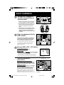
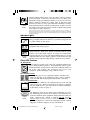
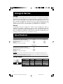
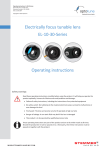
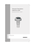
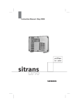
Owner's Manual
INTERNET I™
1111 W. 35th Street
Chicago, IL 60609 USA
Customer Support: +1 (773) 869-1234
www.tripplite.com
Safety:
Standby UPS Systems (230V)
ESPAÑOL: p. 7
FRANÇAIS: p. 13
p. 2
Quick Installation:
Basic Operation:
p. 4 - 5
Storage & Service:
p. 6
Specifications:
p. 6
p. 3-4
Warranty & Insurance: p. 6
Copyright ©2000 Tripp Lite. All rights reserved.
1
200008280 Internet I 230V Owner's Manual.p651
8/25/00, 2:34 PM
Safety
This manual contains important instructions and warnings that should be
followed during the installation, operation and storage of all Tripp Lite UPS
Systems.
UPS Location Warnings
• Install your UPS indoors, away from excess moisture, heat, dust
and direct sunlight.
• For best performance, keep the indoor temperature between 0° C and
40° C (between 32° F and 104° F).
• Leave adequate space around all sides of the UPS for proper ventilation.
UPS Connection Warnings
• Connect your UPS to a grounded AC power outlet. Do not remove or
modify the ground pin of the UPS's plug. Do not use plug adapters that
would circumvent the UPS's ground connection.
• Do not plug your UPS into itself; this will damage the UPS and void
your warranty.
• If you are connecting your UPS to a motor-powered AC generator,
the generator must provide clean, filtered computer-grade output.
Equipment Connection Warnings
• Do not use Tripp Lite UPS Systems for life support applications in
which a malfunction or failure of a Tripp Lite UPS System could cause
failure or significantly alter the performance of a life-support device.
• Do not connect surge suppressors to the output of your UPS. This may
damage your UPS and will void both the surge suppressor and UPS
warranties.
Battery Warnings
• Your UPS does not require routine maintenance. Do not open your
UPS for any reason. There are no user-serviceable parts inside.
• Battery replacement must be performed by qualified service personnel.
Because the batteries present a risk of electrical shock and burn from
high short-circuit current, observe proper precautions. Unplug and
turn off the UPS before performing battery replacement. Use tools
with insulated handles and replace the existing batteries with the
same number and type of new batteries (Sealed Lead-Acid). Do not
open the batteries. Do not short or bridge the battery terminals with
any object.
• The UPS batteries are recyclable. Refer to local codes for disposal
requirements. Do not dispose of the batteries in a fire.
• Do not attempt to add external batteries.
2
200008280 Internet I 230V Owner's Manual.p652
8/25/00, 2:34 PM
Quick Installation
1
Connect your computer to
the UPS, and the UPS to an
electrical outlet.
A
B
1. Unplug your computer’s power cord from both
your AC outlet and your computer’s AC input.
2. Insert the female plug of your computer’s cord
(B) into your UPS’s AC input. Insert the male
plug of your computer’s cord into your AC
outlet.
3. Find the power cord that came with your UPS
(A). Insert the UPS cord’s female plug into your
computer’s AC input. Insert the UPS cord’s
male plug into any of your UPS’s female output
receptacles.
2
Plug your equipment into the
UPS's outlets.
SEE MANUAL
Cords and receptacle adapters are available from
Tripp Lite to accommodate most outlet configurations. If rewiring is necessary, refer to the Wire
Color-Code Chart in "Specifications", pg. 6.
Your UPS is designed to support only computer equipment.
You will overload your UPS if you connect household
appliances, laser printers or surge suppressors to the
battery-supported outlets.
3
Set your UPS’s “OFF – ON” Switch.*
USA, Canada & Western Europe
• Set it and leave it “ON” at all times.
All Other Countries
• Set to “OFF” when you are not using connected equipment.
(WARNING! When set to “OFF,” UPS will not provide battery
backup during a blackout or brownout)
• Set to “ON” when you are using connected equipment.
*See Basic Operation section for the Switch Function, UPS Conditions and Setting Advantages.
–Optional Installation–
OPTIONS 1 & 2
(Select models)†
OPTION 1 (Phone-Line Surge Suppression)††
Using telephone cords, connect your wall jack to the
UPS jack marked “LINE” (or “IN”). Connect your
equipment to the UPS jack marked “EQUIP” (or “OUT”).
OPTION 2 (UPS Software)
Using Tripp Lite cable (if supplied), connect the DB9
port of your computer to the DB9 port of your UPS.
Load software (if supplied) and run installation
program appropriate for your operating system.
†These connections and settings are optional. Your UPS will
function properly without these connections and settings.
††Make sure the equipment you connect to the UPS’s
telephone jacks is also protected against surges on the AC line.
(Continued)
3
200008280 Internet I 230V Owner's Manual.p653
8/25/00, 2:35 PM
–Optional Installation–
(continued)*
OPTION 3 (Brownout Voltage Adjustment)
Adjust the Voltage Potentiometer (UPS back panel)
clockwise to lower the voltage point at which the
UPS switches from on-line to battery output.**
NORM
* Your UPS will function properly without these connections
or settings. ** Use caution when adjusting the potentiometer
while the UPS is powering a voltage-sensitive load.
Basic Operation
Switches
OFF
ON
Available
on select
models
With your UPS plugged in, set this switch according to the
recommendations in Step 3 of the Quick Installation section.
"ON" Position
Function: ENABLES battery backup. UPS Conditions: The UPS
battery is charging. Power is ON at the UPS receptacles. The " "
indicator light is illuminated. Setting Advantages: Provides
battery backup during blackouts or brownouts.
"OFF" Position
Function: DISABLES battery backup. UPS Conditions: The UPS
battery is charging. Power is ON at the UPS receptacles. The " "
indicator light is illuminated. The " " indicator light is flashing.
Setting Advantages: Continues to charge the battery when
power is present while turning OFF the inverter to prevent battery
backup operation when equipment is not in use.
Use this momentary switch to do three things:
Silence the UPS alarm*
Move this switch to the left and release it. Note: When the battery
is nearly depleted the alarm resumes (and cannot be silenced) to
alert you to immediately shut down connected equipment.
*The UPS alarm consists of a series of short beeps followed by a brief pause. The alarm is activated when
the UPS switches to battery during a blackout or brownout.
Test your UPS's battery charge**
With your connected equipment and your UPS turned ON, move
this switch to the left; hold it there for 2 seconds and release it. The
UPS will beep and flash its LEDs as it momentarily switches to
battery to test its charge. If the UPS alarm sounds afterwards, or
the properly-sized load is not supported, let your UPS charge its
batteries for 12 hours and repeat the test. If alarm still sounds,
contact Tripp Lite for service. CAUTION: Do not unplug your UPS to
test its batteries. This will remove safe electrical grounding and
may introduce a damaging surge into your network connections.
**If your model is not equipped with this switch, you can still test your UPS batteries. First plug your UPS
into a grounded surge suppressor (which will maintain the ground connection), then turn the surge
suppressor's power switch OFF.
4
Cold-Start your UPS
If your UPS is equipped with a MUTE/TEST switch, you may “cold
start” it and use it as a stand-alone power source when utility
power is not present, providing that the UPS's battery is charged.
To “cold start” your UPS, first turn the "OFF/ON" switch ON.
Then, move the MUTE/TEST switch to the left, hold momentarily
and release when the " " indicator light begins to flash.
200008280 Internet I 230V Owner's Manual.p654
8/25/00, 2:35 PM
NORM
Available
on select
models
Chronic mild brownouts that cause the UPS to switch to battery
power frequently could leave your batteries low on charge. The
adjustable voltage potentiometer allows you to prevent excessive
battery drain by lowering the voltage point at which the UPS
switches to battery. To keep your UPS from switching to battery
during mild brownouts, turn the potentiometer clockwise to lower
the voltage point as much as 18% below the nominal setting of 190
volts (when set fully clockwise).
Note: Your UPS’s optimal setting will depend on the voltage conditions in your area. Adjust the
potentiometer clockwise only if you want to reduce how often your UPS switches to battery. Your UPS will
function properly at any setting. Use caution when adjusting the potentiometer while the UPS is powering
voltage-sensitive loads.
Indicator Lights
All Indicator Light descriptions apply when the UPS is plugged into a wall outlet and turned ON.
This green light will turn ON whenever your UPS is plugged in and
receiving normal AC line power.
This red light will turn ON when your UPS is providing your
equipment with battery power.
Available
on select
models
This yellow light will turn ON after you test your UPS battery’s
charge with the “Mute/Test” Switch to indicate that the UPS’s
battery is less than fully charged. If it stays on continuously,
contact Tripp Lite for service. The light will flash after you set the
“OFF/ON” Switch to the “OFF” position to indicate that the UPS
will not provide battery backup during a blackout or brownout.
Other UPS Features
AC Receptacles
The receptacles provide your connected equipment with AC line
power during normal operation. They will provide battery power
during blackouts and brownouts only if the “OFF/ON” Switch is
set to the “ON” position. The receptacles also protect your
equipment against damaging surges and line noise.
RJ11 Telephone Jacks
These jacks protect your equipment against telephone line
surges. Connecting your equipment to these jacks is optional.
Your UPS will still work properly without this connection.
Battery Replacement Door
Under normal conditions, the original battery in your UPS will
last several years. Battery replacement should be performed
only by qualified service personnel. Refer to “Battery Warnings”
in the Safety section on page 2.
DB9 Serial Port
Available
on select
models
The DB9 port connects your UPS to any workstation or server.
Use with Tripp Lite software and cabling to automatically save
open files and shut down equipment during a blackout. This port
sends contact-closure signals to indicate line-fail and lowbattery status. It also receives a shut down signal from the
connected computer to conserve the UPS battery charge. Contact
Tripp Lite Customer Support for more information.
5
200008280 Internet I 230V Owner's Manual.p655
8/25/00, 2:35 PM
Storage & Service
Storage
First turn your UPS OFF and disconnect its power cord from the wall outlet.
Then disconnect all equipment to avoid battery drain. If you plan on storing your
UPS for an extended period of time, fully recharge the UPS batteries once every
three months by plugging the UPS into a live AC outlet and letting the UPS
charge for 4 to 6 hours. If you leave your UPS batteries discharged for an
extended period of time, they will suffer a permanent loss of capacity.
Service
If returning your UPS to Tripp Lite, contact your local Tripp Lite dealer or
distributor. You will be referred to a service center. Carefully pack the UPS
using the ORIGINAL PACKING MATERIAL that came with the unit. Enclose a
letter describing the symptoms of the problem. If the UPS is within the 2 year
warranty period, enclose a copy of your sales receipt.
Specifications
Output Capacity (VA/Watts):
Battery Runtime (Half Load/Full Load) Minutes:
Typical Runtime (Desktop PC/15 in. monitor) Minutes:
Battery Recharge Rate:
Approvals:
Modem/Fax Protection (starts at 260V):
Internet 300 I
Internet 500 I
300/185
17/5
15
2-4 hrs.
UL, CE
1 line
500/280
17/5
30
2-4 hrs.
UL, CE
1 line
Internet 700 I
Output Capacity (VA/Watts):
Battery Runtime (Half Load/Full Load) Minutes:
Typical Runtime (Desktop PC/15 in. monitor) Minutes:
Battery Recharge Rate:
Approvals:
Modem/Fax Protection (starts at 260V):
700/425
17/5
45
2-4 hrs.
UL, CE
1 line
ALL MODELS:
Input Voltage/Frequency (230V/60 Hz); On Battery Output Voltage Range (230V +/- 5%); Output Waveform Line Mode (filtered sine
wave); Output Waveform Battery Mode (PWM sine wave); AC Surge Suppression (exceeds IEEE 587 Cat. A & B standards); AC Noise
Attenuation (>40 dB); AC Protection Modes (H to N, H to G, N to G).
Wiring Diagram
Black
Brown
White
Blue
AMER
EURO
Green
Green/
Yellow
Wire Color
American
European
Wire Reference
American
European
Wire 1
Black
Brown
Wire 1
Line 1
Line 1
Wire 2
White
Blue
Wire 2
Neutral
Line 2 or Neutral
Wire 3
Green
Green/Yellow
Wire 3
Ground
Ground
6
200008280 Internet I 230V Owner's Manual.p656
8/25/00, 2:35 PM