1
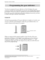
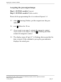
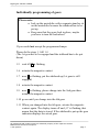
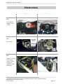
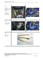
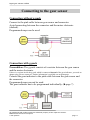
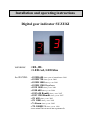
Installation and operating instructions
Digital gear indicator SUZUKI
versions:
• RL, BL
• LED red, LED blue
for SUZUKI:
• GSXR 600 since year of manufacture 2001
• GSXR 750 since y.o.m. 2000
• GSXR 1000 since y.o.m. 2001
• GSXR 1300 Hayabusa
• GSX 1400 since y.o.m. 2001
• GSR 600 since y.o.m. 2006
• GSF 650 Bandit since y.o.m. 2007
• GSF 1250 Bandit since y.o.m. 2007
• SV 650 since y.o.m. 2003
• SV 1000 since y.o.m. 2003
• V-Strom since y.o.m. 2002
• TL 1000R / S since y.o.m. 1998
• see actual list on www.tne-systeme.de
Digital gear indicator SUZUKI
Dear customer,
thank you for your purchase.
Please read the following instructions carefully, so you wouldn’t have any
difficulties to install the gear indicator. We wish you lots of success
installing the indicator and much pleasure using it.
The gear indicator has no approval to be used on public roads.
Warranty
We guarantee the function of the gear indicator two years
beginning on the day of purchase. Damages as a result of improper
installation make an exception of the guarantee.
Please tell us if you have any questions, suggestions for improvement or
experiences:
tne.systeme
Dipl.-Ing. T. Niedermayer
Alemannenstr. 7
D-73457 Essingen
Germany
tel: +49 7365 9191-41
email: [email protected]
web: www.tne-systeme.de
All trademarks and product names are industrial property of the respective owners.
Modifications and errors excepted.
© tne.systeme
page 1
Digital gear indicator SUZUKI
Installing the gear indicator
Safety and installation instructions
Please work carefully. Do not pull the cable or cable connections.
Improper cable connections may result in cable fires.
Improper cable installations or cable connections may result in
malfunction or damages to the gear indicator.
Correct laying and connection of cables is essential for long-term, errorfree function of the gear indicator.
The connector plugs at the gear indicator‘s cable have adjustments, please
notice that and plug in the connector very carefully to avoid damage of
pins.
- Install the cables along the original cable looms and connect them as
frequently as possible with insulating tapes or cable binders
- Use only the inserted connectors for connecting the cables
- We recommend to disconnect the battery before installing the cables
- To avoid interference from the ignition system do not put the cables
of the gear indicator near any parts of the ignition system
- Please install the plug-in connectors at a suitable place where no splash
water can reach them and keep care that they can not detach from their
place (use tape or cable binders).
- Do not locate the cables near sharp edges or hot or moving parts of the
motorbike.
- Please ask an expert if you have problems with the installation
Earthing cable connection
- Screw the cable with the ear on an earthing srew at the motorbike, do
not connect to a cable.
We are not responsible for consequential damages by installing and
using the gear indicator.
All trademarks and product names are industrial property of the respective owners.
Modifications and errors excepted.
© tne.systeme
page 2
Digital gear indicator SUZUKI
Installation
(see also pictures on page 9ff)
1.
Place the gear indicator with the adhesive tape at an adequate place.
The connection cable exits at the bottom. (►ill. 1)
2.
Find the gear sensor, maybe you have to remove some covers. The
gear sensor is near the place where the gearshift goes into the
gearbox (at SV 1000 and Hayabusa at the right side from the
motorbike above the brake lever)
The gear indicator has a beige cover and there are three cables
(blue, pink, black) connected in. (►ill. 2)
3.
Follow this cable to the connector (near the tank or the bench)
(►ill. 3)
4.
Connect the yellow cable of the gear sensor to the pink cable with
the inserted red clamp; put the gear sensor cable together with the
pink cable into the clamp and press it with a gripper.
DO NOT SHORTEN OR CUT THE GEAR SENSOR CABLE!
Please note the right connection on page 11, especially if you use a
g-pack. )
!
!
5.
Earth cable (black): Attach the cable with the ear to an earthing
screw on the motorbike or screw it onto the metalwork of the
motorbike, do not connect it to moving parts or with other cables.
Always ensure a good earthing connection. (►ill. 4)
6.
Plus cable (red): Clamp this cable with the inserted blue clamp to a
+12V cable (for example: ignition or light). You can use the cable to
the light or the green plug of the ignition switch. (►ill. 5)
7.
Program the gear indicator (see next page)
All trademarks and product names are industrial property of the respective owners.
Modifications and errors excepted.
© tne.systeme
page 3
Digital gear indicator SUZUKI
Programming the gear indicator
You have to program the gear indicator so that it displays the gears
correctly. For the most motorbikes you can use one of both maps that are
preassigned. These two maps are suitable for most SUZUKI-motorbikes.
If you use a g-pack or the gears will not be displayed correctly, you have
to break in the gear indicator individually.
General
So that the programming of the gear indicator is simple as it can be, you
can do it with the inserted magnet. Inside the gear indicator there is a
control element witch reacts to a magnet.
connection cable
magnet
gear indicator
When you approach the magnet parallel to the left side of the gearindicator in a distance of less than 8 mm (sideways or from top) you
actuate the magnetic contact. The gear indicator displays „_“, that
confirms the input, then take the magnet away and you can do the next
step for the programming.
All trademarks and product names are industrial property of the respective owners.
Modifications and errors excepted.
© tne.systeme
page 4
Digital gear indicator SUZUKI
Information:
If you do not actuate the control element during 30 sec., the
gear indicator displays E (error) and the existing adjustment
will be used.
Preparation
• The gear indicator is connected to the ignition:
1. turn off the ignition (gear indicator is out)
2. engage the 1st gear and put the sidehead down.
• Alternative: If the gear indicator is not connected to the ignition
1. turn off the ignition (gear indicator is out)
2. engage the 1st gear and put the sidehead down
Programming
1.1 Approach the magnet parallel to the left side of the gear indicator
1.2 Turn on the ignition (alternative: turn on the gear indicator, if it is
not connected to the ignition)
1.3 The display shows „_“, then take the magnet away
1.4 L (learning) flashes for 10 sec.
All trademarks and product names are industrial property of the respective owners.
Modifications and errors excepted.
© tne.systeme
page 5
Digital gear indicator SUZUKI
Accepting the preassigned maps
Map 1: SUZUKI- models 1 (preset)
Map 2: SUZUKI- models 2 (older models)
Please do the programming like it is written till point 1.4
1.5 when L (learning) flashes, put the magnet near the gear
indicator
1.6 now 1 flashes for 10 sec
1.7 if you want to use map 1, actuate the magnetic contact,
if you want to use map 2, wait till 2 is flashing and then
actuate the magnetic contact
1.8 The display turns off and „≡“ is flashing, that means that the
data is stored. If the sidehead is put up the gear indicator
displays the actual gear.
All trademarks and product names are industrial property of the respective owners.
Modifications and errors excepted.
© tne.systeme
page 6
Digital gear indicator SUZUKI
Individually programming of gears
Please note:
• Jack up the motorbike with a separate stand or sit
on the motorbike because the sidehead has to be
put up
• Keep care that the gears lock in place, maybe
you have to turn the backwheel
If you would not accept the programmed maps:
Please do the steps 1.1 till 1.4
(The 1st gear has to be engaged and the sidehead has to be put
down)
1.5 wait till C is flashing
1.6 actuate the magnetic contact
1.7 now 1 is flashing, put the sidehead up (1st gear is still
engaged)
1.8 actuate the magnetic contact
1.9 now 2 is flashing, please change into the 2nd gear then
actuate the magnetic contact
1.10 go on until you change into the 6th gear
1.11 When you changed into the 6th gear, actuate the magnetic
contact again. The display turns off and „≡“ is flashing, that
means that the data is stored. If the sidehead is put up the gear
indicator displays the actual gear.
All trademarks and product names are industrial property of the respective owners.
Modifications and errors excepted.
© tne.systeme
page 7
Digital gear indicator SUZUKI
Turn on and off the brightness control
In the gear indicator there is an automatic brightness control. You
can deactivate it then the brightness is only 85 %.
Do the programming as described from point 1.1 till point 1.4.
1.5 if L (learning) is flashing, actuate the magnetic contact
1.6 now 1 is flashing 10 sec., please wait
1.7 now 2 is flashing 10 sec., please wait
1.8 now H is flashing 10 sec., in this time actuate the
magnetic contact
1.9 The automatic brightness control is now changed, that means
when it was active it is now inactive or reverse
1.10 The display turns off and „≡“ is flashing, that means that the
data is stored. If the sidehead is put up the gear indicator
displays the actual gear.
Please note:
• If you want to accept programmed maps after
you changed the automatic brightness control,
the automatic brightness control is again active
(default).
All trademarks and product names are industrial property of the respective owners.
Modifications and errors excepted.
© tne.systeme
page 8
Digital gear indicator SUZUKI
Illustrations
Installation GSXR-600 (yom 2001) Installation SV 650 (yom 2004)
ill. 1
gear indicator
attached to the
cockpit
ill. 2
gear sensor
ill. 3
connector of gear
sensor (near
bench or tank),
clamp gear
indicator to the
pink cable
All trademarks and product names are industrial property of the respective owners.
Modifications and errors excepted.
© tne.systeme
page 9
Digital gear indicator SUZUKI
ill. 4
possible
connection of the
earthcable (red
circle),
connector of
gear sensor
(yellow circle)
ill. 5
possible connect
for plus cable
ill. 6
cables of gear
indicator
All trademarks and product names are industrial property of the respective owners.
Modifications and errors excepted.
© tne.systeme
page 10
Digital gear indicator SUZUKI
Connecting to the gear sensor
Connection without g-pack
Connect to the pink cable between gear sensor and connector.
Avoid connecting between the connector and the motor electronic
(dashed).
Programmed maps can be used.
connector
Connection with g-pack
Precondition: The g-pack consists of a resistor between the gear sensor
and the motor electronic.
If there is a resistor inside the g-pack which is connected instead of the gear indicator, you need an
adapter plug. Please contact us. Further information is available on our homepage.
Connect the gear indicator to the pink cable between the gear sensor and
the connector.
Programmed maps can not be used.
The gear indicator has to be programmed individually. (►page 7)
All trademarks and product names are industrial property of the respective owners.
Modifications and errors excepted.
© tne.systeme
page 11
Digital gear indicator SUZUKI
Troubleshooting
problem: After individual programming and sidehead put up the
gear indicator displays C instead of 1
solution: When programming individually the sidehead has to be put
down and the first gear must be engaged
problem: The gear indicator displays C all the time, the display of
the motorbike shows the error “FI”
solution: The shielded gear sensor cable of the gear indicator has a short
circuit. Maybe you have crimped the cable or damaged it in
any way. Please order a new cable set.
problem: The gear indicator displays C all the time, if the motorbike
is moved the gear indicator shows random gears.
solution: The pink cable of the gear indicator is connected to a wrong
cable. Make sure that the pink cable is connected to the white
plug with the three cables (pink, blue, black).
problem: When using a g-pack the gear indicator displays C all the
time
solution: You need an adapter plug that makes the gear indicator
working. Please contact us.
problem: The gears are displayed unreliably. For example when the
5th gear is engaged the gear indicator sometimes shows the
6th gear, etc.
solution: Some SUZUKI motorbikes emit much electromagnetic
radiation that influences the gear indicator.
=> Program the gear indicator specially as described on the
following pages.
All trademarks and product names are industrial property of the respective owners.
Modifications and errors excepted.
© tne.systeme
page 12
Digital gear indicator SUZUKI
Appendix
Specially breaking in the gears
If the gear indicator does not indicate the gears reliably and steady, neither
with the preassigned maps nor after the individual breaking, you can
activate a special breaking-program.
Please note:
• Jack up the motorbike with a separate stand or sit
on the motorbike because the sidehead has to be
put up
• Keep care that the gears lock in place, maybe
you have to turn the backwheel
• Do not turn on the motor
• Note: you may have a better programming result
when the motor is warm
1.0 Engage neutral (gear), put down the sidehead, turn off ignition
1.1 Approach the magnet parallel to the left side of the gear indicator
1.2 Turn on the ignition (alternative: turn on the gear indicator, if it is
not connected to the ignition)
1.3 The display shows „_“, then take the magnet away
1.4 L (learning) flashes for 10 sec., in this period actuate the magnetic
contact
1.5 one after one 1 , 2 , H , ° are flashing for 10 sec., wait
1.6 n flashes for 10 sec., in this period actuate the magnetic contact
All trademarks and product names are industrial property of the respective owners.
Modifications and errors excepted.
© tne.systeme
page 13
Digital gear indicator SUZUKI
1.7 now C is flashing. Engage the 1st gear and put down the sidehead
(if not done yet)
1.8 actuate the magnetic contact
1.9 now 1 is flashing, put the sidehead up (1st gear is still engaged)
1.10 actuate the magnetic contact
1.11 now 2 is flashing, please change into the 2nd gear then
actuate the magnetic contact
1.12 go on until you change into the 6th gear
1.13 When you changed into the 6th gear, actuate the magnetic contact
again. The display turns off and „≡“ is flashing, that means that the
data is stored. If the sidehead is put up the gear indicator displays
the actual gear.
Technical data
Dimensions:
display size:
operating voltage:
current consumption:
40x28x18mm (h x w x d) versions RL, BL
30x20x11mm (h x w x d) version LED
20mm all versions
9..15V protection against reverse polarity
20mA versions RL, LED
40mA version BL
protected against splash water, no loading of gear sensor signal
All trademarks and product names are industrial property of the respective owners.
Modifications and errors excepted.
© tne.systeme
page 14