1
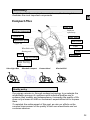
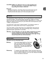
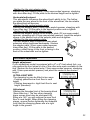
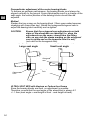
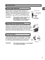
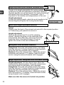
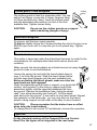
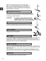
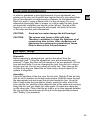
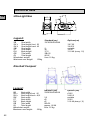
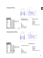
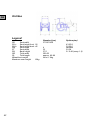
Sie Ihren Rollstuhl optimal nutzen können, lesen Sie die
D Damit
Gebrauchsanleitung vor dem Rollstuhleinsatz genau durch.
Inhalt
- Uebersicht
- Sicherheit
- Bedienung
- Bremsen
- Einstellmöglichkeiten
- Zubehör
- Wartung & Pflege
- Technische Daten
- Gewährleistungspflichten
3
4
5
7
9
13
17
18
21
To ensure that you can make the best use of your wheelchair,
GB please read the instructions thoroughly.
Contents
- Summary
- Safety
- Using the wheelchair
- Brakes
- Settings and adjustments
- Accessories
- Care and maintenance
- Technical data
- Warranty conditions
25
26
27
29
31
35
39
40
43
1
Summary
In order to make these instructions easier to use, the drawing below
illustrates the most important components.
GB
Compact Plus
Backrest
upholstery
Tipper aid
Wheelhub with
floating axle
Ultra-Light Neo
Küschall Compact
Contact Hemi
Küschall Kid
Quality policy
Our primary mission is, through modern technology, to accelerate the
rehabilitation process of customers with individual profiles and to
enhance their mobility and independance. Increasing the quality of life
does not just mean to fulfill our customer's expectations but to surpass
them.
To maintain the achievement of this goal, we aim our efforts on the
constant improvement of the quality of both our wheelchairs and our
customer-services.
25
Safety
GB
Please adhere closely to the following safety instructions:
Weight limitations
Maximum load: 120 kg (60 Kg for Kid Neo).
Pneumatic air pressure / Brakes characteristics
Sufficient air pressure should be kept in the tyres in order to maintain a
good performance of the brakes
Observe a weekly check of the tyre pressure!
Types of tyres
Lightweight tyre:
Sculpture tyre:
Lightwall-High pressure tyre
Sportshall tyre (Collé):
Air pressure
7 bar
7.5 bar
10 bar
10 bar
Floating axles
When operating the "quick Release" floating axles of the backwheels,
make sure each time that the axles are well engaged (see "Use: rear
wheels: assembly and removal").
Seat tubes
Whenever you unfold the wheelchair, ensure that the seat tubes are
fully engaged into the frame (see "Use: unfolding the wheelchair").
Leg supports
After every adjustment, check that the leg supports are well engaged
into the frame (see"Use:: unfolding the wheelchair").
Tilting
The rear wheel position is adjustable. Please note that such wheel
adjustments have an effect on equilibrium and/or the "stability" of the
wheelchair! The right seat position depends on factors such as the
body-weight, the type of handicap and the user's capabilities. Details
on the standard adjustments of the seat position are given on the
prescription form.
If you wish to determine the tilting-point of your wheelchair, make
sure somebody stands behind you, ready to prevent the
wheelchair from tipping backwards.
A more secure solution is to equip the wheelchair with an anti-tip device
from our range of accessories (see "Accessories: Swing-away anti-tip
device").
26
Threaded joints
Always tighten all screws and nuts firmly after each adjustment. Screws
may come slightly loose with time, especially when the wheelchair is
in constant use; we therefore advise you (or your Küschall/Invacare
dealer) to control the tightness of the screws monthly.
GB
Life expectancy
When the wheelchair is used on a daily basis, it is under constant
pressure and is subject to natural wear. Under such conditions, and
assuming the wheelchair is regularly serviced, the estimated life expectancy is 5 to 8 years for all Küschall wheelchairs. The more scarcely the
wheelchair is used, the longer this expectancy will be.
Using the wheelchair
In order to prevent any accident, please follow these instructions carefully:
Driving the wheelchair
- Avoid driving on steep surfaces and give special care in presence of
gravel or when the surface is either wet or uneven.
- Drive at night only under secure light conditions (see and be seen)
- Drive carefully over side obstacles, steps or door frames.
- Give special care when driving up-hill (best is to have a companion
standing at the back of the wheelchair).
- Always adjust your speed to the situation and the environment.
Transfers and loading of the wheelchair
Make sure you have been trained by professional staff before undertaking
such actions. If your legs cannot support your weight, a side transfer is
the solution: move the wheelchair alongside the object in question and
position it at a slight angle, so that the rear wheel and the footplate on the
transfer side touch it. Apply both wheel locks. Remove the armrest on the
transfer side. Move forward so that you sit on the front edge of the seat.
Place one hand on the surface you are transfering to and the other on the
frame or seat of the wheelchair. Then shift your centre of gravity towards
the object of transfer and pull yourself over.
Brakes
The supplied brakes are foreseen as immobilisation brakes. Using them
while in movement is not recommended. Should the brakes still be
misused, küschall design and Invacare cannot be held responsible.
General safety precautions and useful tips
- When entering or leaving your wheelchair do not stand on the footplates.
- Maintain proper balance at all times.
- Do not attempt to pick up objects by reaching between your knees.
- Do not attempt to reach objetcs by moving forward on the wheelchair.
- Do not lean over the top of the backrest
- Do not hang heavy loads or objects on the backrest.
27
GB
Unfolding the wheelchair
Tip the wheelchair slightly to one side so that
the load is taken from one driving wheel. Then
with your other hand push one of the seat tubes
downwards - the wheelchair unfolds.
Let the wheelchair go again so that it rests on all
four wheels. Now press both seat tubes into the
latches (pressure on both tubes is only necessary
whilst the wheelchair is new; once the folding
mechanism is running smoothly, pressure on one
seat tube will be sufficient).
Fitting the leg supports
Introduce the plastic pegs of the leg support into the top opening of
the frame as far as the stop, holding the leg support at a right angle to
the side frame. Rotate the leg support forwards until it engages and is
positioned parallel to the side frame. Repeat for the second leg support.
The footrest can now be folded down.
Folding the whleechair
If you have a seat cushion, remove it. Fold up the
footrest. Now hold the seat cover at the front and
the back and pull it upwards. This unlatches the
seat tubes and the wheelchair folds up.
Removing the leg supports
Pull the release lever back and swing out the leg
support simultaneously to an angle of 90° to the
side. The leg support can then be removed by
pulling it upwards. Repeat the procedures for the
second leg support.
Footplate
Palette
repose pieds
Rear wheels: Assembly and removal
When necessary, you can reduce the bulkyness of your wheelchair even
further by removing the backwheels. The "Quick Release" floating axles,
considerably simplify this operation.
Assembly
Release the brakes. Hold the wheel around the
hub, through the spokes with one hand. Press the
axle knob with your thumb and slide the wheel
into the axle plate socket until the stop. Release
the button - the backwheel is installed.
de roue
AdapterPalier
sleeve
28
CAUTION: Make sure that the axles are well engaged and
that the axle knob is not pressed down. Check
by pulling the wheels outwards.
GB
Removal
Release the brakes. Hold the wheel around the hub, through
the spokes with one hand. Press the axle knob with your
thumb and slide the wheel out of the axle plate socket.
Brakes
On wheelchairs a basic distinction can be made between parking brakes
and drum brakes. The parking brake operates by means of a lever
directly onto the tyres and is therefore highly dependent on a correct tyre
pressure. Always ensure that your tyres have the correct pressure (see
" Safety: Tyre pressure").
As mentioned in the name "parking brakes", this braking system is
designed as a safety brake and not as a stopping brake.
The drum brake, on the other hand, is not dependent upon the tyre
pressure and is therefore safer when travelling along. Furthermore,
graduated brake application is possible.
Warning: The wheelchair can only be safely braked at low speed
by the companion and remains steerable. Sudden
braking during travel may lead to the passenger being
thrown forward from the wheelchair.
Drum brakes
Operation by the attendant only!
Braking:
Press the brake handle on the hand
grip. To lock the brake in position,
pull the brake lever until the safety
lever locks. You can now release the
brake lever, and the wheelchair will
remain braked.
Releasing:
To release the locked brake: Press the brake lever and
push the small safety lever on the underside of the brake
lever, so that it unlatches. You can now release the brake
lever; the brake is released.
29
Standard brakes
GB
Actioning the brakes: push the brake handle down as
far as the stop.
Releasing the brakes: pull the brake handle back into
vertical position.
Pull brakes
The models with removable leg supports are, for safety reasons, only
fitted with the pull brake so that if the leg supports swing back the brake
cannot be released.
Actioning the brakes: pull the brake lever backward
as far as the stop.
Releasing the brakes: push the brake lever forward.
Performance brakes
Actioning the brakes: push the brake lever as far as the
stop. The gripper swings against
the backwheel.
Releasing the brakes: pull the brake lever back. the
brake gripper swings away from
the wheel.
Active brakes
Actioning the brakes: pull the brake handle to the
front, reaching either between
or beside your knees.
Releasing the brakes: push the brake handle back
under the seat cover, reaching
either between or beside your knees.
Stoplock brakes
Actioning the brakes: Lift the red handle positioned
on the rear wheel hub and
swing it to 180° so that it is
placed against the hub again.
Releasing the brakes: Swing the handle back into
closed position.
30
Settings and adjustments
GB
We advise you to call upon your Küschall / Invacare dealer for any
change or adjustment made on your wheelchair.
Every Küschall wheelchair is made-to-measure, according to the detail
given on the prescription form. A comfortable and energy sparing drive
can however depend on small adjustments which can only be carried
out once the wheelchair user has tried out his wheelchair. In order to
conduct these adjustments, this chapter will go through the various
adjustement possibilities. If you don't feel confident about making the
adjustments yourself, we advise you to turn to your dealer for help.
Adjustment of the brakes
To adjust the brakes, loosen the Allen screw situated on the clamp
(Allen key 5mm) and move the brake to the desired position.
Whenever there is a change to the rear wheel
position the brakes must be reajusted. The
distance between the brake gripper and the tyre
should be 25 mm, when the brakes are loose.
In the case of the Performance brakes and the
Active brakes, the brake gripper should penetrate no more than 4mm into the tyre, in the
activated position.
CAUTION:
Make sure that the air
pressure of your tyres is
convenient (see "Safety: Tyre
pressure").Tighten all screws
firmly!
25 mm
mm
15
Footrest height adjustment
To adjust the height of the footrest, slacken
the hexagon screws above the footrest using
the 8mm open-ended spanner whilst steadying
the 3mm hexagon head socket screw. Slide
the foot section telescope to the desired height
and insert the screws in the nearest holes.
CAUTION :
Ensure that the screws are
securely tightened.
Footsection
tube
telescope
telescopique
31
GB
Bottom tube adjustment with the Clamping System
In order to adjust the height of the footrest
slacken the hexagon head socket screw with the
5mm Allen key. Adjust the bottom tube length by
smoothly sliding it along the frame tube and retighten the screw.
Clamping
Bride de serrage
piece
If necessary, use a conical object to expand the
clamping piece so as to avoid damaging the
paintwork on the surface of the frame tube.
Height adjustment of the backrest tubes
If you have a clothes guard fitted, slacken the
screw on the rear frame tube (1). Remove the
hexagon socket screw below the frame tube (2).
If your model is fitted with a horizontal adaptor
plate, this must also be removed (3 + 4).Slide
the backrest tube to the desired position and
re-tighten all screws.
Adjusting the backwheel
Vertical adjustment
The adjustment of the backwheel
has an effect on the floor to seat
height and the seat angle and
thus also on the stability of the
chair:
a) If the wheel axle is fitted at the
top of the rear frame, the wheelchair will be less stable.
b) If the wheel axle is fitted at
the bottom of the rear frame, the
wheelchair will be more stable.
CAUTION :
Adaptor
sleeve
palier de roue
arrière
Adaptor
sleeve
Adaptor
plate
Plaque porte
Adaptor
roue
plate
If the seat angle is changed the front wheel
bearing block must be adjusted (see " Front wheel
adjustment").
- Method for the standard vertical adaptor plate:
Slacken the adaptor sleeve on the adaptor plate (22 mm open-ended
spanner, steadying with 22mm open-ended spanner). Insert the adaptor
sleeve in the desired hole of the adaptor plate and re-tighten.
- Method for the horizontal adaptor plate:
Slacken the adaptor plate (10mm open-ended spanner, steadying with
4mm Allen key). Fit the plate to the desired height and re-tighten.
32
- Method for the mini-adaptor plate:
Slacken the mini-adaptor plate (10mm open-ended spanner, steadying
with 4mm Allen key). Fit the plate to the desired height and re-tighten.
GB
Horizontal adjustment
This adjustment influences the wheelchair's ability to tip: The further
you place the rear wheel to the front of the wheelchair, the less stable
the wheelchair will become.
- Method for the vertical adaptor plate:
Slacken the adaptor plate (10mm open-ended spanner, steadying with
4mm Allen key). Fit the plate to the desired position and re-tighten.
- Method for the horizontal adaptor plate:
Slacken the adaptor sleeve on the adaptor plate (22 mm open-ended
spanner, steadying with 22mm open-ended spanner). Insert the adaptor
sleeve in the desired hole of the adaptor plate and re-tighten.
- Method for the mini-adaptor plate:
The mini adaptor plate is used as a rear wheel
extension when positioned backwards. Slacken
the adaptor plate (10mm open-ended spanner,
4mm Allen key). Fit the plate to the desired
position, either facing to the front or facing to the
back of the wheelchair and re-tighten.
Front wheel adjustment
Height adjustment
If your wheelchair model is equipped with a 5" or 8" front wheel fork, you
can position the front wheel in one of the other axle seats available on the
fork. Slacken the front wheel axle (13mm open-ended spanner, steadying
with 13mm open-ended spanner) and place the castor to the desired
height.
ULTRA-LIGHT NEO
The clamping lug can be fitted in two ways:
- Pointing upwards=low front floor to seat
height
- Pointing downwards = high front floor to seat
height (standard).
Adjustment
Slacken the threaded joint of the bearing Tête
block
de fourche
(5mm Allen key). The two other clampingorientée vers le haut
piece screws must also be slackened. By
fitting at a 180° you will achieve the new front
floor to seat height. When fitting the clamping
pieces, ensure (before tightening the threaded
joint) that the clamping pieces are at a right
angle to the ground.
Tête de fourche
orientée vers le haut
Tête de fourche
orientée vers le ba
Tête de fourche
orientée vers le bas
33
GB
Perpendicular adjustment of the castor bearing blocks
To achieve an optimum performance, the bearing blocks must always be
aligned vertically to the ground. Some Adjustments result in a change of the
seat angle. the vertical position of the bearing blocks should then be
adjusted.
Method
Slacken the two screws on the bearing block (10mm open-ended spanner,
steadying with 5mm Allen key). Rotate the hexagonal/octogonal cam to
adjust the bearing block vertically and re-tighten.
CAUTION:
Ensure that the octogonal cam adjustments on both
sides of the wheelchair are identical (i.e. when the
adjustments are the same, viewed from the fitting
side, on one side the stamp marking on the octogonal
cam is visible and on the opposite side it is not).
(not valid for the hexagonal cam)
angle d'inclinaison important
Large seat angle
angle d'inclinaison rédu
Small seat angle
Excentrique
à 8 Octogonal
pans
cam
Octogonal
Excentrique
cam
Fourche
Fork
à 8 pans
ULTRA-LIGHT NEO with titanium or Carbon front frame
Since the bearing blocks are fixed, no adjustment is possible.
Therefore, ensure that the seat angle of the wheelchair is always 4.2
+/- 1.5cm (seat angle = seat height at front - seat height at back).
34
Accessories
Backrest angle adjustment
Slide the bottom of the backrest upwards on the
backrest tube - 2 hexagon socket screws will
appear. Unscrew the bottom one completely (5mm
Allen key). The backrest angle can be set in one of
4 positions: 0°, 3°, 8° and 12°. Select the corresponding hole, replace the screw and tighten again.
CAUTION:
The position of the screws must
be identical on both sides.
If the backrest is set backwards,
the wheelchair is less stable. !
GB
Point
Hinge Fulcrum
d'articulation
Angle position
12°
Position de
réglage
for 3° 3°
and
Position
Angledeposition
réglage 0° + 8°
for 0° and 8°
Upholstered Velcro-adjustable back
Thanks to this Velcro system, you can decide on the
firmness of the backrest and adjust the comfort of the
wheelchair according to your needs: remove the padded
upholstery, loosen the Velcro bands at the back of the
backrest by simply pulling them apart. You can then
adjust them in the new desired position, to suit your back.
Folding hand grips
At the top of the backrest tube, just before the bend
on the hand grip, there is a metal sleeve. To collapse
the hand grip slide this sleeve upwards. If you wish
Bague
to replace the sliding hand grip in the vertical posi- Metal
Sleve
tion, lift the grip and slide the sleeve downwards.
CAUTION :
Poignée
Hand
grip
This folding hand grip is not designed
to overcome obstacles.
35
Height-adjustable push handles, mounted back
GB
Thanks to its height adjustability, this option enables your
companion to push the wheelchair comfortably. Because
the push handles are set backwards, the user's shoulders
will benefit from more freedom of movement. This is
important for the mobility and independance of the user.
Height adjustment
Loosen the locking handle, adjust the push handles to the
desired height and tighten the locking handle firmly.
Swivel and height adjustable armrests
Swivel
Slightly raise the back of the armrest and swivel it to the required position
or, if necessary, pull upwards to remove it.
Height adjustment
Remove the armrest (pull it out of the retaining
sleeve). Slacken the screw on the underside of the
armrest tube (4mm Allen key) and move the bolts
inside the tube to the desired height. Fit and retighten the screws in the next available hole.
Vis six pans
Swing-back and removable siderests
Swing-back: Press the side release buton, and swing
back the side rest. To bring it back into locked position,
swing the side rest forwards until it engages.
Removal: Press the release button. Swing the armrest
backwards and remove it. To replace, insert into back
socket, swing the armrest forwards until it engages.
Height adjustable, swing-back and removable siderests
Height adjustment: Pull the release lever. Move the
armrest to the desired position. Press the release lever
and slightly raise the upholstery until it engages.
Swing-back: Press the side release buton, and swing
back the side rest. To bring it back into locked position,
swing the side rest forwards until it engages.
Removal: Press the release button. Swing the armrest
back and remove it. To replace, insert into back socket,
swing forwards until it engages.
Make sure that the armrest is locked into position.
36
Clothes guard / Fixed mudguard
The clothes guard is fixed to a supporter plate. You can
adjust it as follows: loosen the 2 screws (spanner 8mm
or 10mm and Allen key 3mm). Level the clothes guard
with the backwheel and position it in front of the next
available hole. Tighten screws firmly.
CAUTION:
clothes
Kleiderguard
schutz
GB
Do not use the clothes guards as a support
while transfering (danger of injury)
Removable mudguard
To remove, pull the tyre covers upwards.
To Adjust, slighlty loosen the 2 screws binding the clip to the tyre cover.
Shift the tyre cover until it covers the tyre in an optimal way. Tighten
again.
Transit wheels
This option is necessary when the wheelchair becomes too wide for the
circumstances (for example when faced with narrow doors and
corridors).
When unused, the transit wheels are situated several cm away from the
ground in order to avoid disturbance.
Loosen the spring clip and slide the transit wheel down to
max. 2 cm from the ground. Slide the transit wheel further
until the snap head engages into the next available hole.
Before activating the transit wheels, make sure that the
snap heads are well engaged!
Place the wheelchair near a ramp or support, on a horizontal
surface. Hold yourself to the ramp or support and lift the
wheelchair slightly until the opposite backwheel lifts from
the ground. Remove the backwheel (see: Using the wheelchair: "rear wheel assembly and removal"). Set the wheelchair back onto the ground - it now rests on one transit wheel. Repeat
this operation on the other side - you can now drive on the transit
wheels, taking support on both sides of the alley to move forward.
CAUTION:
Please remember that the brakes have no effect
when using the transit wheels
To change back to the normal 24" backwheels, reverse this operation.
Tipper aid
On the standard versions of the Compact Plus and ContactHemi Plus, the tipper aid is integrated in the rear frame.
37
GB
With the design frame and on the Ultra-Light
Neo, you can adjust the position of the tipper aid.
Make sure not to adjust this position above the
outer diamter of the rear wheel (can be dangerous
when driving over a step)
Swing-away anti-tip device
This option stops the wheelchair from tiping backwards.
To inactivate the anti-tip, press it downwards and swing
it sideways inside the frame.
CAUTION:
In order to avoid a fall, the anti-tip
should imperatively be swung-away
whilst driving over a step or pavement.
Cane holder
Place the walking sticks into the holder and secure at
the top to the hand grip shaft with the Velcro fastener.
Lateral supports
Swing-away and adjustable
Passiv lights
Fix the passiv lights on the backrest upholstery. Minimum height from
the ground is 900mm. Maximum distance from the the side of the
wheelchair is 400 mm. Use both red reflectors on the backrest and fix
the yellow ones on the rear wheel spokes.
Tool-kit / Air-pump
The tool kit includes 2 Allen keys, 3mm and 4mm and 1 open-ended
spanners, 8mm and 10mm. With this kit, most of the adjustments can
be carried out.
The air-pump is delivered with a valve adaptor. Depending on the
size of the valve on your tires, this adaptor should be fitted on before
Security belt
Recommended when using drum brakes.
38
Care and maintenance
In order to guarantee a good performance of your equipment, we
advise you to carry out a carefull and regular check to your wheelchair.
Do not use abrasive or heigh pressure cleaners on the wheelchair.
Best is to wash it using a damp cloth or a bicycle spray. Dry your
wheelchair thoroughly after a shower or a drive under the rain. Axles
are especially important and should not be left wet. Spread a little
bicycle oil on a cloth and wipe the axle beads, the knob at the end
of the axles and the axles themselves.
CAUTION:
Sand and sea water damage the ball bearings!
CAUTION:
The screws may loosen a little with time.
Therefore, remember to check the tightness of all
screws from time to time. After slackening and
tightening the counternuts several times, renew
them to ensure their full performance.
GB
Tyre repair / change
Dismantle
Before repairing a damaged tyre, remove the wheel from the
wheelchair (see " Using the wheelchair: rear wheel assembly and
removal"). Press the valve until all remains of air are released. Lift one
tyre side wall (both if you are changing the tyre) from the rim, using a
bicycle tyre tool. Do not use a sharp or pointy tool. Then remove the
air tube from the tyre. Mend the air tube using a bicycle repair kit or
replace it altogether.
Assembly
Press the interface of the tyre over the rim side. Slightly fill the air tube
with air until it reaches its normal round shape. Slide the valve through
the appropriate hole and insert the air tube inside the tyre. Once the
tube is well inside the tyre without pleats, press the outer side of the
tyre over the rim, starting at the opposite side of the valve and pressing
along the rim until you reach the valve again. Procede the same way
on the other side. Check that the air tube is at no time trapped between
the tyre and the rim and pum-up the tyre to the appropriate pressure
(see "Safety: Tyre pressure).
39
Technical data
GB
Ultra-Light Neo
Legend:
SB
Seat width
SH v
Seat height front 50
SH h
Seat height back 45
SW
Seat angle
ST
Seat depth
RH
Back height
GB
Total width
GL
Total length
Wheelchair weight:
Maximum user weight:
120kg
Standard (cm)
33/36/39/42/45/48
5
40
37.5
SB+20
86-92
from 11.9kg
Options(cm)
39.7-55
34-50.5
variable
30-50
31.5-48 (every 1.5)
Küschall Compact
Legend:
SB
Seat width
SH v
Seat height front 50
SH h
Seat height back 46,5
SW
Seat angle
ST
Seat depth
RH
Back height
GB
Total width
GL
Total length
Wheelchair weight:
Maximum user weight:
120kg
40
Standard (cm)
33/36/39/42/45/48
3,5
40
42
SB+20
approx. 92-98
from 13.3kg
Options (cm)
43-55
34-50.5
variable
30-50
31.5-48 (every 1,5)
Compact Plus
Legend:
SB
Seat width
SH v
Seat height front 50
SH h
Seat height back 46
SW
Seat angle
ST
Seat depth
RH
Back height
GB
Total width
GL
Total length
Wheelchair weight:
Maximum user weight:
120kg
GB
Standard (cm)
33/36/39/42/45/48
Options (cm)
43-55
34-50.5
variable
30-50
31.5-48 (every 1,5)
4
40
37.5
SB+20
approx. 92-98
from 12.4kg
Contact-Hemi Plus
Legend:
Options (cm)
SB
Seat width
SH v
Seat height front 40.5
SH h
Seat height back 38.5
SW
Seat angle
ST
Seat depth
RH
Back height
GB
Total width
GL
Total length
Wheelchair weight
Standard (cm)
33/36/39/42/45/48
2
40
37.5
SB+20
approx.91-95
from 12.4kg
34-47.5
34.5-47
variable
30-50
31.5-48 (every 1,5)
41
GB
Kid Neo
Legend:
SB
Seat width
SH v
Seat height front 50
SH h
Seat height back 46
SW
Seat angle
ST
Seat depth
RH
Back height
GB
Total width
GL
Total length
Wheelchair weight
Maximum user weight
60kg
42
Standard (cm)
27/30/33/36
4
33
37.5
SB+20
approx. 85-89
from 11.9kg
Options(cm)
43-53.8
38-50.5
variable
30-38
31.5-48 (every 1.5)
Warranty terms and conditions
Standard terms
This is to certify that your küschall design wheelchair is warranted
by Invacare, for an unlimited period of time for the frame and
crossbars and 12 months for all other parts. This warranty is subject
to the following conditions:
1.
Only Küschall design wheelchairs purchased at full price are
warranted against defective workmanship and materials.
2.
If a defect or fault is discovered the Invacare dealer from whom
the appliance was purchased should be notified immediately.
3.
The manufacturer will not accept responsability for damage
caused by misuse or the non-observance of the instructions set
out in the user manual.
4.
During the period of the warranty, any parts that have become
defective due to faulty workmanship or materials, will be renewed
or repaired free of charge by the Invacare dealer.
5.
The warranty will be forfeited should any unauthorised alteration
be made to the equipment.
6.
The purchaser's statutory rights under the Consumer Protection
Act are not affected.
GB
Limitation of liability
This warranty does not extend to the consequential costs resulting from
fault clearance, in particular freight and travel costs, loss of earnings,
expenses, etc.
küschall design ag shall not be liable for:
- natural wear and tear
- unappropriate or incorrect use
- defective assembly or setting-up by the purchaser
or third parties
- defective or neglectful treatment
- use of unsuitable spares.
43