1
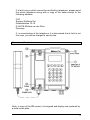
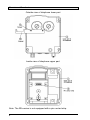
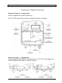
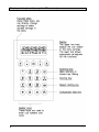
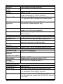
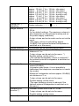
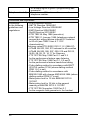
Explosion-proof telephone
Operating instructions
FHF BA 9701-22
05/13
Foreword
Our explosion-proof, weather-resistant telephone is a captivating
product on account of its precision, convenience, long service life and
reliability. It is freely programmable and the optimum choice for adverse
ambient conditions. Be it seawater, high atmospheric humidity, dust or
the toughest mechanical strains, the weather-resistant telephone
accomplishes its aim in any conditions. The reason for this is the robust
keypad made of V4A steel and an extremely solid housing made of
impact-resistant and shockproof cast-moulding material. All of the
components utilised are even resistant to leeches and lubricants. The
21-component V4A-steel keypad - which can be operated by a user
wearing gloves - and the easily readable alphanumeric display as well
as the uncomplicated menus all ensure simple operation - thus fulfilling
the requirements for a leading-edge and operationally reliable means of
communication. As a telephone suitable for connecting to the public
telephone network and to private automatic branch exchanges, the
ExResistTel always ensures reliable connections.
ExResistTel ZB is designed for telephone exchange operation and
corresponds to the ExResistTel, except for keypad and display.
2
Table of contents
General operating instructions ............................................................ 4
Overview of the device ........................................................................ 5
Display and keyboard ......................................................................... 8
Contents after unpacking .................................................................... 9
ZB version notes ................................................................................. 9
Explosion protection – device description ........................................ 10
Explosion protection – device construction ....................................... 11
Explosion protection – characteristic data ....................................... 14
Explosion protection – identification .................................................. 15
Assembly and installation ................................................................. 16
Connection diagram .......................................................................... 17
Sling holder ....................................................................................... 18
Drilling diagram ................................................................................. 18
Start-up ............................................................................................. 19
Maintenance...................................................................................... 19
Handset mode ................................................................................... 19
Open Listening .................................................................................. 19
Hands-free talking ............................................................................. 19
Working with the headset ................................................................. 20
Menu ................................................................................................. 21
Main Menu ........................................................................................ 22
Submenu: Telephone Book .............................................................. 23
Submenu: Change Telephone Book ................................................. 24
Submenu: Lock / PIN ........................................................................ 25
Submenu: Settings ............................................................................ 26
Submenu: Languages ....................................................................... 27
Default Settings ................................................................................. 27
Menu overview .................................................................................. 28
Technical data ................................................................................... 29
Guidelines and regulations ............................................................... 32
Service ............................................................................................. 33
Maintenance and servicing ............................................................... 33
Waste disposal .................................................................................. 33
Warning and safety instructions ........................................................ 33
CE symbol ......................................................................................... 35
EMC-Directive ................................................................................... 35
Index of catchwords .......................................................................... 36
EC Declaration of Conformity............................................................ 37
3
General operating instructions
1. Both the explosion-proof ExResistTel telephone and the ZB version
are designed for connection to dial ports with analogue connection
points.
2. The handset is fitted with a stray-field coil for connecting hearingaids. People who use hearing-aids which have an inductive receiver
can receive the earphone signal directly.
3. The optional, external loudspeaker has three operating modes –
calling/ringing, open listening and hands-free. If the external
loudspeaker is switched on, the internal loudspeaker volume will be
reduced.
4. The ZB version is not equipped with keypad and display, therefore
not all the features are available with this version.
5. The ExResistTel has a handset module with a dry reed contact as a
hook switch. In order to terminate an existing call connection, the
handset must be hung up. In order to interrupt an existing call
connection, it is sufficient to press the clearing key on the
keypad.(see page 8)
6. Use the menu to program the appropriate settings. To access the
menu, pick up the handset and press the "YES" key.
7. If you take longer than 2 minutes before you begin making a choice,
the power supply of the exchange may be switched off. If that
occurs, you will no longer hear a dialling tone. In that case, please
replace the handset and wait 2 seconds before picking it up again.
8. When a setting is stored successfully, this is confirmed by an
acknowledgement tone.
9. When you receive a call, the ExResistTel rings at the ringer-volume
level selected by you and, for the duration of the calling sound, the
symbols ( ( (
) ) ) appears on the display.
10. If you enter a PIN with the menu you can restrict or block dial
functions. Forgetting the PIN is the equivalent of losing a key. If you
forget the PIN, please contact our technical support.
11. You have a guarantee period of 24 months commencing from the
date of purchase. If you have a problem, please contact our
technical support in Germany, located in Mülheim an der Ruhr:
Telephone: 0208 82 68 102 · Fax: 0208 82 68 377
e-mail: [email protected]
From outside of Germany, please prefix the country code:
Telephone: +49 208 82 68 102 · Fax: +49 208 82 68 377
4
If a fault occurs which cannot be rectified by telephone, please send
the whole telephone along with a copy of the sales receipt to the
following address:
FHF
Support ExResistTel
Gewerbeallee 15-19
D-45478 Mülheim an der Ruhr
Germany
If, on examination of the telephone, it is discovered that a fault is not
the case, you will be charged a service fee.
Overview of the device
Note: In case of the ZB version, the keypad and display are replaced by
a solid metal plate.
5
Overview of the device
Outside view of telephone lower part
Inside view of telephone upper part
Note: The ZB version is not equipped with a pin contact strip.
6
Overview of the device
Inside view of telephone lower part
Protection Class II – Components
Factory supplied with: plastic cable entry.
Note: The ZB model does not have a keypad connector or display.
Screws
Loudspeaker
cable
Lower part
of telephone
Reed
switch cable
Display interface
connector
Keypad ribbon cable
with connector
Programming
interface connector
Sealing plug
Sealing plug
Protection Class I – Components
Factory supplied with: M20x1.5 threaded hole or a 1/2” NPT metal adapter for
connecting armoured cables or conduit systems.
Sealing plug
Sealing plug
Sealing plug
Sealing plug
Sealing plug
Metal adapter
7
Display and keyboard (except for ZB version)
8
Contents after unpacking
The delivery includes:
ExResistTel telephone
- Operating instructions
- 2 self-adhesive lettering plates
ZB version notes
The ExResistTel / ZB connects – depending on the features of the
PABX – with the PABX while lifting the handset. The ExResistTel / ZB
can be called also, because the ringing circuit is built in.
Furthermore there are interfaces for operating an optional second
earpiece, an optional secondary ringer and an optional external
loudspeaker.
The operating mode „external loudspeaker“ is set up by bridging the
terminals 9 and 10 (HSS1, HSS2). With the ZB version this is equivalent
to the open listening mode. The ringer sound is also output via the
external loudspeaker.
Note:
The set up of the external loudspeaker reduces the volume of the
internal ringer even if the external loudspeaker is not connected.
Thus the ZB version offers the following features:
•
•
•
•
•
Establishing a connection by lifting up the receiver
Ringing by means of integrated ringing device
Connection of second earpiece
Connection of secondary ringer
Connection of external loudspeaker
9
Explosion protection – device description
Regarding the explosion protection the ExResistTel telephone and the
ExResistTel telephone in ZB version are identical.
The explosion protection enables the user to make and receive calls
within hazardous areas of zone 1, in presence of an explosive gas or
dust atmosphere.
The ExResistTel telephone is manufactured in the following protection
classes:
II 2G Ex e mb [ib] IIC T5 Gb
II 2D Ex tb [ib] IlIC T100°C Db
-25°C ≤ Ta ≤ 60°C
II 2G Ex e mb [ib] IIC T6 Gb
II 2D Ex tb [ib] IlIC T80°C Db
-25°C ≤ Ta ≤ 40°C
DMT 02 ATEX E 183
Ex e mb [ib] IIC T5 Gb
Ex tb [ib] IlIC T100°C Db
-25°C ≤ Ta ≤ 60°C
Ex e mb [ib] IIC T6 Gb
Ex tb [ib] IlIC T80°C Db
-25°C ≤ Ta ≤ 40°C
IECEx BVS 11.0033
The ExResistTel telephone is designed for connection with analogue
telephone networks.
The non-intrinsically safe voltage of the telephone network is connected
to the terminals 13 and 14 (A, B) in increased safety. In calling/ringing
mode, this voltage is switched to the terminals 15 and 16 (Bell shunt1,
Bell shunt) in increased safety. The terminals 15 and 16 (Bell shunt1,
Bell shunt) are intended for passive consumers, e.g. a passive external,
explosion-proof secondary ringer.
Furthermore, a non-intrinsically safe voltage from the analogue
telephone network is turned into:
• an intrinsically safe receiver circuit with terminals on the inside of
the telephone housing, for use with the receiver, which is
permanently connected to the telephone housing, and
• intrinsically safe circuits with terminals within the telephone housing
for connecting an intrinsically safe headset or, optionally, an
intrinsically safe second earpiece, and
• an intrinsically safe circuit with terminals within the telephone
housing for the connection of an intrinsically safe loudspeaker.
The accessories headset, second earpiece, external loudspeaker and
external secondary ringer are not parts of the ExResistTel telephone,
but optional extras.
10
Explosion protection – device construction
The unvarnished housing of the ExResistTel telephone consists of an
electrostatically conductive cast-moulding equipped with a stainless
steel keypad. The keypad front plate contains a display sealed by a
viewing window.
The ZB version comprises no keypad and no display area, but a solid
front plate.
The housing consists of a rectangular lower part, in which there has
been placed a tray for mounting the electronic parts, as well as a
vaulted cover with a keypad.
The cover and the lower part of the housing, divided by a surrounding
seal only, are pressed together by four screws. The cover makes up
both the non-intrinsically safe and the intrinsically safe electrical
enclosure. The electronics circuit board is situated in the tray of the
lower part of the housing, completely embedded in a protective
compound.
Non-intrinsically safe terminals in increased safety:
Protruding from the compound (see connecting diagram on page 17), a
4-pole increased-safety terminal row is intended for connecting the nonintrinsically safe telephone network (A, B), terminals 13 and 14, as well
for connecting an optional, external, explosion-protected secondary
ringer (Bell shunt1, Bell shunt), terminals 15 and 16.
11
Intrinsically safe terminals:
Protruding from the compound (see connecting diagram on page 17), a
12-pole intrinsically safe terminal row is intended for connecting the
receiver, which is permanently connected with the telephone housing,
terminals 1 to 4, as well as the intrinsically safe accessories, terminals 5
to 12.
The terminals 7 and 8 are intended for the connection of dynamic
receiver insets, like the ones used in second earpieces and headsets.
This output thus can be used for connecting a second earpiece or a
headset, which means that a second earpiece and a headset cannot be
connected simultaneously.
Terminal
Note
1
2
3
4
Dynamic receiver inset connection 1
Dynamic receiver inset connection 2
Electret-foil microphone connection (+)
Electret-foil microphone connection (-)
5
6
Electret-foil microphone connection (+)
Electret-foil microphone connection (-)
7
8
Dynamic receiver inset connection 1
Dynamic receiver inset connection 2
Jumper between the terminals 9 and 10
is identified by the telephone as
headset connected.
or
– in case of the ZB version – as
external loudspeaker connected.
Dynamic loudspeaker connection 1
Dynamic loudspeaker connection 2
9
10
11
12
Use
Receiver inset
Receiver
microphone
Headset
Microphone, not for
ZB version
Headset or
second earpiece
Headset
identification or
–ZB version –
identification of
external
loudspeaker
External
loudspeaker
To connect accessories, you must replace the blind plugs screwed into
the telephone housing by explosion-proof cable glands (M20x1.5).
Before connecting intrinsically safe accessories, and if a system
certificate for the intended connection does not exist, the constructor
should perform an evaluation of the intrinsic safety according to the PTB
report “Zusammenschaltung nichtlinearer und linearer eigensicherer
Stromkreise“ (Interconnection of non-linear and linear intrinsically safe
electrical circuits), PTB-ThEx-10, from November 1999 (ISBN 3-89701440-9).
The technical data for the evaluation of the intrinsic safety can be found
in the chapter “Explosion protection – characteristic data”.
12
Further information see EN60079-14 “Electrical apparatus for explosive
gas atmospheres - Part14: Electrical installations in hazardous areas”
and EN50281-1-1 “Electrical apparatus for use in the presence of
combustible dust”. The user shall observe the standard EN50281-1-2
(IEC61241-1-2) if the device operates in hazardous areas with
combustible dust.
A metal bracket is supplied for hanging up the intrinsically safe second
earpiece or headset. The metal bracket should be attached to the
telephone by means of the two threaded bushes in the floor of the
telephone housing. The corresponding bores in the metal bracket can
be used to screw the bracket securely onto to the housing floor (see
overview of the device on page 6). Thus, if the constructor wants to use
the metal bracket, the first thing he has to do, is to fix it to the housing
floor. Subsequently, the device may be mounted on the wall.
Intrinsically safe programming interface
An 8-pole, intrinsically safe contact strip (14) (see overview of the device
on page 7) protrudes from the compound. This contact strip is
exclusively used by the manufacturer for programming purposes. Do not
switch any circuits by using the contact strip. The constructor may not
perform any kind of programming.
Intrinsically safe display interface
An 8-pole, intrinsically safe contact strip with a soldered-on circuit board
(15) (see overview of the device on page 7) protrudes from the
compound. The circuit board is equipped with a zero power plug for
connecting the intrinsically safe LC display film conductor. Connect the
built-in display only to this interface.
Intrinsically safe strand connection to the built-in loudspeaker
An intrinsically safe 2-pole strand conductor (16) (see overview of the
device on page ) goes from the compound to the built-in loudspeaker.
The strand is soldered onto the circuit board below the compound, as
well as onto the loudspeaker.
Intrinsically safe strand connection to the reed switch
An intrinsically safe, 2-pole strand conductor (17) goes from the
compound to a circuit board with a reed switch (see overview of the
device on page 7). On the compound-covered circuit board the strand
runs underneath the compound, and on the other circuit board it is
soldered onto the reed switch.
13
Intrinsically safe keypad connection
An intrinsically safe, 14-pole ribbon cable with plug bush (18) comes out
of the compound. Prior to screwing the device parts together, connect
this plug bush with the 14-pole pin contact strip in the housing cover.
Explosion protection – characteristic data
1. Non-intrinsically safe electrical circuits
1.1 Telephone network
(Terminals A / B No.: 13 – 14)
Maximum input voltage Um (ringing voltage)
Admissible frequency range
or
Maximum input voltage Um (supply voltage)
Maximum rated input current
Maximum input short circuit current IK
(At the input of this device there is a melting fuse
with a breaking capacity of 35 A)
AC 90 V
16...54 Hz
DC 66 V
100 mA
35 A
1.2 External secondary ringer:
For connection with passive consumers only
(Terminals Bell shunt1 / Bell shunt No.: 15 –16)
Maximum ringing voltage
Frequency range
or
Maximum supply voltage
AC 90 V
16...54 Hz
DC 66
2. Intrinsically safe electrical circuits
2.1
2.2
14
Headphones accessory (microphone)
(Terminal pair HSM No.: 5 – 6)
Maximum
output voltage
Maximum
output current
Maximum
output power
Maximum
external capacitance
Maximum
external inductivity
Uo
Io
Po
Co
Lo
17
90
80
375
1
V
mA
mW
nF
mH
Headphones accessory (receiver inset) or second earpiece
(Terminal pair HSR No.: 7 – 8)
Maximum
output voltage
Uo
17
V
Maximum
output current
Io
110
mA
Maximum
output power
Po
190
mW
Maximum
external capacitance Co
375
nF
Maximum
external inductivity
Lo
1.2
mH
V
2.3
2.4
2.5
Headphones accessory (identification)
(Terminal pair HSS No.: 9 – 10)
Maximum
output voltage
Maximum
output current
Maximum
output power
Maximum
external capacitance
Maximum
external inductivity
Uo
Io
Po
Co
Lo
17
8
33
375
100
V
mA
mW
nF
mH
External loudspeaker
(Terminal pair SPK No.: 11 – 12)
Maximum
output voltage
Maximum
output current
Maximum
output power
Maximum
external capacitance
Maximum
external inductivity
Uo
Io
Po
Co
Lo
6,6
250
370
22
0.3
V
mA
mW
µF
mH
All intrinsically safe output electrical circuits have a linear
output characteristic curve.
3. Ambient temperature range
-25°C < Ta < 60°C for temperature class T5
-25°C < Ta < 40°C for temperature class T6
Explosion protection – identification
Insulation class I
Insulation class II
Figure Type Plates
Telephone / Telephone ZB, Type ExResistTel
15
Assembly and installation
The device must be installed on a plane surface only, in vertical
operating position. Loosen the cover screws (2) (see overview of the
device on page 5 to 7). and detach the upper part of the telephone (1).
If the optional accessory headset or a second earpiece is being
employed, attach the bracket (10) using two screws (11) to the rear
panel of the lower part of the telephone. (With the accessories named
before, the bracket and screws are in the scope of delivery. With all
accessories a cable gland is delivered.) Put four screws, having a head
diameter of 10 to 13 mm into the holes (20) and attach the lower part of
the telephone (3) to the wall or to a holder.
Installation differs depending on the type of telephone model. On the
telephone with factory equipped plastic cable entry, the telephone network
cable should be passed through the cable entry (4) and connected to
terminals 13 and 14 (A, B) in accordance with the connection diagram. Only
use cables with a sheath diameter of 5 to 9 mm because otherwise the IP66
enclosure protection rating may be compromised.
On the telephone with the M20x1.5 threaded opening or the 1/2” NPT
threaded opening, the customer is responsible for mounting a cable entry.
Follow the manufacturer’s instructions supplied with the cable entry
assembly. Only cable entries with EU type approval for IP66 enclosure
protection rating and -25°C ≤ Ta ≤ 60°C should be used and they should
provide a good seal and fit tightly to the cable. On this model (Protection
Class I), make sure the PE (protective earth) wiring is connected properly.
Corresponding connection points are provided and marked inside and
outside of the housing. The telephone network cable must be connected to
terminals 13 and 14 (A, B) as shown on the connection diagram. If a torque
of more than 20 Nm is used to tighten down the sealing rings of the cable
entry, then the side of the cable entry assembly nearest the housing should
be secured against rotating.
Connecting a second ringer (bell-shunt) (optional accessory)
Remove the sealing plug (5) and tighten the M20x1.5 cable gland
cap. Insert the wire of the second ringer and place it on the terminals
in accordance with the connection diagram. Only utilise wires which
have a sheath diameter of 5 to 9 mm because otherwise the IP66
housing protection standard is not guaranteed.
Connecting an external loudspeaker (optional accessory)
Remove the sealing plug (6) and tighten the M20x1.5 cable gland
cap. Insert the wire of the loudspeaker and place it on the terminals
11 and 12 (SPK+,SPK-) in accordance with the connection diagram.
Only utilise wires which have a sheath diameter of 5 to 9 mm
because otherwise the IP66 housing protection standard is not
guaranteed.
16
Connecting a headset (optional accessory)
Remove the sealing plug (6) and tighten the M20x1.5 cable gland
cap. Guide the specially-manufactured wire with the headset socket
(included in the delivery of the headset) through the cable screw cap
and place it on the terminals 5 through 10 (HSM+, HSM-, HSR+,
HSR-, HSS1, HSS2) in accordance with the connection diagram.
Only the wire included in the delivery for the headset should be used
because otherwise the IP66 housing protection standard is not
guaranteed.
Connecting a second earpiece (optional accessory)
Remove the sealing plug (6) and tighten the M20x1.5 cable gland
cap. Insert the wire of the second earpiece and place it on the
terminals 7 and 8 (HSR+, HSR-) in accordance with the connection
diagram.
Prior to assembly, check cover seal for tightness.
Using the plug connector (7), plug the ribbon cable onto the pin contact
strip (8) in the upper part of the housing.
Attach the upper part of the telephone and fasten it to the lower part of
the telephone with the four cover screws (2).
Upon disassembly of optional accessories, suited blind plugs must be
used to close the resulting openings.
Connection diagram
17
Sling holder
The holding strength for the handset is continuously adjustable.
Loosen the screws (12) and move the stopping catches (13). Pushing
the stopping catches together increases the holding strength whereas
pulling them apart reduces it. Tighten the screws again.
Drilling diagram
For making a drilling template please use the following dimensions (in
mm).
The diameter of the drilled hole is dependent on the screw employed
(screw diameter max. 8 mm) and the type of supporting base material
(steel, wood, concrete, plasterboard etc.) and must be chosen
accordingly.
18
Start-up
The ExResistTel telephone is ready for operation as soon as it has been
connected to the telephone network.
Maintenance
The ExResistTel telephone contains no parts that have to be
maintained.
Handset mode (except ZB version)
When you pick up the handset, you are in handset mode. Using the
keys
and
, you can adjust the handset volume for talking. If you
wish to durably change the handset volume, use the menu "Settings /
Handset volume". Using the key
mode. If you keep the key
you can switch into open listening
depressed and replace the handset, you
switch to hands-free talking mode.
Open Listening mode (except ZB version)
Using the keys
and
, you can adjust the loudspeaker volume for
talking. If you wish to change the loudspeaker volume durably, use the
menu "Settings / Loudspeaker". The handset volume cannot be
changed in open listening mode. Using the key
handset mode. If you keep the key
, you can switch to
depressed and replace the
handset, you switch to hands-free-talking mode.
Hands-free mode (except ZB version)
If you switch on the ExResistTel using the key
free-talking mode. Using the keys
and
you are in handsyou can adjust the
loudspeaker volume for talking. If you wish to durably change the
loudspeaker volume, use the menu "Settings / Loudspeaker". You end
the call using the key
. If you pick up the handset, you switch to
handset mode.
19
Working with the headset (except ZB version)
If the headset has been connected correctly, it takes the place of handsfree talking. For this reason, hands-free talking with the headset is not
possible. If you switch on the ResistTel with the key
, you are
operating in headset mode. If you lift the handset while in headset
mode, the handset assumes a higher priority. That means that it is
possible to speak and listen using the handset but, in this mode, it is
only possible to listen with the headset.
Comparison of the operating states without and with connected
headset:
Operation without the headset
Operation with the headset
Handset mode
Handset mode with the headset
- Handset can speak and listen
- Headset can only listen
- Loudspeaker is off
Open Listening with the headset
- Handset can speak and listen
- Headset can only listen
- Loudspeaker is on
Headset mode
- Handset is replaced
- Headset can speak and listen
- Loudspeaker is off
Open Listening mode
Hands-free mode
Using the keys
and
you can adjust the headset volume for
talking. If you wish to durably change the headset volume, use the menu
"Settings / Headset Volume". You end the call using the key
20
.
Menu (except ZB version)
Starting the menu
Press the key
.
You are now situated in the main menu.
The top line of the display indicates the menu in which you are located.
The lower line indicates which menu item is selected.
Selecting menu items
Press the key
or
.
The upper line of the display remains unchanged. In the lower line, the
menu items available for selection change with each key-press.
Activating a menu item
Press the key
.
The menu item which was indicated in the lower line is now located in
the upper line. In the lower line, you see the additional options available.
Exiting the menu
Press the key
.
With each key-press, you jump to the previous menu. When you arrive
back in the main menu, you exit it with the next key-press
.
21
Main Menu (except ZB version)
With the aid of the key
following items:
•
Telephone Book
•
Change Phonebook
•
Lock / PIN
•
Settings
•
Languages
or
, you can make selections under the
For selecting a telephone number from the
telephone book memory.
For creating new telephone book entries
For modifying existing telephone book entries
For deleting existing telephone book entries
For changing to the submenu Direct call
For setting the complete lock
To permit selections from the telephone book
only
For disabling or enabling the main menu
items “Settings”, “Languages” and “Change
Phonebook”
For changing the PIN
For adjusting the ringer volume and changing
the melody
Adjust the loudspeaker volume
Adjust the handset volume
Adjust the headset volume
Adjust the LCD contrast
Set the dialling method
Set the flash time
Set the exchange number and pause
Restoring to the default dettings
Switch on/off an external loudspeaker
Wecome text
For selecting the menu language German
For selecting the menu language English
For selecting the menu language Spanish
For selecting the menu language French
For selecting the menu language Italian
When you select an item, you can activate it with the key
exit the menu with the key
22
.
. You can
Submenu – Telephone Book (except ZB version)
You have the option of dialling up to 50 telephone numbers from the
telephone book. To store and/or change numbers, see the menu item
"Change telephone book".
You can select from the telephone book entries using the key
or
.
Examples:
•
•
•
•
•
FIRE BRIGADE
999
SECURITY
110
FHF MUELHEIM
020882680
CANTEEN
123
etc.
dials the telephone number shown on the display
dials the telephone number shown on the display
dials the telephone number shown on the display
dials the telephone number shown on the display
dials the telephone number shown on the display
When you have selected a telephone number to call, you can dial it by
pressing the key
. You can exit the menu using the key
.
23
Submenu – Change Telephone Book (except ZB version)
You can store up to 50 telephone numbers and their associated names.
Enter the numbers and names in their order of importance because they
later appear on the display in the order in which they were entered (e.g.
fire brigade before canteen).
Caution: The menu item "Default Settings" deletes all telephone book
entries.
With the aid of the key
following items:
or
, you can make selections under the
• New Entry
To make a new entry
• Change Entry
To change an entry
• Delete Entry
To delete an entry
• Delete All
To delete the entire telephone book
When you have selected an item, you can activate it by pressing the key
. You can exit the menu using the key
24
.
Submenu – Lock / PIN (except ZB version)
When you call up the menu "Lock / PIN", you are prompted to enter the
PIN. The PIN consists of 4 digits. In the state when delivered, the PIN is
"0 0 0 0".
If you change the PIN, don´t forget the new PIN. Forgetting the PIN
is the equivalent of losing a key. If you forget the PIN, please
contact our technical support.
Technical support in Germany, located in Mülheim an der Ruhr:
Telephone 0208 82 68 102
Fax
0208 82 68 377
e-mail
[email protected]
From outside of Germany, please prefix the country code:
Telephone +49 208 82 68 102
Fax
+49 208 82 68 377
When you have entered the PIN, you can make selections under the
following items with the aid of the key
• Direct Call
or
:
To switch on the direct call
To enter the direct call number
• Total Lock
Locks the telephone preventing all outgoing calls
Caution: It is also not possible to dial emergency
telephone numbers
• Directory Only
Only permits outgoing calls to numbers contained
in telephone book
• Settings
For disabling or enabling the main menu items
“Settings”, “Languages” and “Change Phonebook”
• Change PIN
To change the PIN
When you have selected an item, you can activate it by pressing the
key
. You can exit the menu using the key
.
Note:
When the settings are disabled the main menu items “Settings”,
“Languages” and “Change Phonebook” are only accessible after
entering the PIN.
The menu item "Default Settings" resets all settings except, however,
the PIN you may have changed and the language.
25
Submenu – Settings (except ZB version)
With the aid of the key
following items:
•
Ringer
•
•
•
•
•
Speaker Volume
Handset Volume
Headset Volume
LCD Contrast
Dialling
•
•
Flash time
PABX Settings
•
•
Defaults
External Speaker
•
Welcome text
or
, you can make selections under the
- For setting the ringer volume
- For setting the ringer melody
- For setting the loudspeaker volume
- For setting the handset volume
- For setting the headset volume
- For setting the display contrast
- Dialling method DTMF/ duration 90 ms
- Dialling method Pulse Dial 2:1
- Dialling method Pulse Dial 1.5:1
- Dialling method DTMF / duration 70 ms
- Dialling method DTMF / duration = keypress
- Set the flash time, 40 ms to 399 ms
- Entry of the exchange number
- Deletion of the exchange number
- Setting the dialling pause after the exchange
number
- Reset to the state when delivered
- Switch on/off an external loudspeaker
Note:
The optional, external loudspeaker has three
operating modes ringing, open listening and
hands-free. If it is switched on, the internal
loudspeaker volume will be reduced.
- input of an individual text, which is indicated
in the display after taking off the handset.
For example:
BRANCH 170
EXTERNAL DEPOT
When you have selected an item, you can activate it by pressing the key
. You can exit the menu using the key
26
.
Submenu - Languages (except ZB version)
You can make selections under the following items with the aid of the
key
•
•
•
•
•
or
:
German
English
Spanish
French
Italian
For setting the menu language to German
For setting the menu language to English
For setting the menu language to Spanish
For setting the menu language to French
For setting the menu language to Italian
When you have selected an item, you can activate it by pressing the key
. You can exit the menu using the key
.
Default Settings
To enable you to use the telephone immediately after connecting it, we
have made default settings for general utilisation purposes.
Using the menu, you can alter these default values in accordance with
your own personal necessities and connection requirements.
Upon delivery of the telephone, the following default values are set:
• Telephone book:
deleted
• Repeat dialling:
deleted
• Direct call number:
deleted
• Exchange number:
deleted
• Ringer melody:
0
• Ringer volume:
6 (maximum value)
• Handset volume:
0 (normal value)
• Headset volume:
2
• Loudspeaker volume:
4
• Welcome text
FHF
• External loudspeaker:
switched off
• Dialling method:
DTMF, signal duration 90 ms
• Flash time:
80 ms
• LCD contrast:
5 (normal value)
• Pause length after exchange number: 3 seconds
• PIN:
0000
Caution!
Resetting to the default settings via the menu restores these default
values with the exception of the PIN and the language:
•
•
The PIN is not changed.
The language is not changed.
27
Menu overview (except ZB version)
Main Menu
Telephone Book
Name #1
To
Name #50
Change Telephone Book
New Entry
Change Entry
Delete Entry
Delete All
Lock / PIN
Direct Call
Activate
Change Number
Total Lock
Directory Only
Settings
Change PIN
Settings
Ringer
Volume
Melody
Speaker Volume
Handset Volume
Headset Volume
LCD Contrast
Dialling
DTMF 90ms
Pulse Dial 2.0 : 1
Pulse Dial 1.5 : 1
DTMF 70ms
DTMF
Flash Time
PABX Settings
Enter Exchange Code
Clear Exchange Code
Pause Exchange Code
Defaults
Ext. Speaker
Welcome text
Languages
German
English
Spanish
French
Italian
28
Telephone book entry #1 is dialled
To
Telephone book entry #50 is dialled
Add a new entry to the telephone book
A telephone book entry is changed
A telephone book entry is deleted
The entire telephone book is deleted
The direct call is switched on
Change or enter the direct call number
The telephone is locked completely
Telephone is locked except for numbers
in the telephone book
The main menu items “Settings”,
“Languages” and “Change Phonebook”
are disabled or enabled.
The PIN is changed (default 0000)
The ringer volume is set
The ringer melody is set
The loudspeaker volume is set durably
The handset volume is set durably
The headset volume is set durably
The LCD contrast is set
Sets the dialling method to DTMF 90 ms
Sets the dialling method to PDM 2: 1
Sets the dialling method to PDM 1.5: 1
Sets the dialling method to DTMF 70 ms
Sets the dialling method to DTMF
unlimited
Set the flash time to between 40 and 399 ms
Entry of an exchange number
The exchange number is deleted
Set dialling pause to between 1 and 6 s
Resets to the state when delivered and
the telephone book is deleted
Switch on/off external loudspeaker
change
Menu language German is activated
Menu language English is activated
Menu language Spanish is activated
Menu language French is activated
Menu language Italian is activated
Technical data
Warning!
In order to maintain the explosion protection it is of paramount
importance to observe the information given in the chapter “Explosion
protection – characteristic data” on pages 14 and 15.
Note:
Except for ZB version for items marked with an asterisk *).
Connection data
Supply voltage
Supply current
Ringer voltage
24 VDC to 66 VDC
15 mADC to 100 mADC
24 VAC to 90 VAC (calling frequency 21...54 Hz)
30 VAC to 90 VAC (calling frequency 16.6...54 Hz)
Ringer impedance Greater than 6.0 kΩ at 25 Hz and 24...90 VAC.
Greater than 4.0 kΩ at 50 Hz and 24...90 VAC.
Consultation hold
Flash function adjustable from 40 ms to 399 ms
key *)
via the menu.
Dialling method *)
PD or DTMF mode can be set via the menu.
DTMF mode in accordance with ITU-T
recommendation Q.23.
Pulse Dial mode with pulse pause ratio 1.5:1 or
2:1 (adjustable via the menu).
Exchange number*) An exchange number and dialling pause are
programmable to between 1 s and 6 s via the
menu.
Bell-Shunt
Possibility for connecting a second external ringer.
External speaker
Terminals for the connection of an external
speaker (optional accessory).
Headset *)
Terminals for the connection of a headset
(optional accessory).
Note: A headset or a second earpiece can be
connected, but not both simultaneously !
Second earpiece
Terminals for the connection of a second earpiece
(optional accessory).
Note: A headset or a second earpiece can be
connected, but not both simultaneously !
2
Connection
Up to 4 mm inflexible.
2
terminals
Up to 2.5 mm flexible.
29
Housing
Material
Height x width x
depth
Weight
Display *)
Keyboard *)
Glass-fibre-reinforced polyester
approx. 260 mm x 228 mm x 135 mm
approx. 5.5 kg
2-line alphanumeric display with pictograms.
Field of view approx. 78 mm x 26 mm.
- Metal keyboard with protection against ice.
- 21 keys with ABC inscription for name entries.
Position of
operation
Mounted upright on the wall. The device must be
mounted on a plane surface only.
Protection Class I
M20 x 1.5 threaded hole or threaded 1/2” NPT
adapter for cable entry assembly.
Plastic cable entry for cable diameters:
Ø 6 to 13 mm
Protection Class II
Handset
Sling protection
Handset cord
Earphone
Microphone
capsule
Noise suppression
Ambient conditions
Protection type:
Protection against
external
mechanical impacts
Operating
temperature:
Storage
temperature:
Additional features
Clearing key *)
Hook switch
Power supply
Meter-pulse lock
30
Integrated, adjustable sling protection.
Steel-reinforced steel-clad cord made of V4A.
Dynamic capsule with stray-field coil for the
inductive connection of hearing-aids.
Electret microphone
Greater than 3 dB by integrated speak-in horn.
IP 66 as per EN60529
IK 09 as per EN50102
-25°C to +60°C
(display does not operate below -20°C)
-25°C to +70°C as per IEC60721
Separate key
Dry reed contact without a mechanical cradle
- from the analogue telephone network.
- no additional mains supply required.
- Electrical attenuation for 12 kHz and 16 kHz
on the earphone greater than 30 dB with respect
to 1 kHz.
- Impedance (telephone connections A, B):
approx. 13 kΩ ( 1 Veff ; 12 kHz ; idle state)
approx. 4 kΩ (10 Veff ; 12 kHz ; idle state)
approx. 2.5 kΩ ( 1 Veff ; 12 kHz ; during a call)
approx. 2.3 kΩ (10 Veff ; 12 kHz ; during a call)
approx. 11 kΩ ( 1 Veff ; 16 kHz ; idle state)
approx. 4 kΩ (10 Veff ; 16 kHz ; idle state)
approx. 2.5 kΩ ( 1 Veff ; 16 kHz ; during a call)
approx. 2.3 kΩ (10 Veff ; 16 kHz ; during a call)
Optical call *)
signalling
Ringer volume
Ringer melodies *)
Open Listening
Hands-free *)
Handset loud
function *)
Menus *)
Display indicates ( ( (
) ) )
- Approx. 90dB(A) at a distance of 1 m at 50 VAC /
50 Hz
(In the default settings. The maximum volume is
also dependent on the selected melody and on
the power-supply conditions).
- 6-step volume and mute mode can be set via the
menu.
(The ringer volume is reduced by approx.
12 dB(A) if the optional external loudspeaker is
switched on in the menu).
10 melodies can be selected via the menu.
- Maximum volume approx. 68 dB(A) at a
distance of 1 m
- 7-step volume can be set via the menu. *)
- Durable setting via the menu *)
(The internal loudspeaker volume is reduced if
the optional external loudspeaker is switched on
in the menu).
- Function possible where ambient noise do not
exceed 68 dB(A).
(at greater noise levels, it is not possible to
understand the telephone conversation in handsfree mode).
- Maximum loudspeaker volume approx. 68 dB(A)
at a distance of 1 m
- 7-step volume can be set via the menu.
- Durable setting via the menu
(The open listening volume is reduced if the
optional external loudspeaker is switched on in
the menu).
- Handset volume from 0 dB to +12 dB.
- 7-step volume can be set via the menu.
- Durable setting via the menu.
- In German, English, Spanish, French and Italian.
31
Telephone book *)
- An audible signal is given if programming was
successful.
- A maximum of 50 entries with name and
telephone number.
Guidelines and regulations
Conformity
- ATEX Directive 94/9/EC
to the following
- R&TTE Directive 1999/5/EC
guidelines and
- Low Voltage Directive 2006/95/EC
regulations:
- EMC Directive 2004/108/EC
- RoHS Directive 2011/65/EC
- ETSI TBR 38: May 1998 (acoustics)
- ETSI TBR 21: January 1998 (telephone-network
access) but without device-internal DC limitation
to 60 mA (see TBR21 item 4.7.1 DC
characteristics)
Advisory notes ETSI EG201121V1.1.2 (1998-07):
- ATAAB AN 003, 004, 013 relevant to all countries
- ATAAB AN 005, 006, 007, 009, 010 and DE 03,
04,05, 08, 09, 12, 14, 17 for Germany
- FTZ 121TR8: May 1994 Part 2.1 and 2.2
for the performance feature open listening
- FTZ 121TR8: May 1994 Part 2.1, 2.2 and 3
for the performance feature hands-free talking
- Pulse dialling method in accordance with BAPT
223 ZV5 version 07.96 (where dialling method
PDM 1.5:1 is set)
- Pulse dialling method in accordance with
BS6305:1982 with change AMD 4558:1984 (where
dialling method PDM 2:1 is set)
- Meter-pulse lock for 12 kHz BAKOM 337/2.2:
12/1997
- Meter-pulse lock for 16 kHz in the general
meaning of BAKOM 337/2.2: 12/1997
- FTZ 121TR8: November 1993 Part 3.1
for the magnetic field generator in the handset
32
Service
You have purchased a state-of-the-art product manufactured by FHF
and subject to stringent quality controls. If you have questions regarding
the telephone or if a malfunction has occurred – even after the
guarantee period – please contact FHF (see page 4). Please have the
type and article number ready (these numbers can be found on the type
plate) when you contact us.
Maintenance and servicing
The telephone is maintenance-free. Nevertheless, if the telephone is
deployed in areas with significant impurities due to dust, grease, oil etc.,
then it should be cleaned from time to time. The handset and the
telephone should be wiped with a damp cleaning cloth. Caution! Never
use sharp objects for cleaning.
Waste disposal
The device may be completely recycled as electronic waste. Upon
disassembling the device, the plastic, metal and electronic components
must be disposed of separately.
In every single case the national requirements and regulations for waste
disposal must be observed.
The waste-disposal requirements of your country must be observed.
Warning and safety instructions
This equipment is an explosion-proof and weather-resistant telephone
specifically designed for operation in a harsh industrial environment.
The following warning and safety instructions must be heeded:
1. Do not connect or operate the telephone with voltages other than
the voltages specified. Make sure the PE wiring is connected
properly on the Protection Class I model. All cabling should be
routed such that it does not present a tripping hazard.
2. The telephone must only be operated under the specified ambient
conditions (see section "Technical data"). Adverse ambient
conditions, such as e.g. ambient temperatures which are too high or
too low, are not permissible because this promotes the failure of
electronic components.
3. It must be ensured that the telephone, the connection wire etc. are
not damaged. It is not permissible to operate the telephone in a
damaged state.
4. The circuits of the telephone must not be earthed.
5. When operating the telephone, please heed the legal and
commercial / industrial regulations, accident-prevention regulations
and electrical regulations / provisions.
6. Repairs are only permissible with original spare parts which must be
replaced by a specialist. Other replacement parts can cause
damage and render the guarantee invalid.
33
7. The stipulated position of utilisation must be adhered to. The
telephone must be installed on a plane surface only, in vertical
operating position.
8. Magnetic fields with energy technical frequencies can cause a slight
impairment of the listening quality. If this is the case, please ensure
that the telephone is installed at a suitable location.
9. The type of protection of the telephone is:
II 2G Ex e mb [ib] IIC T5 Gb
Ex e mb [ib] IIC T5 Gb
II 2D Ex tb [ib] IlIC T100°C Db
Ex tb ] IlIC T100°C Db
-25°C ≤ Ta ≤ 60°C
-25°C ≤ Ta ≤ 60°C
II 2G Ex e mb [ib] IIC T6 Gb
Ex e mb [ib] IIC T6 Gb
II 2D Ex tb [ib] IlIC T80°C Db
Ex tb [ib] IlIC T80°C Db
-25°C ≤ Ta ≤ 40°C
-25°C ≤ Ta ≤ 40°C
DMT 02 ATEX E 183
IECEx BVS 11.0033
10. The telephone must be switched off before opening. Wait at least 2
minutes after switching off power before opening the telephone!
11. In the open state of the telephone no dust may ingress the device.
12. Upon mounting or demounting the device, do not damage the cover
seal, which keeps the cover tight, or the collar on the lower part of
the housing.
13. Upon repairing the apparatus for use in dust, the repaired parts
should once again be subjected to a routine test.
14. The mouthpiece horn of the receiver consists of a non-conductive
plastic material. It may become dangerously charged at high air
speeds. Consequently, cleaning the mouthpiece horn with
pressurized air is prohibited.
15. If there is a high concentration of sulphurous gases in the
environment, the lettering of the keys can fade and a rust film can
arise.
16. Changes to the product which are in the interests of technical
progress are possible even without prior notice.
34
CE symbol
The ExResistTel fulfils the requirements of the following directives:
R&TTE Directive 1999/5/EC
Low Voltage Directive 2006/95/EC
ATEX Directive 94/9/EC
EMC Directive 2004/108/EC
RoHS Directive 2011/65/EC
The conformity with the above directives is confirmed by the CE
marking.
35
Index of catchwords
Assembly ................................
CE symbol ..............................
Change telephone book ........
Complete lock .......................
Connection diagram ...............
16
35
24
25
17
Default settings ..................... 27
Direct call ............................... 25
Display and keyboard ............... 8
Display contrast ..................... 26
Drilling diagram ..................... 18
DTMF .................................... 26
EC Declaration of conformity .
EMC-Directive ........................
Exchange number ..................
Explosion protection –
characteristic data ...............
device construction .............
device description ...............
identification ........................
External loudspeaker ............
External Ringer (Bell-shunt) ...
37
35
22
14
11
10
15
16
16
Flash ..................................... 26
Foreword ................................. 2
General operating
instructions .............................. 4
Hands-free talking .................
Handset mode .......................
Handset volume ....................
Headset .................................
19
19
19
20
Installation ............................. 16
36
Languages ............................ 27
Lock / PIN .............................. 25
Loudspeaker volume ............. 19
Maintenance and servicing ...
Main menu ............................
Menus ...................................
Menu overview .......................
33
22
21
28
Open Listening ...................... 11
Overview of device .................. 5
Packing contents ..................... 9
Pause after exchange
number .................................. 26
Pulse Dialling ......................... 26
Ringer melody ....................... 26
Ringer volume ....................... 26
Second earpiece .................
Secondary ringer
(Bell-shunt) ............................
Service ..................................
Settings .................................
Sling holder ............................
17
16
33
26
18
Technical data ....................... 29
Telephone book .................... 23
Warning and safety
instructions ............................. 33
Welcome text ........................ 20
ZB version notes ...................... 9
37
Subject to alterations
or errors
FHF Funke + Huster Fernsig GmbH
Gewerbeallee 15-19 · D-45478 Mülheim an der Ruhr
Phone +49 / 208 / 82 68-0 · Fax +49 / 208 / 82 68-286
http://www.fhf.de · e-mail: [email protected]