1
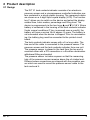
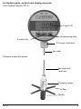
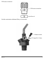
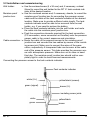
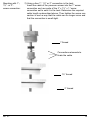
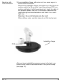
Operating Instructions
Digital Tank Contents Indicator DIT 01
DIT 01
AN 52122
DIT 01-E
AN 52123
Read instructions before using device!
Observe all safety information!
Keep instructions for future use!
Druckstand: 12.2005
Id.-Nr.: 854.001.0335
Contents
1 Applications ..............................................................................3
2 Product description ................................................................4
2.1 Design ..............................................................................4
2.2 System parts, controls and display elements ....................5
2.3 Function ............................................................................8
2.4 Specifications ....................................................................8
2.5 Scope of delivery................................................................9
3 Mounting and operation ........................................................10
3.1 Tank data determination ..................................................10
3.2 Installation and commissioning ......................................11
3.3 Measuring ......................................................................17
3.4 Maintenance ....................................................................18
4 Appendix ................................................................................19
4.1 Spare parts, accessories ................................................19
4.2 Warrantee ........................................................................19
4.3 Copyright ........................................................................20
4.4 Liability information ........................................................20
4.5 Addresses ......................................................................20
DIT 01
2
1 Application
The DIT 01 digital tank contents indicator is suitable exclusively
for the measurement of filling levels in heating oil tanks with
heights up to 3 metres.
Any use other than the use explicitly permitted in this instruction
manual in not permitted.
Changes made to the product by unauthorised persons may lead
to incorrect readings and are prohibited for reasons of safety.
Afriso-Euro-Index shall not be liable for damages resulting from
such tampering or for damages resulting from any use other than
the use explicitly permitted in this instruction manual
Attention!
The tank contents indicator DIT 01 must not be operated in hazardous areas.
DIT 01 may only be installed by authorised, qualified experts in
accordance with these operating instructions.
The warrantee shall be void in the case of improper installation.
The tank contents indicator DIT 01 is not a safety device. It does
not replace the function of a limit value transducer at the heating
oil tank.
The tank contents indicator DIT 01 may only be installed in
unpressurised heating oil tanks. A tank vent installed in accordance with the pertinent regulations as well as a limit value
transducer are required.
The cable entry point of the pressure sensor into the heating oil
tank must be significantly higher than the maximum filling level
and must be sealed with the enclosed screw connections in such
a way that no oil vapours can escape and that the pressure sensor cannot move vertically
The measured values displayed, especially the litre indication
values, must not be used for billing purposes. The accuracy of
the measured values displayed depends on the accuracy of the
tank data determined and entered. Therefore, the manufacturer
cannot guarantee the accuracy required for billing purposes.
DIT 01
3
2 Product description
2.1 Design
The DIT 01 tank contents indicator consists of an electronic
pressure sensor and a microprocessor-controlled indication system contained in a sturdy plastic housing. The measured values
are shown on a 4-digit liquid crystal display (LCD). The function
key F allows you to switch on the device and select the display
modes litres, cubic metres, percentage and filling level. The
device is programmed via the two keys
and
A 3.6 V lithium
battery is contained in the housing of the tank contents indicator.
Under normal conditions (F key is pressed once a month), the
battery will have a service life of approx. 8 years. The battery is
not connected when the device is shipped. Prior to commissioning, the battery plug must be connected to the printed circuit
board.
The tank contents indicator comes with a 5 m long cable. The
free end of the cable is connected to the pressure sensor. The
pressure sensor and the tank contents indicator form one unit.
The pressure sensor is placed in the tank from the top and is
mounted either with a PG connection or a Euroflex combination
withdrawal fitting and sealed.
The pressure sensor includes a spacer so that the measuring
hole of the pressure sensor remains above the oil sludge level.
Different screw connections are shipped with the pressure sensor which are used to mount the pressure sensor cable to the
tank and seal it.
DIT 01
4
2.2 System parts, controls and display elements
Tank contents indicator DIT 01:
4-digit LCD
Programming keys
Function key
PG screw connection
5m cable
Pressure sensor with spacer:
5m cable with
vent tube
Pressure sensor
Star
Spacer
DIT 01
5
Wall holder for DIT 01:
Screw connection set 2" x 1½" 1":
Screw connection 1":
DIT 01
6
PG9 screw connection:
PG9 screw connection
Hex nut
Euroflex combination withdrawal fitting, not connected.
Pressure screw
2 O-rings 6,5 x 1,5mm
DIT 01
7
2.3 Function
The pressure sensor is located at the lowest point of the heating
oil tank and transforms the hydrostatic pressure of the heating oil
into an electrical signal. The measuring signal is transmitted to
the tank contents indicator via the cable. The electronic system
of the tank contents indicator uses this signal to calculate the
tank contents, which it displays in litres, cubic metres, percentage or filling level. The display mode is selected by means of the
F function key. The tank data is entered via the two programming
keys.
2.4 Specifications
Pressure sensor:
Dimensions:
Weight:
Cable length:
Pressure range:
Housing:
Cable:
Spacer:
Additional parts coming into
contact with the medium:
Protection:
Permissible ambient temperature:
Accuracy*:
Temperature error:
Noise suppression:
Noise immunity:
Tank contents indicator: Dimensions:
Weight:
Housing material:
Cable length:
Power supply:
Battery life:
Display:
Resolution:
Measuring input:
Accuracy*:
Permissible ambient temperature:
Protection:
Noise suppression:
Noise immunity:
ø=25mm, L=107mm
410 g
5m
0-300mbar
Stainless steel 1.4305
Heating oil-resistant PVC
POM, PE
Ceramiks, silicon, silicone glue,
Viton
IP 68 EN 60529
0°C to 60°C
< ± 1,0% FSO, IEC 60770
< ± 2% FSO, 0 to 60°C
According to 50081-2
According to 50082-2
ø=75mm, H=50mm
380 g
PA6 15%, glass ball reinforced
5m
3.6 V lithium battery
Max 8 years, depending on usage
4-digit LCD
14bit
0 to 3,6V
< ± 1,0% FSO, IEC 60770
0 to 45°C
IP 51 EN 60529
According to EN 50081-1
According to EN 50082-1
Accuracy of complete system *: < ± 1,5% FSO, IEC 60770
* With reference to the filling level indication in mm.
DIT 01
8
2.5 Scope of delivery
DIT 01 Item no Art.-Nr. 52122:
Tank contents indicator DIT 01
Pressure sensor with spacer
Connection set 2" x 1½" x 1"
Screw connection 1"
Screw connection PG9
Moisture-proof junction box
Insulating screw joint, 4 poles
Wall holder for DIT 01
Operating instructions
DIT 01-E Item no Art.-Nr. 52123:
Tank contents indicator DIT 01
Pressure sensor with spacer
Euroflex combination withdrawal fitting with 3.1 m suction tube
2 O rings 6.5 x 1.5 mm
Pressure screw
Moisture-proof junction box
Insulating screw joint, 4 poles
Wall holder for DIT 01
Operating instructions
DIT 01
9
3 Mounting and Operation
3.1 Tank data determination
Before the DIT 01 tank contents indicator is installed, you must
determine the appropriate tank data. Please document the tank
data on this page for safety reasons and to allow for subsequent
checks.
1. Tank shape
Refer to the table below to find the appropriate code for the tank
shape. If you want a linear indication, use the code 1.
Tank shape
Tank shape
Description of tank shape
code
1
Linear tank
Rectangular tanks, upright, cylinders, steel tanks welded in base
ments, all other linear measuring
applications.
2
Tubular tank
Vertical cylinder
3
Ball-shaped tank Ball-shaped tank
4
Plastic battery
Plastic battery tanks with
tank
armouring or arches
5
Oval tank
Oval basement tanks, e.g glassfibre reinforced tanksor steel sheet
tanks
6
Plastic tank with Plastic tanks with major recess
recess
major in the centre (manufacturers: e.g. Roth, Werit)
Enter the tank shape here:
Tank shape code:
2. Tank volume
Determine the total volume of the tank facility in litres and enter
it here:
Tank volume:
in litres
3. Tank height (max. filling level)
Determine the tank height in mm and enter it here:
Tank height:
mm
4. Current filling level
Determine the current filling in mm level as exactly as possible
and enter it here:
mm
Current filling level:
DIT 01
10
3.2 Installation and commissioning
Wall holder:
Use the enclosed screw (4 x 30 mm) and, if necessary, a dowel
(6mm) to mount the wall holder for the DIT 01 tank contents indicator at the desired location.
Moisture-proof
Use the enclosed screws and, if necessary, dowels, to mount the
junction box:
moisture-proof junction box for connecting the pressure sensor
cable and the cable of the tank contents indicator at the desired
location. Make sure to provide sufficient cable length. The tank
contents indicator must be able to be removed from the wall
holder, e.g. if you need to replace the battery.
Place the tank contents indicator into the wall holder and route
the cable into the moisture-proof junction box.
Push the connection elements required for the tank connection
(PG connection, screw connection or Euroflex) onto the pressure
sensor cable in the correct sequence and orientation.
Cable connection:
Route the cable of the pressure sensor to the moisture-proof
junction box and connect the two cables by means of the insulating screw joint. Make sure to connect the wires of the same
colour, respectively. A transparent tube can be seen at the cable
end of the pressure sensor. This tube provides the pressure sensor with atmospheric pressure. Make sure not to close or bend
this tube. The moisture-proof junction box should not be completely tight in order to avoid incorrect measurements.
Connecting the pressure sensor to the tank contents indicator:
Tank contents indicator
white (U+)
green (signal)
yellow/black (screen)
brown (U-)
insulating screw joints
white
green
yellow/black
brown
pressure sensor
DIT 01
11
pressure sensor:
Zero balancing:
Mounting the
pressure sensor:
Mounting with
Euroflex:
DIT 01
After you have electrically connected the pressure sensor and
the tank contents indicator, open the housing of the tank contents indicator by turning the upper part of the housing all the
way to the stop and pulling it up.
Plug the 2-pole battery plug into the 2-pole socket on the printed
circuit board.
Close the housing of the tank contents indicator by pushing the
two housing parts together. Since the battery was connected, the
tank contents indicator was switched on. When the battery is
connected for the first time, the zero balancing function is started
once. The display switches between "Zero" and the current offset
of the pressure sensor (indication in hPa = mbar). The top left
corner of the display shows the arrows
. to indicate that you
are in calibration mode. By pressing the
and
keys simultaneously, you correct the offset to the value 0.00.
When you do this, the pressure sensor must not be in the
tank! In this state, you can zero the system any number of
times. Press the F key in order to exit the zero balancing mode.
An arrow is shown at the bottom of the display pointing to the
unit Litres
After you have zeroed the unit, install the pressure sensor in the
tank. Insert the probe head into the tank from the top. Fixate
the cable in the screw connection in such a way that the probe
tip just reaches the tank bottom. The measuring hole of the pressure sensor must not be immersed in the oil sludge. The oil volume below the level of the measuring hole is not detected by the
pressure sensor! Seal the PG connection or the Euroflex in the
tank cover to make the connection smell-tight and tighten the PG
connection to prevent the cable from moving
Different options are available for mounting the pressure sensor
in the tank::
1) In combination with the Euroflex withdrawal fitting:
Lower the pressure sensor into the tank Move the cable
in the Euroflex withdrawal fitting until the probe tip just reaches the tank bottom. The measuring hole of the pressure sensor must not be immersed in the oil sludge. After having
adjusted the correct cable length, tightly screw the black plastic screw (pressure screw) into the body of the Euroflex fitting.
This applies pressure to the two O rings between the cable
and the body of the Euroflex fitting, fixates the cable and
assures a pressure-tight connection.
12
Tube or probe length
Mounting with Euroflex:
DIT 01
13
Mounting with 1“-,
1½“- or. 2“screw connection:
2) Using a free 1", 1½" or 2" connection in the tank
Insert the cable of the pressure sensor into the 1" screw
connection and use parts of the 2“ x 1½“ x 1 “screw
connection set to seal it in the tank. Determine the required
cable length as described above. Then tighten the screw connection in such a way that the cable can no longer move and
that the connection is smell-tight.
1“thread
Connections elements to
fixate the cable
1½“ thread
2“ thread
DIT 01
14
Mounting with
PG9 connection:
3) In an installation flange with union nut, in a screw cap or in
sa free blind connection:
Remove the installation flange, the screw cap or the blind connection and drill a 15 mm hole. Insert the enclosed PG9 connection and fasten it with the enclosed nut. Insert the cable of
the pressure sensor into the PG connection, determine the
required length as described above and fixate it in a smelltight way.
Attention: Never drill directly into the tank!
When drilling, make sure that chips do not fall into the tank.
Installation flange
PG9 connection
After you have installed the pressure sensor in the tank, you
have to enter the tank data determined in the previous step
(see page 10).
DIT 01
15
Entering the tank data:1. Tank shape:
The arrow at the bottom of the display points to the unit Litres.
The display shows the tank shape code of the currently selected
tank shape. When the unit is commissioned for the first time, the
display show the tank shape code 0. The 0 indicates that no tank
shape code has yet been selected. Use the
and
keys to set
the previously determined tank shape code (see page 10). Press
the F key to confirm the tank shape setting and continue with the
tank volume data.
2. Tank volume:
The arrow at the bottom of the display points to the unit m3.
The display shows the currently selected tank volume. If the display shows 0000 this means that no tank volume has yet been
entered.
Use the
and
keys to set the previously determined total
volume of the tank facility. Press
to select the digit to be modified. Press
to change the selected digit in the range from 0 to
9 Volumes of up to 9999 litres are entered without a comma
digit. Volumes greater than 9999 litres are entered as cubicmetres (1000 litres = 1 cubicmetre) with a comma digit. Press
to move the comma digit. Press the F key to confirm the volume
setting and continue with the tank height data.
3. Tank height:
The arrow at the bottom of the display points to the unit
Percentage. The display shows the currently selected tank
height. If the display shows 0000 this means that no tank height
has yet been entered. Use the
and
keys to set the previously determined tank height. Press
to select the digit to be
modified. Press
to change the selected digit in the range from
0 to 9. Press the F key to confirm the volume setting and continue with the current filling level data.
4. Current filling level:
The arrow at the bottom of the display points to the unit Filling
Level (FH). The display shows the filling level currently measured by the probe. If you measure heating oil, the reading should
be pretty close to the actual filling level. If you need a greater
accuracy, enter the previously determined filling level. Please
note: the fuller the heating oil tank, the greater the accuracy. The
maximum accuracy is obtained if the tank is completely full. At
levels of less than 50%, a correction of the value indicated is not
meaningful. In order to correct the current filling level, you can
overwrite the displayed value. Use the
and
keys to set the
previously determined filling level. Press
to select the digit to
be modified. Press
to change the selected digit in the range
from 0 to 9. Press the F key to confirm the filling level setting.
DIT 01
16
You have now entered all the required tank data and the tank
contents indicator switches to normal measuring mode.
The
symbol in the top left corner of the display is no longer
shown
3.3 Measuring
Press the F key to switch on the display of the tank contents
indicator. The tank contents indicator is automatically switched
off approx. 2.5 minutes after you press a key. The display shows
OFF. In this mode, the battery is not used. By pressing the F key
again, you reactivate the tank contents indicator for another 2.5
minutes and the current filling level is displayed. The F key
allows you to select one of the four display formats for the filling
level.
1. Displaying the volume in litres.
The arrow at the bottom of the display points to litres.
2. Displaying the volume in m3.
The arrow at the bottom of the display points to m3.
3. Displaying the volume in percent of the total contents.
The arrow at the bottom of the display points to %.
4. Displaying the filling level in mm.
The arrow at the bottom of the display points to FH.
If the measured value exceeds the tank entered data (e.g.
because you entered incorrect tank data), the display will blink.
The display will toggle between the indicated value and four
dashes (----). Only the current filling height in mm will be displayed permanently. By holding down the
and
keys simultaneously for three seconds, you can activate the "Enter tank
data" mode. The top left corner of the display shows the
.
symbol. Now you can either check or correct the tank data. If
you do not want to change the tank data, press the F key four
times in order to return to the normal measuring mode. The
symbol in the top left corner of the display disappears.
DIT 01
17
3.4 Maintenance
1. Battery:
If the battery voltage drops below a critical voltage level, the
display shows a battery symbol in the bottom left corner. The filling level is still indicated, but you should replace the battery as
soon as possible. After you have changed the battery, the unit
immediately switches to the regular display mode. The stored
tank data are not lost.
2. Correction of the tank data: You can correct the tank data at any time during normal
operation. Simply hold down the and
keys simultaneously
for three seconds to activate the appropriate mode. The top left
corner of the display shows the
. symbol. Please refer to
page 16 for information on entering the tank data.
3. Zero balancing:
The zero balancing mode is activated when you plug the battery
plug into the 2-pole socket on the printed circuit board of a new
device. Whenever you disconnect or reconnect the battery of this
device at a later point in time, the unit activates the normal operating mode. If you need to zero the unit again, you must connect
the two solder points designated with "CAL" while you plug the
battery plug into the 2-pole socket on the printed circuit board
(see figure below). As soon as the battery plug is plugged in, you
can disconnect the two solder points. The stored tankdata will be
lost. Now press the
and
keys simultaneously to zero the
device.
Make sure the probe is not immersed in heating oil when
you zero the device!
two solder points
„CAL“
2-pole socket
DIT 01
18
4. Cable break:
In case of a cable break or if the probe is not connected,
the display keeps switching between "9999" and "----".
5. Short circuit:
In the case of a short circuit in the connection cable between the
pressure sensor and the tank contents indicator, the unit displays
a 0 even if the actual filling level is different.
6. Incorrect reading: If the filling level indicated differs from the real filling level,
you should check the tank data.
7. No indication:
If the display remains blank, check whether the battery is empty
and make sure the battery plug is properly connected with the
printed circuit board.
8. General:
Briefly press the F key to display the current filling level reading.
The filling level is displayed for a period of approx. 2.5 minutes.
After that, the device switches off automatically. The display indicates OFF. If the battery symbol is displayed, you should replace
the battery. Beyond that, the tank contents indicator is maintenance-free. Dispose of used batteries in accordance with the
pertinent disposal guidelines/regulations.
4 Appendix
4.1 Spare parts, accessories
Tank contents indicator DIT 01
3.6 V Lithium battery for DIT 01
Wall holder for DIT 01
Pressure sensor 0 - 300 mbar
Moisture-proof junction box
Insulating screw joint, 4 poles
PG9 connection
Star
Spacer
Screw connection 1"
Screw connection set 1" - 1½" - 2"
Screw connection + Screw connection set
695 000 0001
683 000 0009
00 24 000111
550 000 0057
639 000 0004
690 000 0009
685 000 0044
11 67 040010
11 67 040011
16 00 02 10
10 03 12 01
52125
4.2 Warranty
The manufacturer's warranty for this product is twelve months
after the date of purchase.
Within the warranty period, we shall repair or replace, at our discretion, free of charge, all de fects of the device resulting from
defective materials or workmanship. The following defects are
not covered by t he warranty: defects resulting from the improper
use of the device, from normal wear and tear, and defects which
affect the value or usability of the device only to a minor degree.
DIT 01
19
The warranty shall be void if spare parts other than genuine
AFRISO spare parts are used or if unauthorised parties open the
product, modify it or tamper with it in any other unauthorised
way. This warranty shall be good in all countries in which this
device is sold by Afriso-Euro-Index or its authorised dealers.
4.3 Copyright
© AFRISO-EURO-INDEX GmbH. This manual may only be
reprinted, translated, copied in part or in whole with the prior
written consent by AFRISO-EURO-INDEX GmbH. We reserve
the right to technical modifications with reference to the specifications and illustrations in this manual..
4.4 Liability information
The manufacturer or the sales company shall not be liable for
costs or damages incurred by the user or by third parties in the
usage or application of this device, in particular in the case of
improper use of the device, misuse or malfunction of the connection, malfunction of the device or other devices.
The device may only be used in closed rooms. Avoid extreme
ambient conditions, in particular humidity. Unauthorised modifications of the device are prohibited! Neither the manufacturer nor
the sales company shall be liable if the device is not used as per
instructions.
DIT 01
20