1
Operating Instructions:
Custom Footswitch Z-10
The ENGL Custom Footswitch Z-10 is designed for ENGL amps that are equipped with the ENGL MIDI Interface Port.
It enables you to select channels directly and activate diverse auxiliary functions. For amps that feature more than
two switchable auxiliary functions (e.g. SAVAGE 120), you can assign the desired function to the two switches located
on the Z-10 via coding switches. The defaults or factory presets for the coding switches are the Combo Model E360's
Master A/B and Reverb switching functions; the two switches on the Z-10 are labelled accordingly (second line).
No further adjustment of the coding switches is required for this configuration.
Power is supplied to the footswitch via the special connector cable.
NOTE: If you chose to modify the coding switches, there are several crucial details
you must bear in mind. Please ensure you read these instructions thoroughly!
Contents:
1. ENGL Custom Footswitch Z-10;
2. One connector cable 7 m in length (Sub D connector/connector, 1:1 );
a 10m cable is optionally available
3. Operating Instructions
Cable connections:
1. Make sure the amplifier is OFF before you connect the cable.
2. Plug the connector cable to both the footswitch and amp. Fasten the screws on the mounting brackets.
Always check the screws to ensure the plugs are inserted and fastened properly!
3. The cable should never be bent at a severe angle near the two plugs, nor should the connectors/ports
be subjected to tensile force. In other words, don't jerk or force the plugs or cable.
CAUTION!
Never connect either of the two ports at the amp or footswitch to an external device such as
a computer or printer, etc. If you do, you may damage the device and possibly the amp and footswitch.
7
Custom Footswitch Port
Caution !
R
Connect To
Function 1
Selector
Amplifier Only!
2 3 4 5 6 7
ON
OFF
Tube
1
Design by
Horst Langer
Amp
Function 2
Reverb
3 4 5 6
Function 1
Master A/B
2
7
Channel 4
Heavy Lead
ON
Channel 3
Soft Lead
OFF
1
Channel 2
Crunch
1
Channel 1
Clean
Custom
Footswitch
Z-10
Function 2
Selector
2
3
4
5
6
8
9
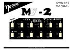
Definition:
Auxiliary functions: ENGL amplifiers are equipped with features that can be activated remotely such as channel selection.
In this context "auxiliary functions" are features other than channel selection that can switched via the MIDI Interface Port
(e.g. Master A/B, Rough/Smooth, Reverb, etc.).
1 Channel 1, Clean
2 Channel 2, Crunch
3 Channel 3, Soft Lead
4 Channel 4, Heavy Lead
5 Function 1, Master A/B
6 Function 1 Selector
7 Custom Footswitch Port
8 Function 2 Selector
9 Function 2, Reverb
The amp is switched to Channel 1, Clean Channel when you press this button. The red LED located above
the button illuminates to indicate the Clean channel is active. This channel is also the default, i.e. it is
activated automatically when you power the amp up.
When you press this button, the amp switches to Channel 2, Crunch Channel, which is equivalent to the
Crunch 1 channel in all amp heads. The red LED located above the button illuminates to indicate the
Crunch (Crunch1) channel is active.
When you press this button, the amp switches to Channel 3, Soft Lead Channel, which is equivalent to the
Crunch2 channel in all amp heads. The red LED located above the button illuminates to indicate the
Soft Lead (Crunch2) channel is active.
When you press this button, the amp switches to Channel 4, Heavy Lead Channel, which is equivalent to
the Lead channel in all amp heads. The red LED located above the button illuminates to indicate the
Lead channel is active.
This button activates one or several of the amp's auxiliary functions, depending on the code switch (6)
setting. The factory preset for the code switch is "1-On," which for the Combo Model E360, switches
Master A and Master B. The red LED located above the button illuminates to indicate Master B is active,
or that function you have defined via the code switch (6) is active.
The code switches of this coding group (located under the cover panel) enable you to assign one or
several auxiliary functions to the Footswitch's Function 1 Selector button. Refer to Table 1 for details on
which code switch is responsible for which auxiliary function. Code Switch 7 in this group is assigned the
special function "MIDI MODE LED Active", In the On position, the MIDI Mode LED at the amp illuminates.
You can, if you so desire, use this LED to indicate that the Footswitch is connected.
25-pin Sub-D port located on the side panel of the footswitch. Plug the connector cable from the amp
to this port.
IMPORTANT! CAUTION!
Never connect either of the two ports at the amp or footswitch to an external device such as a
computer or printer, etc. If you do, you may damage the device and possibly the amp and footswitch.
The code switches of this coding group (located under the cover panel) enable you to assign one or
several auxiliary functions to the Footswitch's Function 2 Selector button. Refer to Table 1 for details on
which code switch is responsible for which auxiliary function. The special functions of code switch 7 are
explained on Page 2, in the section entitled "Function 2 Selector: special function Code Switch 7".
This button activates one or several of the amp's auxiliary functions, depending on the code switch (8)
setting. The factory preset for the code switch is "2-On," which for the Combo Model E360, switches
on/off the Reverb. The red LED located above the button illuminates to indicate Reverb is active,
or that function you have defined via the code switch (8) is active.
E1
Operating Instructions
Custom Footswitch Z-10:
Function 2 Selector: special function code switch 7
In the OFF position: Channel and auxiliary functions can be switched at the amp as well as via footswitch,
provided the function buttons at the amp are in the ON position (depressed). This setting is essential for amps
that feature several auxiliary functions, such as Model E610 and E660, to ensure that these auxiliary functions are not blocked.
Table 3 illustrates an application option for the SAVAGE special edition (Model E660).
NOTE: The function button at the amp for the feature you went to switch via the Z-10 must be in the ON position (depressed),
otherwise you cannot activate the function via footswitch!
In the ON position: All function buttons at the amp are blocked. The channel and auxiliary functions can be activated and
switched via footswtich only. This option should be used for amps such as Model E360 that feature two auxiliary functions.
This is also a practical application for the SAVAGE 120, when you want to set up the following configuration:
Master A/B assigned to the Function 1 button (5) and both Rough/Smooth and Presence A/B assigned to the
Function 2 button (9). The code switch settings for this configuration are depicted in Table 2.
NOTE: To avoid malfunctions, identical code switch numbers in the code switch groups (6) and (8) should never be set to the
ON position! In other words, both Switch 1 of Group (6) and Switch 1 of Group (8) may not be set to ON, Switch 2, Group (6)
and Switch 2, Group (8) must have different settings, and so forth. The only exception to this rule is Code Switch 7.
NOTE: Once you have configured the code switches,
replace the covers to prevent dust and debris from entering the footswitch chassis.
Any foreign matter in the switches can cause malfunctions.
The covers are easy to remove. First remove the front panel
and then simply spread the four detent latches and pull the cover off.
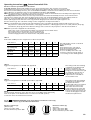
Table 1:
Code switch auxilliary function assignments for diverse amp models
code switch =>
1
2
3
4
5
6
Sovereign 100*
Typ E360 (E362)
Master
A/B
Reverb
On/Off
-
-
-
-
SAVAGE 120
Typ E610
Rough/
Smooth
Master
A/B
Presence
A/B
-
-
SAVAGE special edition
Typ E660
Rough/
Smooth
Master
A/B
Presence Reverb Speaker Triode
A/B
On/Off
A/B
Pentode
model:
-
This table applies for both code switch
groups (6) and (8)
NOTE:
Code switches in the code switch
group (6) and (8) bearing identical
numbers should never both
be set to the ON position! The only
exception of this rule is Code Switch 7.
*: For settings see the drawing below!
Table 2:
Suggested configuration for SAVAGE 120, Type E610:
code switch =>
1
2
3
4
5
6
7
Function 1-Selector (6):
Off
On
Off
Off
Off
Off
Off/On
Function 2-Selector (8):
On
Off
On
Off
Off
Off
On
Table 3:
Suggested configuration for SAVAGE special edition, Type E660:
code switch =>
1
2
3
Function 1-Selector (6):
Off
On
Off
Function 2-Selector (8):
On
Off
On
4
5
6
7
Off
On
On
Off/On
Off
Off
Off
Off
NOTE:
For this example, all buttons at the amp must be set to the ON position (depressed),
with the exception of the Reverb button. If a button is in the OFF position,
its function cannot be activated via footswitch.
This setting results the following
configuration: The Master A/B
feature is assigned to the
Function 1 button (5) and both
Rough/Smooth and Presence A/B
are assigned to the Function 2
button (9). All functions can
only be remote controlled via
the Footswitch Z-10.
This setting results the following
configuration: The Master A/B,
Triode/Petode and the
Speaker A/B feature are assigned
to the Function 1 button (5);
that means this functions are
being switched at the same time
when you depress the Function1
button. The function 2 button (9)
controls the Rough/Smooth and
the Presence A/B function.
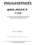
For the
SOVEREIGN 100 (E360) set the Code switches at Function 1 Selector (6)
and Function 2 Selector (8) as described and drawn here:
2
ON
OFF
3 4 5 6
7
Function 1
Selector
1
2 3 4 5 6 7
ON
OFF
1
Function 1 Selector (6):
("Master A/B")
switch 1 in position "ON";
all other switches in position "OFF"
Function 2
Selector
Function 2 Selector (8):
("Reverb")
switch 2 in position "ON";
switch 7 in position "ON";
all other switches in position "OFF"
E2