1
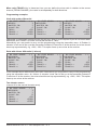
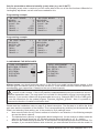
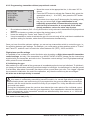
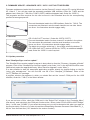
Operating Instructions 33575 33576 33577 1. 2. 2.1. 2.1.1 2.2. 2.3 3. 3.1. 3.2. 3.3. 3.4 4. 4.1. 4.2. 4.2.1 4.2.2 4.3 5. 6. Receiver GR-12 SH +3xG HoTT Receiver GR-12 +3xG HoTT Receiver GR-12 +3xG+3A Vario Notes......................................................................................................................02 Functions...............................................................................................................04 Binding.........................................................................................................04 Binding multiple receivers...................................................................................04 Fail-Safe function...............................................................................................04 Range-checking...........................................................................................05 Receiver..................................................................................................................06 Connections..................................................................................................07 Receiver set-up menu........................................................................................08 Free mixers.......................................................................................................08 Assigning the gyro axes......................................................................................10 Programming the gyro settings...............................................................................12 Programming PID correction..............................................................................12 Programming the factors....................................................................................13 Programming, transmitter with proportional controls............................................13 Programming, transmitter without proportional controls.......................................14 Initialising the gyro.....................................................................................................14 Firmware update..............................................................................................16 Conformity declaration / Guarantee / Manufacturer’s declaration / Disposal..17 Manual V1.0 Revision: Januar 2013 GRAUPNER/SJ GmbH – Postfach 1242 – 73230 Kirchheim/Teck – www.graupner.de MANY THANKS for deciding to purchase the Graupner/SJ HoTT 2.4 system. Please read right through these operating instructions before you attempt to install and operate the Graupner HoTT 2.4 system. • • • • • • • • The receiver stabilises the model aircraft in difficult, windy conditions, acting on a maximum of three axes Proportional gyro suppression for natural flying characteristics Excellent stabilisation for smooth, accurate manoeuvres The triple-axis gyro endows even very demanding aerobatic models with docile flying characteristics, and greatly simplifies aerobatics Aerobatic manoeuvres can be flown much more accurately Simple gyro assignment procedure Facility to adjust parameters using HoTT telemetry Altitude sensor for vario and altimeter function (Order No. 33577) 1. APPROVED USAGE The receiver is intended exclusively for use in radio-controlled models. Any other usage is prohibited, and may result in damage to the receiver or model, and serious personal injury. We grant no guarantee and accept no liability for any type of use outside the stipulated range. Not suitable for children under fourteen years. This receiver is not a toy! The receiver is also equipped with a telemetry function which is only available in combination with a Graupner/SJ HoTT 2.4 system. If you do not own a Graupner/SJ HoTT 2.4 system, the receiver will not work. Please start by reading through the whole instructions before you attempt to install and operate the receiver. These operating instructions are an integral part of the product. They contain important notes on operating and handling the receiver. For this reason please store the operating instructions in a safe place, and pass them on to the new owner if you ever dispose of the product. Failure to observe the operating instructions and safety notes invalidates the guarantee. Here at Graupner we are constantly working on the further development of all our products; for this reason we are obliged to reserve the right to introduce changes to the set contents in form, technology and features. Please understand that we will not countenance claims resulting from information and illustrations in these operating instructions. Please store the operating instructions in a safe place for future reference! 1.1 SAFETY NOTES KEY TO THE SYMBOLS Caution! This symbol alerts you to prohibited actions which must be observed at all times. Any failure to observe the prohibited action indicated in this way may prevent the equipment working, and endanger the safety of the operator. Caution! This symbol alerts you to information which must be observed at all times. Any failure to observe the information indicated in this way may prevent the equipment working properly, and endanger the safety of the operator. This symbol indicates information which should always be observed in order to ensure that the equipment operates reliably. 2 Manual Receiver GR-12+ 3xG Graupner HoTT 2. 4 SAFETY NOTES Warning! The receiver must never be operated under the influence of medication, alcohol, drugs etc. Caution! Any deviation from the instructions may have an adverse effect on the function and operational security of the receiver, and must be avoided under all circumstances. Caution! The operator bears full responsibility for using the receiver. The only way to guard against personal injury and property damage is to handle the equipment carefully and use it exactly as recommended. Caution! Not suitable for children under fourteen years. Caution! Protect the receiver from dust, soiling, damp and foreign bodies. Never subject the receiver to excessive vibration, heat or cold. Caution! During the programming process you must bear in mind that an internal combustion engine or electric motor could unexpectedly burst into life at any time. Caution! Avoid subjecting the receiver to shocks and pressure. Check the receiver regularly for damage to the case and cables. Do not re-use a receiver which is damaged or has become wet, even after it has dried out again. Caution! When deploying the cables ensure that they are not under tension, not tightly bent (kinked) or fractured. Avoid sharp edges which could damage cable insulation. Caution! Ensure that all plug-in connections are firmly seated. Do not pull on the wires when disconnecting plugs and sockets. Caution! The receiver must not make physical contact with the model’s fuselage, hull or chassis, as this would allow motor vibration and landing shocks to be transferred directly to it. Caution! It is not permissible to carry out modifications of any kind to the receiver. Any changes invalidate product approval, and you forfeit any insurance protection. Caution! Ensure that the equipment is working correctly and at full range before every flight. Check the state of the batteries at regular intervals. Note! Ensure that all your HoTT components are loaded with the current version of the software at all times. Note! Safety is no accident, and radio-controlled models are not playthings! Manual Receiver GR-12+ 3xG Graupner HoTT 2. 4 3 1.2 GENERAL NOTES • The receiver’s integral gyros are very fast, high-resolution components. This means that you should always use high-speed digital servos wherever possible, so that the gyro’s corrective signals are converted directly and accurately into servo movement; this helps to prevent the model oscillating. • Keep all servo extension leads as short as possible. • When switching on or adjusting the radio control system, it is essential to keep the transmitter aerial at least 15 cm from the receiver aerial(s). If the transmitter aerial is too close to the receiver aerials, the receiver will be swamped and the red LED on the receiver will light up. The transmitter responds with a flashing red LED and repeated beeps at approximately one-second intervals, i.e. the radio control system reverts to fail-safe mode. If this should happen, increase the distance until the audible warning ceases, and the blue transmitter LED lights up constantly once more. The red LED on the receiver should now be off. 2. FUNCTIONS 2.1. Binding The Graupner/SJ HoTT 2.4 receiver must be “bound” to “its” Graupner/SJ HoTT 2.4 RF module (transmitter) before a radio link can be created between them; this process is known as “binding”. Binding is only necessary once for each combination of receiver / RF module, so the binding procedure described below only needs to be repeated if you add more receivers. However, binding can be repeated at any time if you wish; for example, if you switch transmitters. This is the procedure in detail: • Binding is only possible if the receiver has not been linked with a bound transmitter since being switched on (red LED lights); press the SET button to set the receiver to BIND mode. • If you have already bound a receiver to the transmitter, and wish to bind the receiver to a new model memory, this is the procedure: • Switch the transmitter’s RF section off in the “Basic model settings” menu. • Switch the receiver on, and press the SET button to set it to Bind mode. • Initiate binding in the transmitter’s “Basic model settings” menu. • The red receiver LED should go out within about ten seconds. If it does, the binding process has been completed successfully. • Your transmitter / receiver combination is now ready for use. • However, if the red LED continues to glow, then the binding process has failed. If this should happen, repeat the whole procedure. 2.1.1. Binding multiple receivers per model If necessary it is also possible to bind more than one receiver to a particular model. First bind each receiver individually as described earlier. When the system is actually in use, the receiver which was last bound acts as the Master unit, and any telemetry sensors installed in the model must be connected to this receiver, as only the Master receiver transmits the data to the ground using the downlink channel. The second - and any other - receivers operate in Slave mode, in parallel with the Master receiver, with the downlink channel switched off. The channel mapping function of HoTT telemetry also allows the control functions to be divided up amongst multiple receivers, or alternatively the same control function to be assigned to multiple receiver outputs. For example, this is useful if you wish to actuate each aileron with two servos instead of just one. 2.2. Fail-Safe function In the receiver’s default state, all connected servos remain in their last valid position (“Hold” mode) if a fail-safe situation should arise. In fail-safe mode the red LED on the receiver lights up, and the transmitter generates an audible alert by beeping at a rate of around one per second. You can exploit the safety potential of this option by at least setting the throttle position (for internalcombustion powered models) to Idle, or the motor function (electric-powered models) to “Stop”, or “Hold” for a model helicopter, if a fail-safe event should occur. These settings ensure that the model is less likely to fly out of control if interference should occur, thereby helping to avoid property damage or even 4 Manual Receiver GR-12+ 3xG Graupner HoTT 2. 4 personal injury. Read the operating instructions supplied with your radio control system for more details. The gyro system remains active in a fail-safe situation. 2.3 Range-checking The range of your Graupner/SJ HoTT 2.4 system can be checked as described in the following instructions. We recommend that you ask a friend to help you with the procedure. Ideally the receiver should already be bound to the transmitter. Install it in the model in its final position. • Switch the radio control system on, and wait until the red LED on the receiver goes out. The servo movements can now be observed. • Place the model on a flat surface (pavement, close-mown grass, earth), and ensure that the receiver aerials are at least 15 cm above the ground. It may be necessary to pack up the model to achieve this for the period of the range-check. • Hold the transmitter away from your body at hip-level. Don’t point the transmitter aerial straight at the model; instead rotate or angle the aerial tip in such a way that it is vertical when you operate the transmitter controls. • Select range-check mode, as described in the transmitter instructions. • Walk away from the model, moving the transmitter sticks. If you detect an interruption in the radio link at any time within a distance of about 50 m, see if you can reproduce the problem. • If your model is fitted with a motor or engine, switch it on or start it, so that you can check effective range when potential interference is present. • Walk further away from the model to the point where full control is no longer possible. • At this point you should manually switch off range-check mode. The model should now respond to the controls again. If this is not 100% the case, do not use the system. Contact the Graupner/SJ Service Centre in your locality and ask their advice. We recommend that you carry out a range-check before every flight, simulating all the servo movements which occur in flight. To guarantee reliable model operation, radio range must always be at least 50 m on the ground. 2.4 INSTALLATION IN THE MODEL The gyro-receiver must be installed “square” relative to the model, i.e. at right-angles to the aircraft’s longitudinal axis, otherwise the gyros will be unable to function as intended (Order No. 33577 must also be horizontal relative to the fuselage centreline to allow the accelerometer to work correctly). Also required for Order No. 33577 OK Manual Receiver GR-12+ 3xG Graupner HoTT 2. 4 OK 5 3. RECEIVER 3.1 Connections Connect the servos to the row of sockets on one end of the receiver. The connectors are polarised: note the small chamfers on one side. Never use force - the connectors should engage easily. The polarity is also printed on the receiver; the negative wire (-) is brown, the positive (+) red and the signal orange. The servo sockets of Graupner/SJ HoTT 2.4 receivers are numbered sequentially. The socket for channel 6 can also be programmed to deliver a (digital) sum signal (see section 3.2: Receiver set-up). I²C (Inter-Integrated Circuit) - socket currently not active; for servicing purposes only! Power supply OK The receiver does not feature specific sockets for connecting the battery. We recommend that you connect the power supply to the socket(s) close to the servos already connected to the receiver. If you wish to connect multiple separate batteries, the batteries must be of the same nominal voltage and capacity. Never connect batteries of different type, or packs of greatly differing states of charge, as this can cause effects similar to a short-circuit. If you encounter this problem, we recommend the use of a voltage stabiliser unit (e.g. PRX-5A receiver power supply, Order No. 4136) between the batteries and the receiver. Telemetry The optional telemetry sensors are connected to the socket marked “T” (Telemetry). Alternatively the receiver can monitor a voltage up to max. 25.5 V DC via this socket, which is also used to update the receiver’s firmware with the help of the USB interface. NOTE: you can either connect this socket to a servo or a telemetry sensor or the battery to be monitored; the receiver must be set up accordingly. Please see the following section for further details. WARNING: never connect a battery with a voltage higher than 8.4 V DC directly to the receiver, as this would instantly ruin the unit and any servos or other accessories connected to it. Caution! If you activate voltage measurement, the receiver can monitor a voltage of up to max. 25.5 V DC via this input, but only if the circuit shown below is used. Never connect a battery to the Telemetry socket without this circuit! max. 25,5 V DC ← Channel 5 6 Manual Receiver GR-12+ 3xG Graupner HoTT 2. 4 PROGRAMMING THE GENERAL RECEIVER SETTINGS: The receiver can be programmed using a suitable HoTT transmitter or the SMART-BOX (Order No. 33700). 3.2 RECEIVER SET-UP MENU RECEIVER 1.0 < > The receiver set-up menu appears in the “Telemetry” menu >ALARM VOLT: 3.8V under SETTINGS / DISPLAYS; alternatively - if you are using a ALARM TEMP: 70°C SMART-BOX - under SETTING & DATAVIEW. The method of max altitude: 125m accessing this menu is described in the operating instructions >Period: 10ms supplied with your transmitter or the Smart-Box. >SUMD at K6: No K5: SERVO LANGUAGE: english Display Explanation Settings RECEIVER 1.0 1.0 indicates the version of the receiver’s firmware - ALARM VOLT. Alarm threshold for the receiver’s low voltage warning (or voltage measurement) 2.5 - 24.0 V Default setting: 3.8 V ALARM TEMP. Receiver overheating warning 50 - 80° C Default setting: +70° C Max. height Order No. 33577 only, with integral vario: maximum altitude 0 - 2500 m in 25 m increments ZYKLUS Cycle time (frame rate) in ms 10 / 20 ms SUMD an K6 Digital sum signal at channel 6 Yes / No K5 Use of channel 5: servo, telemetry sensor or voltage measurement Servo, Sensor, Spannung Werkseinstellung: Servo LANGUAGE Select menu language German, English, French, Italian or Spanish Low-voltage warning (ALARM VOLT): if the receiver voltage or the external voltage connected to channel 5 falls below the set value, a low-voltage warning is generated by the transmitter’s RF module in the form of the “general alarm tone”: a regular beeping at a rate of about one per second; alternatively the speech output message “Receiver voltage”. Temperature warning (ALARM TEMP): if the receiver temperature exceeds the set temperature threshold, a warning is generated by the transmitter’s RF module in the form of the “general alarm tone”: a regular beeping at a rate of about one per second; alternatively the speech output message “Receiver temperature”. Maximum height (Max. height) - Order No. 33577 with integral vario only: at this point you can enter a maximum altitude, at which an alarm is triggered, either via the transmitter’s RF module in the form of the “general alarm tone”: a regular beeping at a rate of about one per second; alternatively the speech output message “Height”. Note: the model’s actual height is adopted as zero when the receiver is switched on; the indicated height is therefore the altitude relative to the launch point. Cycle time (CYCLE): if your system is used exclusively with digital servos, you can set a cycle time (frame rate) of 10 ms at this point. If your system includes some or all analogue servos, you should always select 20 ms, as many analogue servos cannot process the higher frame rate, and may respond Manual Receiver GR-12+ 3xG Graupner HoTT 2. 4 7 by “jittering” or “growling”. HoTT sum signal (SUMD): if you activate the digital sum signal at channel 6, a sum signal containing eight channels is present at this socket, instead of a servo signal. The HoTT receiver configured as SUMD constantly generates a digital sum signal from 8 control signals from the transmitter and makes this signal available at the appropriate servo socket, which is receiver-specific. At the time these instructions were revised, this type of signal is used by several of the latest electronic developments in the area of flybarless systems, heavy-duty airborne power supplies, etc. WARNING: if you wish to use this facility, it is essential to observe the set-up information supplied with the devices connected to the receiver, otherwise there is a risk that your model may be uncontrollable. Channel 5 (Ch5): channel output 5 can be used to control a servo, as a telemetry socket or for voltage monitoring. If you activate voltage monitoring, the receiver can measure a voltage of up to max. 25.5 V DC via this input (instead of a servo or telemetry sensor) using the circuit described in section 3.1. The monitored voltage is then displayed on the screen instead of the receiver voltage. This makes it possible, for example, to monitor the flight battery directly, without the need for an additional voltage sensor. If channel 5 is set to ‘sensor’ or ‘voltage’ instead of servo, the channel 5 signal is automatically available at channel 6. This change will not take effect until turning on / off the receiver. 3.3 FreE MIXERS Important note: If you wish to use the gyros, RX FREE MIXER < > you must always set the tail type to ‘normal’ in the >MIXER: 1 transmitter’s model type menu. If your model is a delta, MASTER CH: 1 features a V-tail, or has two elevator servos, you must use the SLAVE CH: 6 receiver mixer - not the transmitter mixer - to control these >TRIM: +0% control surfaces, since the gyro stabilisation system will >TRAVEL-: +100% have no effect on these servos otherwise. The four receiver TRAVEL+: +100% mixers work ‘downstream’ of the gyros. If you have already programmed mixer functions in the “Wing mixers” or “Free mixers” menu of your HoTT transmitter, you must ensure that those mixers do not overlap with those available in this menu! Screen Display Key Settings MIXER Mixer select 1, 2....4 FROM CHANNEL Signal source / source channel 0,1,2,...6 TO CHANNEL Target channel 0,1,2,...6 TRIM Trim position in % -15 - + 15% TRAVEL- Travel limit at % Servo travel -150 bis +150% TRAVEL+ Travel limit at % Servo travel -150 bis +150% MIXER: up to four mixers can be programmed simultaneously. You can switch between Mixer 1, Mixer 2, … and mixer 4 in the “Mixer” line. The following settings only affect the mixer selected in this line. FROM CHANNEL: the signal present at the signal source (or source channel) is mixed in to the target channel (TO CHANNEL) to an extent which can be set by the user. The method of setting up the values is analogous to the “Free mixers” menu in HoTT transmitters. TO CHANNEL: part of the source channel signal (FROM CHANNEL) is mixed into the target channel (TO CHANNEL). The mixer ratio is determined by the percentage values entered in the “TRAVEL-“ and “TRAVEL+” lines. Select “0” if you do not require the mixer. 8 Manual Receiver GR-12+ 3xG Graupner HoTT 2. 4 Mixer ratio (TRAVEL-/+): in these two lines you can define the mixer ratio in relation to the source channel (FROM CHANNEL); the value is set separately for both directions. Programming examples: V-tail with rudder differential RX FREE MIXER < > RX FREE MIXER < > RX FREE MIXER < > >MIXER: 1 >MISCHER: 2 >MIXER: 3 MASTER CH: 3 MASTER CH: 4 MASTER CH: 4 SLAVE CH: SLAVE CH: SLAVE CH: 4 3 4 >TRIM: +0% >TRIM: +0% >TRIM: +0% >TRAVEL-: +100% >TRAVEL-: -60% >TRAVEL-: +100% TRAVEL+: TRAVEL+: TRAVEL+: +100% +100% +60% Differential is not normally necessary with this tail type. Mixer 3 is not required if you do not need rudder differential, and TRAVEL- for mixer 2 must then be set to -100%. Alternatively you may prefer to carry out the programming using the transmitter menu. A ‘Rudder elevator’ mixer can be set up at the transmitter instead of ‘Free mixer 3’ at the receiver; the mixer should be set up asymmetrically, e.g. +30%, -30%. This option frees up one mixer at the receiver. Delta with aileron differential (1 aileron) RX FREE MIXER < > RX FREE MIXER < > RX FREE MIXER < > >MISCHER: 1 >MISCHER: 2 >MISCHER: 3 MASTER CH: 2 MASTER CH: 3 MASTER CH: 2 SLAVE CH: SLAVE CH: SLAVE CH: 3 2 2 >TRIM: +0% >TRIM: +0% >TRIM: +0% >TRAVEL-: +100% >TRAVEL-: -100% >TRAVEL-: +60% TRAVEL+: TRAVEL+: TRAVEL+: +60% -100% +100% In this example aileron differential is set to 40%. Alternatively you may prefer to carry out the programming using the transmitter menu. An ‘Aileron elevator’ mixer can be set up at the transmitter instead of ‘Free mixer 3’ at the receiver; the mixer should be set up asymmetrically, e.g. +30%, -30%. This option frees up one mixer at the receiver. Two elevator servos (channel 6 for the second elevator servo) RX FREE MIXER < > >MISCHER: 1 MASTER CH: 3 SLAVE CH: 8 >TRIM: +0% >TRAVEL-: +100% TRAVEL+: +100% Manual Receiver GR-12 + 3xG Graupner HoTT 2. 4 9 Only for transmitters without a butterfly (crow) mixer (e.g. mx-10 HoTT): If a butterfly (crow) mixer is required, you will not be able to use one of the two functions ‘differential’ or ‘landing flap’ adjustment, as two mixers are needed for this. Programming example: RX FREE MIXER < > RX FREE MIXER < > >MIXER: 1 >MISCHER: 2 MASTER CH: 1 MASTER CH: 1 SLAVE CH: SLAVE CH: 2 5 >TRIM: +0% >TRIM: +0% >TRAVEL-: +100% >TRAVEL-: -100% TRAVEL+: TRAVEL+: +100% -100% Programming example: RX FREE MIXER < > RX FREE MIXER < > >MISCHER: 1 >MISCHER: 2 MASTER CH: 1 MASTER CH: 1 SLAVE CH: SLAVE CH: 2 3 >TRIM: +0% >TRIM: +0% >TRAVEL-: +100% >TRAVEL-: -100% TRAVEL+: TRAVEL+: +100% -100% 3.4 ASSIGNING THE GYRO AXES GYRO ASSIGNMENT >AILERON SERVOS: DO SETUP: AILERON: ELEVATOR: RUDDER: < 2 YES +2 +0 -0 GYRO ASSIGNMENT >AILERON SERVOS: DO SETUP: AILERON: >ELEVATOR: >RUDDER: < 2 NO +2 +1 -3 Aileron servos: you should enter the value 2 in this line if your model has two aileron servos; in this case the gyro for channel (servo) 2 also acts on servo 5. If the ailerons are also used as flaperons or speedbrakes, gyro suppression is based on the sum of both channels. CAUTION: the servo reverse setting must be the same for both aileron servos, i.e. either both ‘normal’ or both ‘reverse’. If this is not possible, on no account should you reverse one servo in the transmitter menu. The only option is to re-install it in the model by turning it round physically. However, if your model is fitted with programmable servos (e.g. Graupner DES, HVS or HBS types - see the instructions for the update program ‘Firmware_Upgrade_grStudio - then it is possible to reverse the direction of rotation at the servo itself. Please read the installation notes on page 5 of these instructions. The first step is to define the three gyro axes and the orientation of the receiver. This is accomplished by switching on the transmitter and model, and selecting ‘New setting: yes’ in the receiver’s ‘Gyro settings’ menu. • Now move the stick for any control surface to full travel in one direction; in the following example we use the aileron channel. • The detected axis (aileron) is highlighted (black background). (In the receiver’s default state the value for all axes is shown as ‘+0’; the axes can also be set manually to ‘+0’. 0 = inaktiv) • Now turn the model through at least 45° in the direction corresponding to the stick movement. For example, if you moved the aileron stick to the left, you must simulate a left turn with the model 10 Manual Receiver GR-12+ 3xG Graupner HoTT 2. 4 • • • move the left wing down through at least 45°. This process defines the one axis and direction; now you must repeat the procedure for the other two axes. The gyro axis 1, 2 or 3 is now displayed in the ‘Aileron / Elevator / Rudder’ display; a negative prefix will appear if servo reverse is activated. Once all three axes are defined, the display automatically reverts to ‘New setting: no’. WARNING: once you have completed this procedure, it is absolutely essential to check that all the gyros are working in the correct direction. This is accomplished by moving the model around all three axes in turn, and checking the control surface deflections - see diagrams below. You must not fly the model before doing this: crash hazard! ELEVATOR Model movement Control surface response (seen from the tail) Model movement Control surface response (seen from the tail) RUDDER AILERON Model movement Control surface response (seen from the tail) Manual Receiver GR-12+ 3xG Graupner HoTT 2. 4 11 4. PROGRAMMING THE GYRO SETTINGS: PID (Proportional Integral Differential) correction The stabilising effect of the gyro sensors is based fundamentally on three parameters: P factor: defines proportional correction P = proportional: if the intended value is not the same as the actual value, then the difference is fed proportionally into the corrective signal; in simple terms, the input value (e) is multiplied by a fixed value: u(t) = Kp*e(t). Kp is termed the amplification value. The output value is therefore proportional to the gyro’s input value. Proportional correction cannot occur until a deviation from the intended value is present; if the deviation is 0, then the product is also zero. If the amplification value is set too high, the P factor causes the model to oscillate and become unstable. I factor: integral correction (not currently implemented) D factor: defines differential correction D = differential: in this case the corrective output value is affected by the rate of change of the input value, i.e. the faster the model tilts around the axis, the more pronounced the corrective response of the gyro. If the model changes attitude very gently, then the D factor causes hardly any corrective action. It also makes absolutely no difference how far the model has already changed attitude; the crucial value is only the speed or rate of the movement. The rate of change is again multiplied by a factor (as with P correction) to produce the output value. For this reason pure D correction is not used; it must always be employed in combination with P correction. 4.1 Programming PID correction - Gyro settings display: CAUTION: before you start entering settings for a new model, it is essential to select the number of aileron servos in the Aileron servos menu point, and to define the gyro axes and orientation in the New settings menu point. Aileron / Elevator / Rudder: shows the programmable P factors for the corresponding control surface. Note: the gyro axes must first be defined under New settings (see section 3.4). If you wish to disable the gyro, enter the value OFF in the appropriate control function. P factor: The P factor should always be set first, followed by the D factor (adjustment range in each case 0 to 10). A general rule is that the larger the control surface, the smaller the P factor required. Start with a factor of 2 (default setting), and do not exceed 4 - 5 as maximum value for the normal flight phase, 2 - 3 for speed, 3 - 6 for landing; the maximum value of 10 should be reserved for torque-rolls only. WARNING: if you program separate flight phases, it is essential to select the appropriate flight phase when the model is in the air, as inappropriate gyro settings may cause the control surfaces to oscillate, possibly resulting in the loss of the model! Note: the higher the model’s speed, the more quickly oscillation may set in. D factor: for a given P factor setting, the model’s tendency to oscillate can be reduced by setting a lower D factor. However, if you select a lower setting for the P factor, then you may be able to set a higher D factor value before the onset of control surface oscillation. The gyro effect can be optimised by finetuning the D factor. 12 Manual Receiver GR-12+ 3xG Graupner HoTT 2. 4 Note: the standard P and D values should cause the gyros to correct the model’s attitude quickly when it is upset by an outside influence, without causing oscillation, but in practice the optimum values for a particular model can only be found by flight-testing. If the model displays little or no automatic stabilisation with the default settings, the value should be raised; on the other hand, if the model oscillates (wave-like movements in flight), the value should be reduced. If your transmitter has spare proportional controls, you can use them to adjust the values while the model is flying. Some transmitters allow the corrective factors to be altered during a flight using the proportional controls, whereas others allow fixed values only. 4.2 Programming the factors 4.2.1 Programming, transmitter with proportional controls If your HoTT transmitter is equipped with proportional controls, it is also possible to adjust the P and D factors for each axis during a flight: what you might call ‘flying the settings’. You need to assign proportional controls (e.g. the sliders on the mc-20) to any channel in the range 5 to 16 (in this example channel 9); now you can alter the P factor (and the D factor) using these controls. In each case the current values are shown in brackets. Procedure, using the ailerons as an example: • Move the cursor to the appropriate line, in this case “Ail” for aileron. • Press the SET button to activate the Channel field. • Select the appropriate channel, and save the setting with pressing the SET button again • move the corresponding proportional control to alter the factor (adjustment range 0 - 10; 0 means no gyro correction for that axis). • You can also adopt this factor directly by pressing the left button < or the right button >. This frees up the channel previously occupied by the proportional control, so that it can be used for some other purpose, e.g. for elevator or rudder. Move on to elevator and / or rudder, and select the channel and factor (you can either select the same channel, in order to alter all the axes simultaneously, or different channels, allowing you to program the axes individually). Move the cursor to the Factor line, where you can also change the P factor for aileron, elevator and rudder with priority (adjustment range up to 200%). Move the cursor to the D factor line, where you can alter the D factor for aileron, elevator and rudder with priority using a proportional control (adjustment range up to 200%; channel value -100% equates to a factor of 0%, channel value 0% equates to 100%, and +100% equates to 200%). This makes it a very easy matter to match the gyro’s corrective effect to the model’s airspeed. In particular, higher gyro gain can be used for the landing approach - without the need to switch flight phases. Now test-fly your model and fine-tune the values one by one until your preferred stabilising effect is achieved without the model oscillating. It may be sensible or easier to activate the gyro for one axis only at first, and then to establish the optimum setting for that axis, rather than for several axes simultaneously. GYRO SETTINGS < > (2)K9 >AILERON: (3)K8 >ELEVATOR: 6 >RUDDER: (44%)K10 COEFF.: (140%)K11 COEFF. D: • • • • • Manual Receiver GR-12+ 3xG Graupner HoTT 2.4 13 4.2.2. Programming, transmitter without proportional controls • Move the cursor to the appropriate line, in this case “Ail” for aileron. • Press the SET button to activate the Channel field, select the appropriate value (1 - 10 of OFF), then press the SET button to save it. • First select a low value (see P factor section for starting points) and carry out a test-flight. If gyro stabilisation is not sufficiently pronounced, increase the value step by step until the level of correction is as required; if the model already oscillates, reduce the value step by step. Do not select a channel (Ch5 - Ch16); this function is only relevant to transmitters with proportional controls. Move on to elevator or rudder and select the desired value (or OFF). Leave the settings for “Factor” and “Factor D” at OFF. It may be sensible or easier to activate the gyro for one axis only at first, and then to establish the optimum setting for that axis, rather than for several axes simultaneously. GYRO SETTINGS >AILERON: >ELEVATOR: >RUDDER: COEFF.: COEFF. D: • • • • < > 2 4 6 Aus Aus Once you have found the optimum settings, you can set up a transmitter switch to control the gyro, i.e. for switching between gain settings. For example, you could assign a three-position switch to “Factor” and “Factor D”, and then use it to switch the values between 0% (OFF), 100% and 200%. Flight phase specific settings It is possible to use a channel to control the factor value by setting up flight phase specific transmitter control settings, but only if the transmitter is an MX20 / MC20 or MC32; please see the instructions supplied with your transmitter and refer to the “Transmitter control settings” and “Flight phase settings” menu points for more information. 4.3 Initialising the gyro After switching on the model of the gyroscope is immediately active but not yet initialized. To initialize it, you keep your model when switching quiet and straight in level flight - the best place it on the flat ground or a flat table. After about 2 seconds, the ailerons move up and down just once. This “wiggle” signaled the successful initialization, the end of the calibration, only then the model may be moved again. All sticks are to be kept strictly in neutral! WARNING: during the initialisation phase the gyro detects the model’s neutral attitude, and for this reason it is absolutely essential to leave the model in its ‘normal flight attitude’ during the activation phase, and avoid moving it! If you neglect this, the gyro may detect an incorrect flight attitude, with the result that the model will not fly as you expect it to. It may be difficult to control, and could even crash! During the initialisation phase the receiver also detects the centre points of the individual control channels; this information is used for gyro suppression. Gyro suppression reduces the stabilising action progressively as the transmitter controls are deflected away from centre; at +/- 100% the gyro is completely disabled. Your model is now ready to fly .. ! 14 Manual Receiver GR-12+ 3xG Graupner HoTT 2. 4 5. FIRMWARE UPDATE - GRAUPNER 33575 / 33576 / 33577 HOTT RECEIVERS Firmware updates are loaded into the receiver via the Channel 5 output, using a PC running Windows XP, Vista or 7. You will also need the separately available USB interface, Order No. 7168.6 and the adapter lead, Order No. 7168.6A or 7168.S (33575: additional adapter lead, Order No. 33565.1). The programs and files required for this can be found in the Download area for the corresponding products at www.graupner.de. Connect the adapter lead to the USB interface, Order No. 7168.6. The connectors are polarised: note the small chamfers on one side. Never use force - the connectors should engage easily. 5.1 Receiver GR-12+3xG HoTT receiver / (Order No. 33576 / 33577): Connect the adapter lead to receiver channel 5 as shown in the picture. The connectors are polarised: note the small chamfers on one side. Never use force - the connectors should engage easily. The black wire must be at the top (-), the orange wire at the bottom (T). GR-12SH+3xG HoTT receiver (Order No. 33575): an additional adapter lead, Order No. 33565.1 is also required. 5.2. Update procedure Start “Slowflyer/Gyro receiver update” The “Slowflyer/Gyro receiver update” program is best called up from the “Firmware_Upgrade_grStudio” program. Click on the “Slowflyer/Gyro receiver update” point under “Link” in the left-hand function menu (alternatively select the appropriate entry “Micro Receiver Upgrade” under “Menu”). It is also possible to start the associated application program directly by double-clicking on the file “micro_gyro_swloader.exe”. You will find this .exe file in the “Graupner_PCSoftware” folder of the “HoTT_Software VX” package. A program window now appears in which you should first set the “correct” COM port for the USB interface, Order No. 7168.6, in the Select window. If you are not sure of this, check the COM port in the “Select Port” window in the “Controller Menu” (see above), and note down the COM port number at the “Silicon Labs CP210x USB to UART Bridge” entry – in this case “COM03” (if you select the wrong port, you will be alerted to this when you read out the receiver data). Click on xx in order to load the corresponding firmware file named “MicroStabi7X_V_ XX.bin” from the hard disc (“XX” stands for the version number.) Manual Receiver GR-12+ 3xG Graupner HoTT 2. 4 15 When the file has loaded, click on Start … … connect the receiver, and switch itAon. B The progress bar shows the transfer proceeding normally. The receiver LED is off during this period, then flashes as soon as the file transfer is complete. Your PC may allow you to carry out a firmware update without a switch and receiver battery. In this case connect the components as shown below: USB lead Interface lead, Order No. 7168.S Interface adapter, Order No. 7168.6 Adapter lead Order No. 23046 for GR-12SC+ receiver, or Order No. 33565.1 for GR-12SH+ receiver Three-core connecting lead, Order No. 33700.1 Please refer to the detailed update instructions in the Download area for the corresponding item at http://www.graupner.de. D 16 Manual Receiver GR-12+ 3xG Graupner HoTT 2. 4 6. Conformity declaration / Guarantee / Manufacturer’s declaration / Disposal Konformitätserklärung gemäß dem Gesetz über Funkanlagen und Telekomunikationsendeinrichtungen (FTEG) und der Richtlinie 1999/5/EG (R&TTE) Declaration of Conformity in accordiance with the Radio and Telecomunikations Terminal Equipment Act (FTEG) and Directive 1999/5/EG (R&TTE) Graupner/SJ GmbH Henriettenstraße 96 D-73230 Kirchheim/Teck erklärt, dass das Produkt: declares that the product GR-12SH +3xG HoTT - No. 33575, GR-12 +3xG HoTT - No. 33576 GR-12 +3xG + 3A + Vario HoTT - No. 33577 GR-18 +3xG + 3A + Vario HoTT - No. 33579 GR-24 PRO +3xG + 3A + 3M HoTT - No. 33583 1 Geräteklasse: Equipment class den grundlegenden Anforderungen des § 3 und den übrigen einschlägigen Bestimmungen des FTEG (Artikel 3 der R&TTE) entspricht. complies with the essential requirements of § 3 and the other relevant provisions of the FTEG (Article 3 of the R&TTE Directive). Angewendete harmonisierte Normen: Harmonised standards applied EN 60950-1:2006+A11: 2009+A1:2010+A12: 2011 Gesundheit und Sicherheit gemäß § 3 (1) 1. (Artikel 3 (1)a)) EN 301 489-1 V1.9.2 EN 301 489-17 V2.1.1 Schutzanforderungen in Bezug auf elektromagnetische Verträglichkeit § 3 (1) 2, Artikel 3 (1) b)) Health and safety requirements pursuant to § 3 (1) 1. (Article 3 (1) a)) Protection requirement concernig electromagnetic compatibility § 3 (1) 2, Artikel 3 (1) b)) EN 300 328 V1.7.1 Maßnahmen zur effizienten Nutzung des Frequenzspektrums § 3 (2) (Artikel 3 (2)) Measures for the efficient use of the radio frequency spectrum § 3 (2) (Article 3 (2)) Kirchheim, 17. April 2013 Ralf Helbing, Geschäftsführer Ralf Helbing, Managing Director Graupner/ SJ GmbH Tel: 07021/722-0 Henriettenstraße 96 Fax: 07021/722-188 Manual Receiver GR-12+ 3xG Graupner HoTT 2. 4 D-73230 Kirchheim/Teck Germany EMail: [email protected] 17 Manufacturer’s declaration Content of the manufacturer’s declaration If material defects or manufacturing faults should arise in a product distributed by us in the Federal Republic of Germany and purchased by a consumer (§ 13 BGB), we, Graupner/SJ GmbH, D-73230 Kirchheim/Teck, Germany, acknowledge the obligation to correct those defects within the limitations described below. The consumer is not entitled to exploit this manufacturer’s declaration if the failure in the usability of the product is due to natural wear, use under competition conditions, incompetent or improper use (including incorrect installation) or external influences. This manufacturer’s declaration does not affect the consumer’s legal or contractual rights regarding defects arising from the purchase contract between the consumer and the vendor (dealer). Extent of the guarantee If a claim is made under guarantee, we undertake at our discretion to repair or replace the defective goods. We will not consider supplementary claims, especially for reimbursement of costs relating to the defect (e.g. installation / removal costs) and compensation for consequent damages unless they are allowed by statute. This does not affect claims based on legal regulations, especially according to product liability law. Guarantee requirements The purchaser is required to make the guarantee claim in writing, and must enclose original proof of purchase (e.g. invoice, receipt, delivery note) and this guarantee card. The purchaser must send the defective goods to us at his own cost, using the address stated below. Graupner/SJ GmbH, Service Department, Henriettenstr.96, D 73230 Kirchheim/Teck, Germany Service Department: tel. [0049] 7021-722130 The purchaser should state the material defect or manufacturing fault, or the symptoms of the fault, in as accurate a manner as possible, so that we can check if our guarantee obligation is applicable. The goods are transported from the consumer to us and from us to the consumer at the risk of the consumer. Duration of validity This declaration only applies to claims made to us during the claim period as stated in this declaration. The claim period is 24 months from the date of purchase of the product by the consumer from a dealer in the Federal Republic of Germany (purchase date). If a defect arises after the end of the claim period, or if the evidence or documents required according to this declaration in order to make the claim valid are not presented until after this period, then the consumer forfeits any rights or claims from this declaration. Limitation by lapse of time If we do not acknowledge the validity of a claim based on this declaration within the claim period, all claims based on this declaration are barred by the statute of limitations after six months from the time of implementation; however, this cannot occur before the end of the claim period. Applicable law This declaration, and the claims, rights and obligations arising from it, are based exclusively on the pertinent German Law, excluding the norms of international private law, and excluding UN retail law. 18 Manual Receiver GR-12+ 3xG Graupner HoTT 2. 4 Wir gewähren auf dieses Erzeugnis eine / This product is / Sur ce produit nous accordons une Garantie von warrantied for garantie de 24 Die Fa.Graupner/SJ GmbH, Henriettenstrasse 96, 73230 Kirchheim/Teck gewährt ab dem Kaufdatum auf dieses Produkt eine Garantie von 24 Monaten. Die Garantie gilt nur für die bereits beim Kauf des Produktes vorhandenen Material- oder Funktionsmängel. Schäden, die auf Abnützung, Überlastung, falsches Zubehör oder unsachgemäße Behandlung zurückzuführen sind, sind von der Garantie ausgeschlossen. Die gesetzlichen Rechte und Gewährleistunsansprüche des Verbrauchers werden durch diese Garantie nicht berührt. Bitte überprüfen Sie vor einer Reklamation oder Rücksendung das Produkt genau auf Mängel, da wir Ihnen bei Mängelfreiheit die entstandenen Unkosten in Rechnung stellen müssen. Graupner/SJ GmbH, Henriettenstrasse 96, 73230 Kirchheim/Teck, Germany guarantees this product for a period of 24 months from date of purchase. The guarantee applies only to such material or operational defects witch are present at the time of purchase of the product. Damage due to wear, overloading, incompetent handling or the use of incorrect accessories is not covered by the guarantee. The user´s legal rights and claims under garantee are not affected by this guarantee. Please check the product carefully for defects before you are make a claim or send the item to us, since we are obliged to make a charge for our cost if the product is found to be free of faults. La société Graupner/SJ GmbH, Henriettenstrasse 96, 73230 Kirchheim/Teck, Allemagne, accorde sur ce produit une garantie de 24 mois à partir de la date d´achat. La garantie prend effet uniquement sur les vices de fonction-nement et de matériel du produit acheté. Les dommages dûs à de l´usure, à de la surcharge, à de mauvais accessoires ou à d´une application inadaptée, sont exclus de la garantie. Cette garantie ne remet pas en cause les droits et prétentions légaux du consommateur. Avant toute réclamation et tout retour du produit, veuillez s.v.p. contrôler et noter exactement les défauts ou vices. Monaten months mois Servicestellen / Service / Service après-vente Belgie/Nederland Jan van Mouwerik Slot de Houvelaan 30 NL 3155 Maasland VT (+31)10 59 13 59 4 Servicehotline (+49) (0)7021/722-130 Montag - Donnerstag 7:30 -11:45 und 12:30 -16:00 Uhr Freitag 9:00 - 13:00 Uhr Luxembourg Kit Flammang 129, route d’Arlon L 8009 Strassen (+35) 23 12 23 2 Ceská Republika/Slovenská Republika RC Service Z. Hnizdil Letecka 666/22 CZ-16100 Praha 6 - Ruzyne (+42) 2 33 31 30 95 Schweiz Graupner Service Schweiz CD-Electronics GmbH Kirchweg 18 CH-5614 Sarmenstorf (+41) 56 66 71 49 1 Espana Anguera Hobbies C/Terrassa 14 E 43206 Reus (Tarragona) (+34) 97 77 55 32 0 UK Graupner Service UK Brunel Drive GB, NEWARK, Nottinghamshire NG242EG (+44) 16 36 61 05 39 Graupner-Zentralservice Graupner/SJ GmbH Henriettenstrasse 96 D-73230 Kirchheim / Teck France Graupner Service France Gérard Altmayer 86, rue St. Antoine F 57601 Forbach-Oeting (+33) 3 87 85 62 12 Italia GiMax Via Manzoni, no. 8 I 25064 Gussago (+39) 30 25 22 73 2 Garantie-Urkunde Warranty certificate / Certificat de garantie 33575 Empfänger GR12 SH +3xG HoTT 33576 Empfänger GR-12 +3xG HoTT 33577 Empfänger GR-12 +3xG+3A+Vario Übergabedatum Date of purchase/delivery Date de remise Name des Käufers Owner´s name Nom de I`acheteur Straße, Wohnort Complete adress Adresse complète Manual Receiver GR-12+ 3xG Graupner HoTT 2. 4 Firmenstempel und Unterschrift des Einzelhändlers Stamp and signature of dealer Cachet et signature du vendeur 19 ENVIRONMENTAL PROTECTION NOTES The presence of this symbol on a product, in the user instructions or the packaging, means that you must not dispose of that item, or the electronic components contained within it, in the ordinary domestic waste when the product comes to the end of its useful life. The correct method of disposal is to take it to your local collection point for recycling electrical and electronic equipment. Individual markings indicate which materials can be recycled and re-used. You can make an important contribution to the protection of our shared environment by re-using the product, recycling the basic materials or re-processing redundant equipment in other ways. Dry cells and rechargeable batteries must be removed from the device and taken separately to a suitable battery disposal centre. In the case of RC models electronic components such as servos, receiver or speed controller must be removed from the product, and taken separately to the appropriate collection point for electrical waste. If you don’t know the location of your nearest disposal centre, please enquire at your local council office. Graupner/SJ GmbH Henriettenstraße 96 D-73230 Kirchheim/Teck Germany www.graupner.de Änderungen sowie Liefermöglichkeiten vorbehalten. Lieferung durch den Fachhandel. Bezugsquellen werden nachgewiesen. Für Druckfehler kann keine Haftung übernommen werden. Specifications and availability subject to change. Supplied through specialist model shops only. We will gladly inform you of your nearest supplier. We accept no liability for printing errors. Sous réserve de modifications et de possibilité de livraison. Livraison uniquement au travers de magasins spécialisés en modélisme. Nous pourrons vous communiquer l’adresse de votre revendeur le plus proche. Nous ne sommes pas responsables d’éventuelles erreurs d’impression. Mai 2013 - DE V1.0 Manual Receiver GR-12+ 3xG Graupner HoTT 2. 4 20