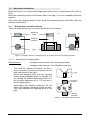
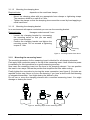
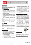
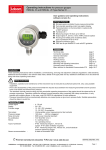
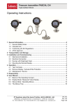
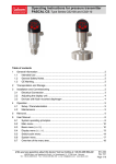
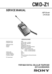
1
Resistance Thermometer Clamp-on technology for temperature measurement on pipes, Type Series GA261x Operating Instructions 1 General Information ...................................................................................................... 2 1.1 General Safety Notes .............................................................................................. 2 1.2 Intended Use ........................................................................................................... 2 1.3 Conformity with EU Regulations.............................................................................. 2 1.4 ATEX Approval........................................................................................................ 2 2 Transportation and Storage.......................................................................................... 2 3 Installation and Commissioning .................................................................................. 2 3.1 Mechanical Installation ............................................................................................ 3 3.2 Electrical Connection .............................................................................................. 5 4 Operation........................................................................................................................ 5 4.1 Calibration ............................................................................................................... 5 4.2 Maintenance / Service ............................................................................................. 6 5 Disassembly................................................................................................................... 6 Questions about this device? Hotline +49 (0) 4408 804 - 444 LABOM Mess- und Regeltechnik GmbH Im Gewerbepark 13 27798 Hude Deutschland Tel.: +49 (0) 4408 804-0 Fax: +49 (0) 4408 804-100 e-mail: [email protected] www.labom.com BA_049 Rev 1L3 Page 1/6 1 General Information This document contains necessary information for the proper installation and use of this device. In addition to this instruction, be sure to observe all statutory requirements, applicable standards, the additional technical specifications on the accompanying data sheet (see www.labom.com) as well as the specifications indicated on the type plate. 1.1 General Safety Notes The installation, set up, service or disassembly of this device must only be done by trained, qualified personnel using suitable equipment and authorized to do so. Warning Media can escape if unsuitable devices are used or if the installation is not correct. Danger of severe injury or damage Ensure that the device is suitable for the process and undamaged. 1.2 Intended Use The device is intended to measure surface temperatures as specified in the data sheet. 1.3 Conformity with EU Regulations The CE-marking on the device certifies its compliance with the applicable EU Directives for placing products on the market within the European Union. The following guidelines apply to these devices: ATEX Directive 94/9/EC (for GA26x1) EMC Directive 2004/108/EC You find the complete EC Declaration of Conformity (document no. KE_011) at www.labom.com. 1.4 ATEX Approval Devices of the type GA26x1 are certified for use in explosive environments. If you purchased a device with ATEX approval, please refer to the accompanying document XA_001 for ATEX-relevant information. 2 Transportation and Storage Store and transport the device only under clean and dry conditions preferrably in the original packaging. Avoid exposure to shocks and excessive vibrations. Permissible storage temperature: -40…100 °C When supplied with a transmitter the max. permissible storage temperature is reduced to 85 °C. 3 Installation and Commissioning The device is adapted to a certain pipe diameter as specified in the order. Before installing the device, be sure that the device is suitable for the intended process application with respect to pipe diameter, ambient and medium temperature. BA_049 Rev 1L3 Resistance Thermometer Clamp-on technology Page 2/6 3.1 Mechanical Installation Mount the device on a clean and straight pipe section free of imperfections like nicks or burrs. Mount the measuring insert at the bottom side of the pipe, if it is not completely filled with medium. First mount the clamping element, then install the measuring insert and finally make the electrical connections. 3.1.1 Mounting the clamping element There are three options how to connect the device to the process: measuring insert a) b) c) clamping element pipe Figure 1: mounting options: a) clamping block, b) clamping shoe and c) clamping bracket 3.1.1.1 Mounting the clamping block Required tools: Hexagon socket wrench 3 mm (mounting screws) Hexagon socket wrench 2 mm (vibration protection) Turn back the vibration protection, so that it does not exceed the semi-cycle groove for the pipe (see picture to the right). Mount the clamping block with the included screws at the intended position on the pipe. Do not exceed the allowed tightening torque of 2 Nm for pipe diameters up to 17,2 mm and 4 Nm for bigger pipes. Hand-tighten the vibration protection. Do not tighten the vibration protection screw too hard. You might damage the clamping block or the pipe. gap mounting screws vibration protection Figure 2: Clamping block from below BA_049 Rev 1L3 Resistance Thermometer Clamp-on technology Page 3/6 3.1.1.2 Mounting the clamping shoe Required tools: depends on the used hose clamps Mount the clamping shoe with two appropriate hose clamps or tightening straps. The maximum width for a safe fit is 5 mm. Tighten the clamps so that the clamping shoe cannot be moved by hand applying a usual hand force. 3.1.1.3 Mounting the clamping bracket In an environment with space constraints you can use the mounting bracket. Required tools: Hexagon socket wrench 3 mm Loosen the clamping bracket by unscrewing the mounting screw so that you can easily move it over the pipe. Position the clamping bracket and tighten the mounting screw. Do not exceed a tightening torque of 1 Nm. mounting screw measuring insert Figure 3: mounting bracket from above 3.1.2 Mounting the measuring insert The mounting procedure for the measuring insert is identical for all clamping elements. First apply heat conductive paste to the tip of the measuring insert. Heat conductive paste is mandatory for this type series for a good measuring accuracy. Now insert the measuring insert into the bore in the clamping element. You can position the insert in two ways. Choose the position that simplifies the later cable routing. Finally tighten the connection by turning the screw connection (see figure 4). No tools are required for this step. Never try to turn the housing, if you have a device with field housing or integrated transmitter. You might destroy the device by this. Do not turn or move the clamping element with a mounted measuring insert. You might damage or destroy the insert. Figure 4: Mounting steps for the measuring insert BA_049 Rev 1L3 Resistance Thermometer Clamp-on technology Page 4/6 3.2 Electrical Connection Complete the mechanical installation before you connect the device electrically. Set up all electrical connections while the voltage supply is switched off. M12 circular connector 3-wire circuitry cable gland transmitter 3-wire circuitry n.c. (-) (+) n.c. 2 1 6 ϑ ϑ Figure 5: Variants of electrical connection Route the cable so that it does not apply force or torque to the measuring insert. For devices with field housing, hold the housing with the other hand when you screw or unscrew the field housing cap. 4 Operation During device operation, take care that the device remains within its intended temperature range. No other monitoring is necessary. Permissible media temperature: -40…150 °C Permissible ambient temperature: -40…100 °C When supplied with a transmitter, the permissible ambient temperature is reduced to 85°C. Restricted ambient conditions may apply in explosion protected environments (see XA_001). 4.1 Calibration We recommend an annual recalibration. Uninstall only the measuring insert. This way the measuring position remains unchanged as it is defined by the clamping element. During calibration you must not exceed 100 °C at the electrical connector due to inside gaskets. If your device is equipped with an integrated temperature transmitter you must not exceed 85 °C at the housing. Apply new heat conductive paste when you reinstall the measuring insert after the calibration. This ensures a good and constant thermal coupling between insert and pipe. For further details please consult the separate calibration guideline for the Clamp-on family (TA_008). BA_049 Rev 1L3 Resistance Thermometer Clamp-on technology Page 5/6 4.2 Maintenance / Service When properly installed in accordance with applicable specifications, this device is maintenance-free. However, we recommend an annual recalibration of the device. In the event of a device malfunction, you can only replace the complete measuring insert resp. the clamping element. 5 Disassembly When measuring hot media, make sure that the device has cooled down prior to any dismounting or wear appropriate protective clothing to avoid burns. Switch off the power supply to the device before disconnecting the electrical connections. Once this is done, the device may be mechanically removed. BA_049 Rev 1L3 Resistance Thermometer Clamp-on technology Page 6/6