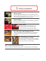
1
Operating instructions
ErgoPack 600 E
Operation of the device is only permitted if the
operating instructions have been carefully read
and understood before use!
Declaration of conformity
EU declaration of conformity
for the purposes of the EU directive 98/37/EU, Annex II A
We,
Firma ErgoPack Deutschland GmbH
Holzbrückleweg 9a
89420 Höchstädt
Germany
declare herewith, that the device "ErgoPack 600 E", to which this declaration refers
conforms to the respective safety and health requirements laid down by the EU directives,
because of its concept and type of construction and the model we have brought on to the
market.
This declaration loses its validity if a change is made to the machine without our
approval.
Respective
EU directives :
Applied standards
EU-Machine directive (98/37/EU)
EU-Low voltage directive (73/23/EEC)
EU-Guideline on electromagnetic compatibility
(89/336/EEC) in the version 93/31/EEC
EN292-1 & 2, EN294, EN349
EN60204-1, EN50081-2, EN50082-2
EN55014-2
Höchstädt, 31st. March 2005
Andreas Kimmerle
CEO
-2-
List of contents
1 Technical data
2 General
2.1 Notes on environmental protection
3 Safety regulations
3.1 Safety regulations for charger and battery
4 Description
4.1 Construction
4.2 Operating panel
4.3 Charger displays
5 Commissioning
5.1 Battery charger
5.2 Charging the battery
6 Operation
6.1 Switching on the control unit
6.2 Threading in the strap
6.3 Strapping
6.4 Strapping and sealing with the cutter
6.5.Strapping and sealing without the cutter
6.6.Strapping and sealing with the Tool-Lift
6.7 Moving the device
7 Servicing and repair
7.1 Cleaning the ChainLance
7.2 Replacing the ChainLance
7.3 Replacing individual chain links
7.4 Replacing the reversing sledge
7.5 Replacing the length stop strap
7.6 Changing the control with drive unit
8 Explosion drawings and spare parts lists
8.1 Frame, cutter, strap lifter
8.2 Storage plates
8.3 Control with drive unit / electrical parts
8.3 Reversing sledge
8.4 ChainLance
8.5 Tool-Lift
-3-
Seite
4
6
7
8
10
11
11
12
13
14
14
14
16
16
17
33
38
41
43
48
49
49
50
51
52
54
56
58
1. Technical data
Weight:
(incl. battery, without strap)
a) with cutter
b) with cutter and tool lift
75.5 kg
83.0 kg
Dimensions
length 630 mm
width 770 mm
height 1200 mm
Maximum chain speeds
Mode A, strapping
moving out, horizontally:
moving out, vertically:
moving in, vertically:
moving in, horizontally:
40 m/min
60 m/min
44 m/min
54 m/min
Mode B: setting up/inserting strap
moving out:
moving in:
20 m/min
16 m/min
Max. chain thrust:
310 N
-4-
Charger
2- stage lead charger
Prim.: 100-240 VAC 50/60Hz 1.2A
Sec.: 24V DC/2A
Total max. power 56W
Battery
Weight:
24V lead battery
12.0 kg
Charging time:
approx. 6 hours
Temperature range:
5°C - 45°C
Number of strappings:
500 to 800 per charge, depending on size of
pallet, strap tension and the extent to which
the ChainLance is dirty
Life span:
approx. 500 charges
(for discharge up to the switch-off point,
red LED lights up on the control box)
-5-
2. General
These operating instructions will help you to know the device and to use it
according to regulations. The operating instructions contain important notes
on how to use the device safely, properly and economically.
Adhering to the notes helps to avoid dangers, reduces repairs and down times
and also increases the reliability and life span of the device.
The operating instructions must be available at the place where the device
is used. They have to be read, understood and used by everybody who
works with the device. This is especially important for the operation, removal
of faults and servicing.
In addition to the operating instructions and the local rules in force for the
prevention of accidents, the recognized, specialist rules for safe working
according to proper and professional standards shall also be observed.
-6-
2.1 Notes on environmental protection
Physical or chemical materials injurious to health have not been used for
manufacturing the device.
The valid, legal regulations have to be taken into consideration during disposal.
The electrical component groups have to be dismantled, so that the mechanical,
electromechanical and electronic components can be disposed of separately.
The specialist dealer offers disposal of battery according to proper environmental
protection.
- Do not open battery
- Do not throw used battery into the domestic waste bin, into the fire or into water.
-7-
3. Safety regulations
Inform yourself!
The operating instructions have to be read carefully and
understood before using the device. The device may only be
serviced and maintained by trained personnel.
Protect yourself!
Wear eye and hand protection (cut-proof gloves) and also
safety shoes when working.
Energy source!
Before servicing and maintenance work:
Set main switch to „0“ and remove the
plug of the battery cable from the battery.
Be careful: Only strap packaging materials!
Hands or other parts of the body must not come between
the strap and the packaged materials during strapping
operations.
Be careful: Danger of crushing!
Do not reach into the chain with your fingers!
Increased danger of crushing exists especially
in the area of the reversing sledge!
Only use original ErgoPack spare parts!
The use of other than ErgoPack spare parts excludes guarantees and liability.
-8-
Make sure before each strapping operation that no other persons are in the
area of operation (especially the ChainLance) or can enter into it.
This applies especially to the area on the opposite side of the pallet on which the
operator has limited or bad view.
When the ChainLance on the opposite side of the pallet moves upwards, its own
weight causes it to fall across the pallet in the direction towards the operator.
The ChainLance can fall on top of the operator’s head if he is not careful
and can cause injuries.
You should always be careful and concentrated and should always catch the
ChainLance when it falls across the pallet.
Use in accordance with the regulations
This device is to be used for strapping pallets.
The device has been developed and constructed for safe operation
when strapping.
The device is only to be used for strapping with plastic straps
(polypropylene and polyester).
Possible misuse
Strapping with steel strap is not possible with this device.
.
-9-
3.1 Safety regulations for charger
and battery
• Check the plug and the cable before each use and have them replaced
by a specialist if damaged.
• Do not use any batteries from other manufacturers, only use original
spare parts.
• Keep the connection plug to the battery away from non-related objects
and dirt.
• Protect the charger from moisture; only operate it in dry rooms.
• Do not open the battery and protect it from shock, heat and fire.
Danger of explosion!
• Store batteries in a dry, frost proof place. The ambient temperature
must not exceed 50°C and must not fall below -10°C.
• Damaged batteries may not be reused.
- 10 -
4. Description
1
2
4.1 Construction
1
2
3
4
5
6
7
3
4
6
5
7
- 11 -
Control with drive unit
Brake block
Tool lift
Cutter
Foot lever for cutter
Sliding window with safety switch
Battery
4.2 Operating panel
8
9
10
11
8 Joystick to move ChainLance in and out,
with precision speed control.
9 LED display
Permanent light, green = battery full
Permanent light, yellow = battery will soon be empty
Permanent light, red = battery empty, control unit switches off
Flashing light all LEDs = control unit in the learning mode
Flashing light green or yellow LED = control unit in set up mode
quick flashing light, red LED = sliding window open
10 Rotary switch, strapping mode „A“/ set up mode „B“
11 Main switch “power supply 1/0“
- 12 -
4.3 Charger display
LED
LED lights up red
LED lights up orange
LED lights up green
= charger ready for use
= battery is being charged
= charging procedure finished / battery charged
- 13 -
5. Commissioning
5.1 Battery charger
The main voltage must comply with the details on the name plate.
The charger is only suitable for charging the delivered 24V
lead battery.
5.2 Charging the battery
The following points should be observed to achieve
the longest possible life span of the battery:
1.) Connect the charger to the main voltage
2.) Turn the blue ring (12) of the plug (13) on the battery (7)
to the left.
3.) Disconnect the plug (13) from the battery
4.) Insert the plug (14) of the charger in the battery (7).
7
12
13
14
- 14 -
The charging time is approximately 6 hours
The maximum charging current flows if the temperature
of the battery is between 10 - 45 °C. Avoid battery temperatures below
0 °C when loading.
The intelligent charger loads the battery with the respective, optimum
charging current. A maintenance charge flows when there is a full charge
to prevent self-draining so that the battery has a longer life span.
You achieve the longest life span, if the battery is charged daily
and is not being operated until the control unit is switched off
(red LED lights up).
- 15 -
6. Operating the device
6.1 Switching on the control unit
1. Step
- Charge the battery as described in 5.2.
- Insert the plug (13) of the power cable in the battery (7) and lock it
by turning the blue ring (12) to the right
- Turn the main switch (11) to the right to position “1“.
- Set the operating mode switch (10) to operating mode “A“.
7 12 13
2. Step
8
10
11
All 3 LEDs (green, yellow, red) are now flashing. The control unit
is in the learning mode.
Now move the joystick (8), completely in the “move out“ or the
“move in“ direction and push it until the green LED lights up. The
control unit is now ready for operational use.
- 16 -
6.2 Threading in the packaging strap
1. Step
Switch on the control unit according to 6.1.
2. Step
Set the operating mode switch (3)
to position “B“
(green LED flashes)
3
3. Step
You can use the joystick (8) to position the ChainLance so that
the red chain link is in the middle of the sliding window (6).
The sliding window must be closed during this operation!
4. Step
Open the sliding window (6) (red LED flashes quickly).
The control unit automatically switches off for safety reasons
when the sliding window is open.
6
- 17 -
5. Step
Remove the clamp
for setting the
package width
from the storage
tray.
- 18 -
6. Step
Insert the clamp into the
drilled hole at 2.0 ft (0,6m)
as shown
- 19 -
7. Step
Put the ErgoPack 600 in
front of a wall or a pallet
so that it can’t move while
you load it.
Remove the round brake
block ...
... and the red plastic disc
Adjust the three bolts
to the core diameter of
the roll of your strap.
Core diameter has been
pre-set to 406 mm.
- 20 -
8. Step
Place the roll with the
strap as shown on the
plastic disc in such a
way, that the roll
rotates clockwise
when unrolling the
strap.
9. Step
Lift the plastic wheel
together with the strap roll onto
the bearing tube by using the
hand hole (as shown).
Press with the left foot on the
wheel as shown so that the strap
roll is attached properly to the
device.
- 21 -
10. Step
Place the brake
block on the holding
device and tighten
the lever screw
clockwise until the
spring is slightly
tensioned.
Important !
To check the spring tension, turn the roll of strap
by hand. The roll must be easily turned by hand,
with a slight braking resistance.
- 22 -
11. Step
Thread the strap
through the guide
piece ...
... and over the feed
roll to the inside ...
- 23 -
12. Step
Now thread the strap as
shown from right to left
through both slots of the red
chain link.
… then over the
left slot …
… back through
the right slot.
- 24 -
Close the sliding window (6) now.
Make sure that the window is closed
up to the stop, since the safety switch for
the control unit will only unlock again
when the window is completely closed.
(red LED turns off, green LED lights up)
6
- 25 -
13. Step
Press the joystick in
the “move out“
direction until the
reversing sledge tilts
upwards.
Be careful: Danger of injury!
Never put your fingers in between
the links of the chain.
Hold the end of the
ChainLance with the
left hand while you
still continue to push
the joystick in the
“move out“ direction.
- 26 -
Move the ChainLance
out until you are able
to place it on the
device as shown ...
... and approx.
2 ft (50 cm) of
strap can be seen
- 27 -
Be careful:
Danger of injury!
14. Step
Place your left foot behind the
reversing slide in such a way, that it
cannot get pulled back into the device
when turning back the ChainLance.
15. Step
Move the ChainLance now backwards by
approx. 5 - 10 cm by quickly pushing the
joystick in the “move in“ direction until the
strap is loose.
- 28 -
16. Step
Remove the strap again
from the slots in the red
chain link and hold it
straight up, as shown.
Be careful:
Danger of injury!
17. Step
Turn the ChainLance
further back by pushing
the joystick in the “move
in” direction until only
approx. 30 cm (1 ft) stick
out from the reversing
sledge.
- 29 -
Be careful:
Danger of injury!
18. Step
Open the
eccentric latch
by pushing it
inwards with the
finger, as shown.
Push the strap from the back through
the top piece of the ChainLance, as
shown. The strap must be pushed
under the eccentric latch.
19. Step
Now hold the strap up so
that the strap and the
ChainLance are straight.
- 30 -
20. Step
Move the ChainLance
completely backwards by
pushing the joystick again in
the “move back“ direction.
Important!
Make sure that the strap
remains continuously tensioned
while the ChainLance moves
back, to avoid the strap being
pushed back into the device.
21. Step
3
Set the operating mode switch (3)
back to position “A“
22. Step
Place the overlapping strap as
shown with a loop through the
small slot underneath the left
handle.
- 31 -
23. Step
Remove the clamp
for setting of the
package width
again from the
position 2.0 ft
(0,6 m) ...
... and set the
package width as
shown. Plug the
clamp into the next
highest dimension
of your package
width.
Example 1:
Package width
0,8 m – insert
adjusting piece
at 1,0 m
Example 2:
Package width
1,2 m – insert
adjusting piece
at 1,4 m
Your ErgoPack is now ready for strapping.
- 32 -
6.3 Strapping
1. Step
Place the Ergo Pack at a
distance of ca. 1.0 ft
(30 cm) in front of the
pallet to be strapped ...
2. Step
Move the ChainLance
by pushing the joystick
in the “move out“
direction.
The reversing sledge
leads the strap through
underneath the pallet ...
- 33 -
... and up again on
the opposite side.
The device should be positioned in such a
way, that the distance between the rising
ChainLance and the pallet is approx. 0.5 ft
(15 cm).
Important!
To guarantee that the Chain
Lance remains straight it is
important, that you push the
joystick until the ChainLance
appears on the other side.
When you see the ChainLance,
keep pushing the joystick until
the ChainLance protrudes over
the package as shown.
The ChainLance falls towards
you as soon as you let go of the
joystick and you can catch the
strap.
You should always catch the
ChainLance and never let it fall
on top of the package.
- 34 -
3. Step
Hold the strap, as
shown, with the left
hand at the front,
directly at the
ChainLance ...
... and move the ChainLance
completely backwards by
pusing the joystick in the
“move in“ direction.
Important!
Proceed as follows when moving back the ChainLance:
1.) First move the ChainLance back by approx. 5 cm.
2.) Unlock the eccentric latch with a short tug on the strap,
3.) then keep the strap slightly under tension and move the
ChainLance completely backwards.
Always keep the strap slightly under tension when moving the ChainLance
backwards. The strap must not form loops or be pushed into the device
when moving the ChainLance backwards. This can lead to faults.
- 35 -
Step 4
After the reversing sledge has
moved back into the device
again, the strap lifter rises
automatically.
You now have to let the strap
slide through your left hand,
the strap lifter will not be able
to rise otherwise.
The strap lifter will give you the
strap up to working height so
that you can take it into your
hand without having to bend
over.
Keep pushing the joystick until
the strap lifter is in the
uppermost position.
The strap lifter automatically
moves down again after 2
seconds.
Important!
When the strap lifter rises, you have to hold the
strap loosely in your hand.
If you do not let go of the strap as the strap lifter
rises, the device automatically switches off to
prevent damage. The strap lifter can be raised up
again with repeated pushing of the joystick in the
“move in“ direction.
- 36 -
If you have to pull more strap out
of the device for locking, do not take
the strap directly at the strap lifter ...
... but about 10 cm below the strap
lifter. Hold the strap with the whole
hand and pull it out of the unit.
- 37 -
6.4 Strapping and sealing
with the cutter
1. Step
Measure the necessary length of
strap for locking by holding both
ends of the strap on top of each
other before you cut off the strap.
You need a strap overlap of
approx. 0.5 to 1 ft (20 - 30 cm).
If possible, hold the strap in a loop
in the right hand, as shown.
2. Step
Insert the strap loop into the
cutter, as shown ...
... and cut off the strap
by pressing the foot lever.
- 38 -
3. Step
Change the position
of the two ends of the strap
(upside down and
downside up)
as shown on the picture.
The end which was cut just
before must be placed at
the bottom.
4. Step
Hold the two ends of the
strap with your left hand
at the end
of the upper strap.
Place the front left hand
corner of the locking
tool at an angle on the
strap as shown ...
- 39 -
... and thread the strap
into the locking tool.
The locking tool
cuts off the protruding ends
of the strap after strapping and
sealing.
Important!
The length of the waste piece depends on the accuracy
of your measuring before cutting off with the cutter.
- 40 -
6.5 Strapping and sealing
without the cutter
Turn the locking
tool by 180° and hold
it with the left hand.
Important!
If you turn the locking tool, you must hold it, as shown, with your
left hand and thread the strap into the locking tool with your right
hand accordingly.
- 41 -
Push the
overlapping strap as
shown into the small
slot underneath the
left handle.
Then put the locking
tool into the storage
tray.
- 42 -
6.6 Strapping and sealing with the
ErgoPack Tool-Lift
1.Step
Fasten the adapter,
as shown, into the
threaded holes of
the locking tool.
2.Step
Push the locking tool
with the adapter into
the holder on the tool
lift.
To do so, unlock the
plunger by pulling
the black knob.
Important!
Make sure that the plunger snaps back into position and that the locking
tool is fastened.
- 43 -
Important!
The ErgoPack Tool-Lift has been specially designed to strap high pallets.
It requires a minimum pallet height of at least 3.0 ft (1 m) or more.
If you work with the ErgoPack Tool-Lift you should keep a larger distance
between the ErgoPack and the pallet than when using the ErgoPack 600
without the Tool-Lift.
The distance to the pallet should be approx. 1 to 1.5 ft (30 to 45 cm).
This may require setting a wider pallet width at the ErgoPack than
when working without the Tool-Lift.
- 44 -
3. Step
Hold the strap with the
right hand. The end of
the strap must be at the
bottom.
4. Step
Push the locking tool
towards the pallet with the
left hand and press the
handle to open the strap
clamp of the locking tool.
With your right hand you
can now feed the strap into
the locking tool.
Please watch the „Tool-Lift
Video-CD“ where we show
exactly the best way of
doing this.
- 45 -
5. Step
If you work with corner protectors, let the locking tool move back before
tightening the strap. The Tool-Lift will hold the locking tool and keep
the strap tensioned. You can now fit the corner protectors underneath the
strap.
- 46 -
6. Step
Tighten and seal the
strap.
The locking tool is
automatically pulled
towards the package
when the strap is
tightened.
7. Step
Pull the lever for opening the
strap clamp to remove the
locking tool.
Then pull the locking tool
upwards and to the left.
- 47 -
6.7 Moving the device
You can either move
your ErgoPack in a
vertical standing
position ...
... or push it in the
tilted position.
Obstacles such as
stairs, for example, can
be overcome in the
tilted position.
- 48 -
7. Servicing and repair
Your ErgoPack is made out of galvanized steel and ultra wear-resistant
plastic materials and is basically maintenance-free.
Clean the outside of the ErgoPack with a damp cloth if it is extremely
dirty.
Be careful: Danger of injury!
The main power cable must be disconnected
from the battery and the main switch must be
set to the “0“ position for all servicing and
repair work.
7.1 Cleaning the ChainLance
Clean the ChainLance with acetone or petroleum if it has become dirty
with oil.
Be careful: Do not place the ChainLance in the cleaner.
Then spray the ChainLance with commercially obtainable silicone spray.
Be careful: Never use other lubricants such as grease or oil, etc. under
any circumstances.
- 49 -
7.1 Replacing the ChainLance
1. Step
Disconnect the main power
cable from the battery.
2. Step
Pull out the reversing slegde
by about 3 ft (1 m), pull the
ChainLance out of the
device as shown and roll it
up.
3. Step
Push the new ChainLance
in again in the reverse
sequence.
- 50 -
7.2 Replacing individual chain links
The ChainLance can be opened as described in point 7.3 to replace individual
broken chain links.
A defective chain link can also be removed without having to fit a new
chain link. The control unit adjusts automatically to the current length of the
ChainLance after each strapping operation.
Important!
You have to make sure that no chain links are fitted the wrong way
if individual chain links have to be exchanged.
Each chain link has the lettering „ErgoPack“ on one side.
Make sure that this lettering appears on the same side of the chain links
to be installed as the others.
The device can no longer be used if only one individual chain link
has been fitted the wrong way.
- 51 -
7.3 Replacing the reversing sledge
1. Step
Disconnect the main
power supply cable from
the battery.
2. Step
Pull the reversing sledge
out of the device by about
3 ft (1 m), fold up the
hinge at the reversing
sledge and pull about
2.5 ft (80 cm) of the chain
upwards, as illustrated.
3. Step
Use a screwdriver to push
between the sides of two
chain links and carefully
turn the screwdriver to
twist the sides apart until
both chain links can be
completely separated
from each other.
- 52 -
4. Step
Push the ChainLance back
into the device until it has
completely moved out
of the reversing sledge.
5. Step
Place the reversing sledge
on its top, as illustrated
and use a screwdriver to
unscrew both screws
of the length stop strap.
6. Step
Fitting is done in the reverse sequence for dismantling.
Important!
Both screws of the length stop strap must be protected with
screw retaining varnish.
- 53 -
7.4 Replacing the length stop strap
1. Step (dismantling)
Perform all 5 steps listed in point 7.3 and then proceed to step 2.
2. Step (dismantling)
Remove the screw at position 2.4 m.
3. Step (dismantling)
Pull out the length stop strap.
- 54 -
4. Step (installation)
Push the ChainLance all the way
back into the device so that you
can see the guide slot of the length
stop strap.
5. Step (installation)
Push the length stop strap into the
small slot below the slot for the
ChainLance.
Important!
Make sure that you do not push the length stop strap into the slotted
track of the ChainLance!
The further installation is done in the reverse sequence for
dismantling.
The screw at 2.4 m may only be tightened until the stop nut
engages. The screw must still be loosely positioned in the hole.
If the screw has been tightened up too much, the storage plates
will be pressed together, the ChainLance and the length stop strap
could become jammed.
- 55 -
7.5 Changing the control with drive unit
1. Step
Disconnect the power cable
plug and the plug of the
safety switch for
the sliding window.
2. Step
Remove the 5 covering caps
in the storage plate.
- 56 -
3. Step
Use a 4 mm allen key to
first remove the four screws
of the drive shaft.
You have to turn the gearwheel
by pushing the ChainLance
until you can see and remove
the individual screws.
4. Step
Remove the fifth screw now.
Hold the control box firmly
when you do this.
5. Step
Pull off the control box.
Make sure that you do not
loose the small adjustment
spring on the drive shaft.
6. Step
The control box is mounted
in the reverse sequence for
dismantling.
- 57 -