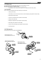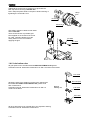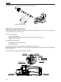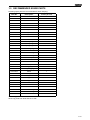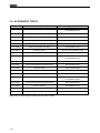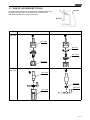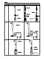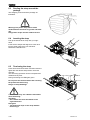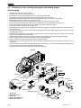
1
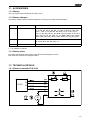
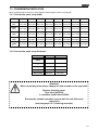
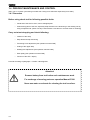
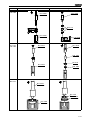
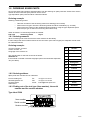
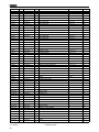
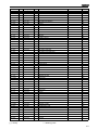
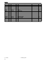
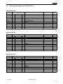
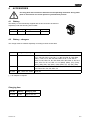
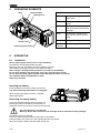
1.
SERVICE MANUAL P326.0001.01
2.
DRAWINGS P326.0001.01
3.
SPARE PARTS LISTS P326.0001.01
Type independent spare parts
Type dependent spare parts
4.
MANUAL P326.0001.01
Technical Data
Chart of Types
Exchange of wearing parts
5.
SERVICE MANUAL P327.0001.01
6.
DRAWINGS P327.0001.01
7.
SPARE PARTS LISTS P327.0001.01
Type independent spare parts
Type dependent spare parts
8.
MANUAL P327.0001.01
Technical Data
Chart of Types
Exchange of wearing parts
9.
10.
11.
NEWS
12.
NOTES
SERVICE MANUAL
BATTERY - POWERED
PLASTIC STRAPPING TOOL
MODEL P326.0001.01
P326.0001.01.sen.fm/MAS./©02.10
P326.0001.01.sen.fm/MAS/©
11.05
Manual for authorized dealers and service points
1-1
INDEX
PAGE
1.1
1.1.1
1.1.2
1.1.3
ACCESSORIES
Battery . . . . . . . . . . . . . . . . . . . . . . . . . . . . . . . . . . . . . . . . . . . . . . . . . . . . . . .
Battery chargers . . . . . . . . . . . . . . . . . . . . . . . . . . . . . . . . . . . . . . . . . . . . . . .
Battery tester . . . . . . . . . . . . . . . . . . . . . . . . . . . . . . . . . . . . . . . . . . . . . . . . . .
1-3
1-3
1-3
1-3
1.2
1.2.1
1.2.2
1.2.3
TECHNICAL DETAILS
Electric schematic ELS.1044 . . . . . . . . . . . . . . . . . . . . . . . . . . . . . . . . . . . . .
Connecting plan. . . . . . . . . . . . . . . . . . . . . . . . . . . . . . . . . . . . . . . . . . . . . . . .
Strap tension . . . . . . . . . . . . . . . . . . . . . . . . . . . . . . . . . . . . . . . . . . . . . . . . . .
1-3
1-3
1-4
1-4
1.3
1.3.1
1.3.2
CONVERSION PARTS P326
1-5
Conversion parts: strap width . . . . . . . . . . . . . . . . . . . . . . . . . . . . . . . . . . . . . 1-5
Conversion parts: strap thickness . . . . . . . . . . . . . . . . . . . . . . . . . . . . . . . . . 1-5
1.4
1.4.1
1.4.2
1.4.3
1.4.4
1.4.5
1.4.6
1.4.7
PERIODIC MAINTENANCE AND CONTROL
1-6
Procedure . . . . . . . . . . . . . . . . . . . . . . . . . . . . . . . . . . . . . . . . . . . . . . . . . . . . 1-6
Troubleshooting. . . . . . . . . . . . . . . . . . . . . . . . . . . . . . . . . . . . . . . . . . . . . . . . 1-7
Battery test . . . . . . . . . . . . . . . . . . . . . . . . . . . . . . . . . . . . . . . . . . . . . . . . . . . 1-9
Checklist . . . . . . . . . . . . . . . . . . . . . . . . . . . . . . . . . . . . . . . . . . . . . . . . . . . . . 1-9
Glueing rules . . . . . . . . . . . . . . . . . . . . . . . . . . . . . . . . . . . . . . . . . . . . . . . . . . 1-9
Lubrication rules . . . . . . . . . . . . . . . . . . . . . . . . . . . . . . . . . . . . . . . . . . . . . . 1-10
Assembly information . . . . . . . . . . . . . . . . . . . . . . . . . . . . . . . . . . . . . . . . . . 1-11
1.5
RECOMMENDED SPARE PARTS
1-15
1.6
ACCESSORY TOOLS
1-16
1.7
USE OF ACCESSORY TOOLS
1-17
1.8
1.8.1
1.8.2
1.8.3
ORDERING SPARE PARTS
Ordering manuals . . . . . . . . . . . . . . . . . . . . . . . . . . . . . . . . . . . . . . . . . . . . .
Ordering address. . . . . . . . . . . . . . . . . . . . . . . . . . . . . . . . . . . . . . . . . . . . . .
Finding out of the tool type (item number),
the serial number and the version number: . . . . . . . . . . . . . . . . . . . . . . . . . .
1-21
1-21
1-21
1.9
SERVICE ADDRESS
1-22
1.10
CHART OF TYPES
1-22
1-2
1-21
1.1 ACCESSORIES
1.1.1 Battery
Use only original Fromm batteries N5.4330 (Li-Ion).
1.1.2 Battery chargers
The battery charger must be ordered separately according to the table mentioned below.
Item-No.
Voltage / frequency
Admitted for country
N5.4443
220 - 240V / 50 - 60Hz
A, B, BG, BIH, BOL, BR, BY, CH, CL, CZ, D, DK, DZ, E, EAS, EST,
ET, F, FIN, GE, GR, H, HK, HR, I, IL, IND, IR, IRQ, IS, JOR, KSA,
KWT, L, LAR, LT, LV, MA, MC, MK, MOC, N, NL, P, PK, PE, PL,
PRC, PY, RA, RCH, RI, RL, RO, ROK, ROU, RP, RUS, S, SK, SLO,
SYR, THA, TN, TR, UA, UAE, YU, YV, (BRN), (BRU), (CY), (EAK),
(EAT), (GB), (IRL), (M), (MAL), (OM), (SGP), (Y), (Z), (ZA), (ZW)
N5.4447
120V / 50 - 60Hz
BR, C, CDN, CO, CR, DOM, EC, GCA, J, JA, KSA, LB, MEX, NIC,
PA, Puerto Rico, RC, RP, USA, YV
N5.4445
220 - 240V / 50 - 60Hz
AUS, NZ
(..) = an adaptor is required
1.1.3 Battery tester
For testing the batteries order battery tester N7.5146 and adapter N7.5145.
Both parts are required for testing the battery.
1.2 TECHNICAL DETAILS
1.2.1 Electric schematic ELS.1044
18VDC
-
black
DC
black
DP
red
+
red
red
+
black
M
-
1-3
1.2.2 Connecting plan
N5.2368
red (+)
red
black (-)
black
red (+)
N5.2367
black (-)
To connect the electronic to the motor see also 1.4.7 Assembly information.
1.2.3 Strap tension
The tension force values mentioned in the operation manual (400-2400N) are not achievable with each strap.
They depend on following factors:
• Hardness of the package,
the maximum tension force values are achievable with hard packages.
• Elongation and creep properties of the plastic strap,
the maximum tension force values are achievable by using plastic straps with a low elongation.
• Surface quality of the plastic strap,
the maximum tension force values are achievable with waxed and embossed straps.
• Strap width, strap thickness,
the maximum tension force values are achievable with thick and wide straps.
1-4
1.3 CONVERSION PARTS P326
When changing strap thickness or strap width the following parts must be exchanged:
1.3.1 Conversion parts: strap width
10mm
11.1mm
12mm
12.7mm
13mm
15mm
15.5mm
16mm
Guide
pin
P30.1156
P30.1158
P30.1156
P30.1157
P30.1158
P30.1159
P30.1160
P30.1161
Guide
pin
P30.1162
P30.1164
P30.1162
P30.1163
P30.1164
P30.1165
P30.1166
P30.1167
Guide
case
P32.1205
P32.1205
P32.1206
P32.1206
P32.1206
P32.1206
P32.1206
P32.1206
Strap
stop
P32.2082
P32.2083
P32.2084
P32.2085
P32.2085
P32.2086
P32.2087
P32.2087
Strap
guide
P32.2089
P32.2090
P32.2091
P32.2095
P32.2095
P32.2092
P32.2096
P32.2096
1.3.2 Conversion parts: strap thickness
0.4-0.64mm 0.65-1.05mm
Tensioning
wheel
P32.1219
P32.1220
Gripper
P32.1222
P32.1225
Gripper
P32.1223
P32.1226
Gripper
P32.1224
P32.1227
Steel insert
P32.1201
P32.1202
Attention!
When converting tools always change the item number on the type label
Replace following parts:
Type label N43.9190
2 x hammer head bolts N2.4902
Enclose the suitable operation manual with the tool after each
conversion
(see paragraph 1.8.1 Ordering manuals).
1-5
1.4 PERIODIC MAINTENANCE AND CONTROL
(Carry out 12- months cycles doing one shift work. Doing more shift work respectively more often.)
1.4.1 Procedure
Before using check tool for following possible faults:
•
Visual test of the tool for loose, lost or damaged parts
•
Clean all dirty parts of the tool, especially strap abrasion in the tensioning or the welding unit by
using compressed air. (Never use any hard tools like a wire brush or a screw driver for cleaning)
Carry out a test strapping and check following:
•
Insertion of the strap
•
Strap feed and strap tensioning
•
Tensioning force adjustment (see operation manual P326)
•
Cutting of the upper strap
•
Welding time adjustment (see operation manual P326)
•
Seal quality (see operation manual P326)
•
Function of the LED - display
Proceed according to paragraph 1.4.2 after a fault appears.
Attention!
Remove battery from tool before each maintenance work.
For exchange of wearing parts see operation Manual P326.
Never use water or solvents for cleaning the tool’s surface.
1-6
1.4.2 Troubleshooting
Ensure before each tool repair that the battery is charged and
the tool’s specific strap is used
SYMPTOM
CAUSE
REMEDY
Tool doesn’t work at all
Battery is empty or defective
Charge or replace battery
Contact problems caused by a broken
battery housing
Replace battery
Contact problems caused by a
damaged insertation part N51.2194 or
damaged motor housings P32.2079
and P32.2080
Replace cover insertation part or
motor housing
Contact problem of the internal wires
Check contacts and fix them if
required or change defective parts
Defective circuit board
Replace circuit board
Defective motor P32.2078
Replace motor
Tensioning wheel is dirty or worn
Clean tensioning wheel or replace it,
don’t use any hard objects for this
(see operation manual P326)
P32.1051 is not meshing with
P32.1048, because spring N2.5822 is
defective or parts are dirty
Replace spring N2.5822,
clean dirty parts
Faulty tensioning wheel or tensioning
wheel is assembled reversed
Correct assembling
(see operation manual P326)
Grippers are dirty, worn or wrongly
assembled
Replace grippers, clean them or
assemble correct,
don’t use any hard objects for this
(see operation manual P326)
Gearing parts from the tensioning gear
are defective
Check tensioning gear and replace
defective parts
Defective circuit board
Replace circuit board
Micro switch N5.2368 for tensioning
is defective
Replace micro switch
Defective gear bearings
Replace bearings
Defective tensioning body
Replace tensioning body
Needle free wheeling in gear wheel
P32.0156 or in conical gear wheel
P32.0151 assembled reversed
or defective
Assemble the needle free wheeling
correct or replace it
Defective needle free wheeling
N3.4509 in P32.0156
Check parts and replace if necessary
Tool doesn’t tension
Tensioning wheel turns
back immediately after the
tensioning cycle
1-7
SYMPTOM
CAUSE
REMEDY
Tool doesn’t weld
Welding gripper P32.1053 is dirty or
worn
Replace or clean welding gripper,
don’t use any hard objects for this
(see operation manual P326)
Welding stop gripper P32.1203 is dirty Replace or clean welding stop gripper,
or worn
don’t use any hard objects for this
(see operation manual P326)
Damaged housing parts
Replace housing parts
Defective circuit board
Replace circuit board
Pressure spring N2.5294 defective
Replace pressure spring
Needle free wheeling N3.4509 in
P32.0150 defective or assembled
reversed
Assemble the needle free wheeling
correct or replace it
Gearing parts of the welding gear are
defective
Check welding gear and replace
defective parts
Micro switch N5.2367 for welding is
defective
Replace micro switch
Defective gear bearing
Replace bearing
Cutter is worn or damaged
Replace cutter
(see operation manual P326)
Wrong adjustment of the coupler
P32.1250
Check adjustment and readjust if
necessary
(see operation manual P326)
Welding gripper is worn
Replace welding gripper
(see operation manual P326)
Welding time too short
Change adjustment
(see operation manual P326)
Defective pressure spring N2.5237
Replace pressure spring
Tool switches off after a few
strappings
(Displaying empty battery)
Battery defective or empty
Check the battery and change
defective batteries
Gear noise
Tensioning or welding gear is worn
Check component parts and replace
defective ones
Tool badly cuts the strap or
doesn’t cut at all
1-8
1.4.3 Battery test
For testing the batteries order battery tester N7.5146 and adapter N7.5145.
Both parts are required for testing the battery.
The use is described in the instruction manual of the battery tester.
• Li-Ion-Batteries 18V / (3Ah) must be replaced at a capacity less than 60% (1,8Ah).
1.4.4 Checklist
Carry out some test strappings and check following tool components.
•
Inserting of the strap
•
Insert battery in the tool and check function of the LED-display (see operation manual P326)
•
Strap feed and strap tension
•
Tension force adjustment (see operation manual P326)
•
Cutting of the upper strap
•
Welding time adjustment (see operation manual P326)
•
Seal quality (see operation manual P326)
•
Function of the LED-display (see operation manual P326)
•
Correct type label
1.4.5 Glueing rules
Following parts have to be glued with LOCTITE 603:
N2.2145
Planet shaft P32.1044
with the parallel pins N2.2145.
Tensioning body P32.2088
with the parallel pins N2.2189
P32.2088
P32.1044
P32.2001
Body P32.2001 with
swivel shaft P32.2017
and parallel pins N2.2188
N2.2188
N2.2189
P32.2017
1-9
Additional the screws N1.2112 have to be glued with the
idler step P32.0118 using LOCTITE 222.
Don’t clamp the planet shaft on the pinion while loosening or
tightening the screws N1.2112.
clamp
here
N1.2112
P32.0118
Glue safety washer N1.6505 on both sides
with Loctite 243.
There should as less as possible glue
been applied on the thread of the screw
N1.1922. Therefore please move the
safety washer on the screw before
applying the glue.
N1.6505
N1.1922
1.4.6 Lubrication rules
All gear parts have to be lubricated with MOLYKOTE BR2 PLUS grease.
Lubrication interval: While each maintenance or after 12 months at the latest.
P32.1029
All bearing parts of the welding unit have to be cleaned and
lubricated with Klüber Isoflex Alltime SL2 grease while
each maintenance.
Lubrication interval: While each maintenance or after 12
months at the latest.
N3.1702 (6X)
Bearing
welding unit
P32.1027
P32.1053
All other parts have to be greased due to the explosion drawing.
Lubrication interval: While each maintenance
1-10
1.4.7 Assembly information
By installing the grippers into the tensioning
body P32.2088 it must be observed the
direction of the teeths.(look at the picture)
P32.2088
Grippers
Like imaged the connections of the motor P32.2078 must be adjusted 90° to the sheet P32.2064.
The mounting of the sheet happens by fixation of the disk P32.2121 with the screws N1.2216.
To adjust the sheet the motor could be placed into the housing.
X
P32.2078
View X
P32.2064
(+)
P32.2121
P32.2064
90°
N1.2216
(-)
Pay attention to the mounting position of the needle free wheelings N3.4509 and N3.4520.
The rolling direction is stamped in at the front side of the free wheelings.
N3.4509
P32.2015
N3.4520
P32.2036
P32.2018
N3.4509
1-11
Pay attention to the mounting position of the eccentric (P32.2034).
(P326) Eccentric behind
Adjustment of the lever P32.1414
If the handle lever after welding and cooling of the strap can be pulled up difficult or not at all, the adjustment
of the lever P32.1414 must be checked.
It can be done as follows:
-
Loose lock nut N1.5120
Screw in the socket set screw N1.3150, until it touches the coupler P32.1410
Tighten lock nut N1.5120
Test without battery and strap:
-
Press welding lever down until it locks
Pull handle lever up
The welding lever must move up before the tension body swings forward.
Swings the tension body forward first, the strap blocks the welding jaw and the handle lever can be pulled up
difficult or not at all.
Afterwards do a test strapping and readjust if necessary.
P32.1410
N1.5120
N1.3150
P32.1414
Welding lever
Tension body
1-12
P32.1422
Handle lever
Connection of the circuit board to the motor
In order to prevent a cracking of the terminals on the motor, the connection cables of the circuit board have to
be laid as shown on the pictures before they are soldered to the motor.
1-13
Mounting of the dowel P32.2123
The dowel P32.2123 has to be mounted between motor and circuit board like shown.
1-14
1.5 RECOMMENDED SPARE PARTS
Following spare parts are recommended for stock keeping:
Item-No.
Description
Pieces per tool
N1.1305
Screw
2
N1.1904
Screw
5
N1.1909
Flat head screw
2
N1.1927
Flat head screw
2
N1.1929
Screw
1
N1.1934
Flat head screw
3
N1.6503
Safety washer
6
N1.6504
Safety washer
12
N1.6505
Safety washer
3
N1.7206
PT-screw
1
N1.7211
PT-screw
6
N2.1118
Security ring
1
N2.1121
Security ring
5
N2.1606
Spring ring
1
N2.1805
Tensioning ring
1
N3.1702
Ball
6
N3.4509
Free wheeling
2
N3.4520
Free wheeling
1
N51.2194
Insertation part
1
N5.2367
Micro switch
1
N5.2368
Micro switch
1
P32.0153
Body
1
P32.1053*
Welding gripper
1
P32.1203*
Welding stop gripper
1
P32.1204*
Cutter
1
P32.1219/20*
Tensioning wheel
1
P32.1222/25*
Gripper
1
P32.1223/26*
Gripper
1
P32.1224/27*
Gripper
1
P32.1238
End cover
1
P32.2026
Lever
1
P32.2078*
Electric motor
1
P32.2079
Motor housing
1
P32.2080
Motor housing
1
P32.2081
Circuit board
1
* = wearing parts
Stock only parts from tools that are in sale.
1-15
1.6 ACCESSORY TOOLS
Item number
Description
Application
N71.3235
Press in and press out arbor
N3.4509/P32.2036;
N3.4509/P32.2015
N71.3237
Press in and press out arbor
N3.1159/P32.2016
N71.3239
Press in arbor
N3.2347/P32.1024
N71.3240
Press out arbor
N3.2347/P32.1024
N71.3241
Press in and press out pressure pad
N3.2347/P32.1024
N71.3242
Press in and press out arbor
N3.2346/P32.1238
N71.3243
Press in arbor
N3.1134, P32.1023/P32.1022
N71.3244
Press out arbor
N3.1134, P32.1023/P32.1022
N71.3245
Pressure pad
N3.1134, P32.1023/P32.1022;
N3.2346/P32.1238
N71.3246
Press in and press out arbor
N3.1157/P32.1044
N71.3247
Press in and press out pressure pad
N3.1157/P32.1044
N71.3248
Press in arbor
N3.3172/P32.2088
N71.3249
Press out pressure pad
N3.3172/P32.2088
N71.3250
Press in and press out arbor
N3.3172/P32.2001; N3.3172/P32.2088
N71.3282
Press in and press out pressure pad
N3.4509/P32.2015; N3.4520/P32.2018;
N3.4509/P32.2036
N71.3283
Press in and press out pressure pad
N3.1159/P32.2016
N71.3284
Press out arbor
N3.4520/P32.2018
N71.3285
Press out pressure pad
N3.1137/P32.2015
N71.3286
Press out arbor
N3.1137/P32.2015
Partly some of these tools are already used for other models.
1-16
1.7 USE OF ACCESSORY TOOLS
N7.5108
Accessory tools should only be used with the suitable arbor press
N7.5108 to prevent a jam of the parts have to be pressed in.
Additional a retainer (N7.3215) is necessary.
N7.3215
Part
Disassembly
Assembly
N3.1157/
P32.1044
N71.3246
N3.1157
P32.1044
N71.3247
N3.2346/
P32.1238
N71.3242
N3.2346
P32.1238
N71.3245
1-17
Part
Disassembly
Assembly
N3.2347/
P32.1024
N71.3239
N71.3240
N3.2347
P32.1024
N71.3241
The seal of the
needle bushing
(N3.2347) has
to face to the
outside.
N3.3172/
P32.2001
N71.3250
N3.3172
N3.4509/
P32.2036
P32.2001
N71.3235
N3.4509*
P32.2036
N71.3282
*Pay attention to the
assembling direction
see assembly information
1-18
Part
N3.3172/
P32.2088
Disassembly
Assembly
N71.3250
N71.3248
N3.3172
N71.3249
P32.2088
P32.1023/
N3.1134/
P32.1022
N71.3244
N71.3243
P32.1022
N3.1134
N71.3245
P32.1023
P32.2016/
N3.1159
N71.3237
N3.1159
P32.2016
N71.3283
1-19
Part
Disassembly
Assembly
P32.2015/
N3.1137
N71.3286
N3.1137
N71.3285
P32.2015
P32.2018/
N3.4520
N71.3284
N3.4520
N71.3282
P32.2018
P32.2015/
N3.4509
N71.3235
N3.4509
P32.2015
N71.3282
1-20
1.8 ORDERING SPARE PARTS
On principle spare part numbers should be taken from the drawings or spare parts lists. Check if the version
number of the tool and the spare parts list are the same.
Type dependent spare parts should be ordered as follows:
Ordering example
Ordering a tensioning wheel:
•
•
•
Take item numbers of the tensioning wheel from drawing (P32.1219/20)
Find out the tool type in which the tensioning wheel should be assembled (e.g. 43.2223)
Find out the item number of the needed tensioning wheel by using the type dependent spare
parts lists (for type 43.2223 it is tensioning wheel P32.1219).
Order as follows if 10 tensioning wheels are needed:
P32.1219
Tensioning wheel
10 pcs.
1.8.1 Ordering manuals
When converting tools make sure that the used manual has still validity.
If tools change their item number because of the conversion (see chart of types) the adequate manual must
be ordered as follows.
Ordering example:
Tool item number: 43.2223
Version number: 01
Language of the manual: de
The manual order for this tool must look as follows:
43222301.de
If the manual is needed in another language replace the shorthand expression
"de" (see table).
1.8.2 Ordering address
Spare parts and manuals can be ordered at:
Fromm Holding AG
Hinterbergstrasse 26
CH-6330 Cham
Switzerland
Tel.:
Fax:
e-mail:
+41(0) 41 741 57 41
+41(0) 41 741 57 60
[email protected]
1.8.3 Finding out of the tool type (item number), the serial
number and the version number:
de
German
en
English
fr
French
it
Italian
nl
Dutch
po
Portuguese
se
Swedish
fin
Finnish
sp
Spanish
ru
Russian
cz
Czech
hu
Hungarian
pl
Polish
sk
Slovakian
tr
Turkish
Type label P326
Item number
Version number
{
Serial number
1-21
1.9 SERVICE ADDRESS
You will get further assistance and information at:
Fromm System GmbH
Technical customer support
Neulandstr. 10
D-77855 Achern
Germany
Phone:
Fax:
+49(0)7841 / 62 94-22
+49(0)7841 / 62 94-11
e-mail:
[email protected]
1.10CHART OF TYPES
Item no.
1-22
Model
Strap width
Strap thickness
43.2201
P326/10/0.40-0.64
10 mm / 3/8"
0.40-0.64 mm / .016 - .025"
43.2202
P326/10/0.65-1.05
10 mm / 3/8"
0.65-1.05 mm / .026 - .041"
43.2211
P326/11.1/0.40-0.64
11.1 mm / 7/16" 0.40-0.64 mm / .016 - .025"
43.2212
P326/11.1/0.65-1.05
11.1 mm / 7/16" 0.65-1.05 mm / .026 - .041"
43.2221
P326/12/0.40-0.64
12 mm
0.40-0.64 mm / .016 - .025"
43.2222
P326/12/0.65-1.05
12 mm
0.65-1.05 mm / .026 - .041"
43.2223
P326/12.7/0.40-0.64
12.7 mm / 1/2"
0.40-0.64 mm / .016 - .025"
43.2224
P326/12.7/0.65-1.05
12.7 mm / 1/2"
0.65-1.05 mm / .026 - .041"
43.2231
P326/13/0.40-0.64
13 mm
0.40-0.64 mm / .016 - .025"
43.2232
P326/13/0.65-1.05
13 mm
0.65-1.05 mm / .026 - .041"
43.2251
P326/15/0.40-0.64
15 mm
0.40-0.64 mm / .016 - .025"
43.2252
P326/15/0.65-1.05
15 mm
0.65-1.05 mm / .026 - .041"
43.2253
P326/15.5/0.40-0.64
15.5 mm
0.40-0.64 mm / .016 - .025"
43.2254
P326/15.5/0.65-1.05
15.5 mm
0.65-1.05 mm / .026 - .041"
43.2261
P326/16/0.40-0.64
16 mm / 5/8"
0.40-0.64 mm / .016 - .025"
43.2262
P326/16/0.65-1.05
16 mm / 5/8"
0.65-1.05 mm / .026 - .041"
P326.0001.01.en.z
7
1 Nm
6 Klüber Isoflex NBU 15
5 Klüber Isoflex Alltime SL2
4 Loctite 222
3 Loctite 603
2 Molykote BR 2 plus
1
N2.3342
P32.2001
N3.3172
1 Mobilux EP2
D
C
B
A
P32.0176
P32.1216 1
P32.1050 1
P32.2017 3
3 N2.2188
P32.0153
2
N1.1909
N1.6505
3 N2.2189
N3.3172
P32.1228
P32.1229
N3.1172
N2.2187
3
N2.5823
P32.2082/83/84/85/86/87*
N1.2230
P32.2088
N1.2230
N3.2346
N3.1172
P32.1219/20 2
N2.2187
P32.1218 2
P32.2089/90/91/92/95/96*
P32.1222/25*
P32.1223/26*
P32.1224/27*
P32.1217 2
N3.2106 2
4
5
N1.1904
N1.6503
N2.4902
N4.9159
P32.1238
P32.0110
6
2
DRAWING P326.0001.01
*See 1.8 Ordering spare parts
2-1
*See 1.8 Ordering spare parts
2-2
P326.0001.01.en.z
N1.1952
N43.9190
N2.4902
P32.2067
7
P32.1201/02*
P32.1011
1 P32.2026
P32.2020
P32.1203
D
C
B
N1.6504
A
4 N1.1305
N2.2110
N1.6504
P32.2001
1 N2.5157
1 N2.5295
1 P32.1403
1 N2.5294
N2.2443
N3.3174
8
1 P32.1410
10
N2.2193
P32.1249
P32.0173
N2.1121
P32.1053 5
P32.1028 6
1 P32.1204
P32.1029 5
N2.5237
N2.1121
1 P32.1035
P32.1032
N2.5178
P32.1035 1
5 N3.1702 (6x)
5 P32.1027
1 N2.5296
P31.1124
P32.0139
9
1 P32.1012
N3.3174
P32.1405 1
P32.1404 1
P32.2023
N1.1553
P30.1156/57/58/59/60/61*
P30.1162/63/64/65/66/67*
12
7
P32.1250
1 Nm
6 Klüber Isoflex NBU 15
5 Klüber Isoflex Alltime SL2
4 Loctite 222
3 Loctite 603
2 Molykote BR 2 plus
1 Mobilux EP2
N1.1904
N1.1929
P32.1211
N41.9127
N1.6503
P32.1208
P32.1252
P32.1251
P32.1248
P32.1210
P32.1210
N2.1121
N1.6504
P32.1205/06*
11
P326.0001.01.en.z
2-3
P32.0173
P32.0154
1 Nm
8 Loctite 243
7
6 Klüber Isoflex NBU 15
5 Klüber Isoflex Alltime SL2
4 Loctite 222
3 Loctite 603
13
P32.2035 2
2 Molykote BR 2 plus
1 Mobilux EP2
D
C
B
A
P32.0120
N3.4509
1 P32.1051
N2.5822
N1.6344
N2.1805
P32.0156
2 P32.2036
N3.1178
P32.1048 2
N1.6331
N3.1160
14
3 N2.2145
P32.0118
N3.2347
6 P32.1024
N2.2119
P32.2012
N1.1922
8 N1.6505
P32.1411 1
1 P32.2032
3 N3.1159
N1.6331
18
P32.1021
P32.2001
N1.6331
2 P32.1023
N3.1134
2 P32.2016
P32.1022
17
N2.2190
N3.2347
P32.0144
P32.0140
N3.1134
16
N2.2122
N3.1157
2 P32.1044
P32.1412
N3.2105 2
P32.1046 2
P32.1047
P32.2034
N1.6331
N1.2112 4
N2.1610
15
2-4
P326.0001.01.en.z
P32.0173
P32.0175
N1.6504
7
1 Nm
6 Klüber Isoflex NBU 15
5 Klüber Isoflex Alltime SL2
4 Loctite 222
3 Loctite 603
2 Molykote BR 2 plus
1 Mobilux EP2
D
C
B
19
N1.1927 7
7 N1.1934
7 N1.1934
A
P32.2123
(P32.2009)
N2.1606
(N5.2368)
(N3.3174)
(N1.7206)
N43.9164
N5.2702
N1.7211
20
(N5.2367)
P32.2081
P32.0151
N61.6216
N43.9192
21
N21.5124
N51.2194
N3.1137
N31.1118
P32.0149 2
N31.1120
P32.2018 2
N3.4520
P32.2030
P32.2080
22
N2.5153
P32.2006
P32.2078
P32.2121
P32.0172
N1.2216
P32.2001
(N3.3174)
P32.1011
24
P32.2015 2
N2.1118
N1.3150
N1.5120
P32.1414
N43.9192
P32.2079
P32.0150
N3.4509
N3.1137
1 P32.1422
P32.1415
P32.2024
P32.2064
N61.6216
23
3
SPARE PARTS LIST P326
3.1 Type independent spare parts P326.0001.01
Item-No.
in group
N1.1305
Pcs.
Description
Dimension
Field
2 SCREW
M4 X 7.8
D8
1 HEXAGON SCREW
M4 X 8
B11
N1.1904
5 SCREW
M5 X 20
D6+
N1.1909
2 FLAT HEAD SCREW
M3 X 5
D3
N1.1553
P32.1250
N1.1922
P32.0173
1 SCREW
M3 X 10
C17
N1.1927
P32.0173
2 FLAT HEAD SCREW
M4 X 60
A19
1 SCREW
M5 X 50
D12
P32.0173
3 FLAT HEAD SCREW
M4 X 50
A19
N1.1929
N1.1934
N1.1952
P32.0173
4 FLAT HEAD SCREW
M4 X 20
A7
N1.2112
P32.0118
3 COUNTERSUNK SCREW
M4 X 10
B15
N1.2216
P32.0172
3 COUNTERSUNK SCREW
M3 X 8
B24
2 COUNTERSUNK SCREW
M3 X 10
D4+
N1.2230
N1.3150
P32.1414
1 SOCKET SET SCREW
M3 X 8
C24
N1.5120
P32.1414
1 HEXAGON NUT
M3
C24
N1.6331
P32.0173
4 SPACER WASHER
6 X 12 X 0.5
C14+
N1.6344
P32.0173
1 SPACER PIECE
6.3 X 15 X 5
D14
N1.6503
6 SAFETY WASHER
M5
C6+
N1.6504
2 SAFETY WASHER
M4
D8
A7+
N1.6504
P32.0173
9 SAFETY WASHER
M4
N1.6504
P32.1250
1 SAFETY WASHER
M4
B11
2 SAFETY WASHER
M3
D3
P32.0173
1 SAFETY WASHER
M3
C17
N1.7206
P32.2081
1 PT-SCREW
2.2 X 10
C20
N1.7211
P32.0175
6 PT-SCREW
3 X 20
A20
N21.5124
P32.0175
1 PRESSURE SPRING
0.9 X 10 X 15/5.5
D22
N2.1118
P32.0175
1 SECURITY RING
6
C24
1 SECURITY RING
5
B11
P32.0173
4 SECURITY RING
5
D9+
N1.6505
N1.6505
N2.1121
N2.1121
N2.1606
P32.0175
1 SPRING RING
SW6
A20
N2.1610
P32.0173
1 SPRING RING
SB44
B15
N2.1805
P32.0173
1 TENSIONING RING
6
D14
N2.2110
P32.0153
1 PARALLEL PIN
4 m6 X 10
D8
N2.2119
P32.0140
1 PARALLEL PIN
4 m6 X 18
C16
N2.2122
P32.0140
2 PARALLEL PIN
3 h6 X 14
C16
N2.2145
P32.0118
3 PARALLEL PIN
4 h6 X 18
C15
N2.2187
P32.0110
2 PARALLEL PIN
3 m6 X 6
C5
N2.2187
P32.0153
1 PARALLEL PIN
3 m6 X 6
A3
N2.2188
P32.0153
3 PARALLEL PIN
5 h6 X 34
B2
N2.2189
P32.0176
4 PARALLEL PIN
3 m6 X 5
D3
N2.2190
P32.0173
1 PARALLEL PIN
6 h6 X 18
B17
1 PARALLEL PIN
3 m6 X 32
B10
1 DOWEL PIN
4 X 15
A8
N2.2193
N2.2443
P32.0139
N2.3342
P32.0173
N2.4902
1 FEATHER KEY
2 X 2 X 10
C1
4 HAMMER HEAD BOLT
1.85 X 4.76
C6+
N2.5153
P32.0175
1 PRESSURE SPRING
0.4 X 4.1 X 16/10.5
C23
N2.5157
P32.0173
2 PRESSURE SPRING
0.6 X 4.8 X 20/15.5
B8
N2.5178
2 PRESSURE SPRING
0.32 X 2.82 X 20.5/
20.5
C10
N2.5237
1 PRESSURE SPRING
0.8 X 4.8 X 25/18.5
C10
1 PRESSURE SPRING
2.5 X 15 X 46.5/9.5
B8
N2.5294
[ ] = Group
P32.0139
* = Wearing parts
3-1
Item-No.
in group
Pcs.
Description
Dimension
Field
N2.5295
P32.0173
1 PRESSURE SPRING
1.5 X 21 X 27/5.5
B8
N2.5296
P32.0173
1 PRESSURE SPRING
0.5 X 4 X 24/16.5
C9
N2.5822
P32.0173
1 TORSION SPRING
1.25 X 12/3.75
D14
1 TORSION SPRING
2.8 X 17/4
D4
N2.5823
N31.1118
P32.0175
2 BALL BEARING
10 X 19 X 5
C22
N31.1120
P32.0175
1 BALL BEARING
4 X 11 X 4
C22
N3.1134
P32.0173
1 BALL BEARING
7 X 22 X 7
A16
N3.1134
P32.1021
1 BALL BEARING
7 X 22 X 7
A18
N3.1137
P32.0150
1 BALL BEARING
15 X 24 X 5
B24
N3.1137
P32.0175
2 BALL BEARING
15 X 24 X 5
B22
N3.1157
P32.0118
1 BALL BEARING
30 X 42 X 7
C16
N3.1159
P32.0173
1 BALL BEARING
6 X 19 X 6
B18
N3.1160
P32.0154
1 BALL BEARING
40 X 52 X 7
A14
2 BALL BEARING
30 X 42 X 7
B3+
N3.1172
N3.1178
P32.0120
1 BALL BEARING
35 X 44 X 5
B14
N3.1702
P32.0173
6 BALL
4 MM
C9
N3.2105
P32.0118
N3.2106
3 NEEDLE CAGE
K 4 X 7 X 7 TN
B16
3 NEEDLE CAGE
K 5 X 8 X 10 TN
B4
N3.2346
P32.0110
1 NEEDLE CASE
8 X 12 X 8
C5
N3.2347
P32.0144
2 NEEDLE BUSH
10 X 14 X 12
A17
N3.3172
P32.0153
1 SLIDE-BEARING
8 X 10 X 10
C1
N3.3172
P32.0176
3 SLIDE-BEARING
8 X 10 X 10
C3
N3.3174
P32.0139
2 SLIDE-BEARING
4 X 5.5 X 6
A8+
N3.3174
P32.2079
1 SLIDE-BEARING
4 X 5.5 X 6
D23
N3.3174
P32.2080
1 SLIDE-BEARING
4 X 5.5 X 6
C20
N3.4509
P32.0150
1 NEEDLE FREE WHEELING
6 X 10 X 15
A24
N3.4509
P32.0156
1 NEEDLE FREE WHEELING
6 X 10 X 15
C14
N3.4520
P32.0151
1 FREE-WHEELING
6 X 10 X 12
C22
N41.9127
1 ADHESIVE LABEL
20 X 10 X 0.1
C12
N43.9164
1 ADHESIVE LABEL
WEEE
B20
N43.9190
1 TYPE PLATE
<<P326>>
A7
P32.0175
2 ADHESIVE LABEL
18 Volt
A21+
1 LABEL
<<CE>>
N51.2194
P32.0175
1 INSERTATION PART
D22
N5.2367
P32.2081
1 MICRO SWITCH
D21
N5.2368
P32.2081
1 MICRO SWITCH
C20
N43.9192
N4.9159
N5.2702
1 COVER
N61.6216
P32.0175
3 O-RING
P31.1124
P32.0153
1 TUBE
[P32.0110]
C6
B20
23.5 X 3
B21+
C9
1 END COVER
B6
[P32.0118]
P32.0173
1 IDLER STEP
B16
[P32.0120]
P32.0173
1 WHEEL
A14
[P32.0139]
P32.0173
1 SPRING PACKAGE
A9
[P32.0140]
P32.0173
1 INSERTATION PART
B17
[P32.0144]
P32.0173
1 ROCKER
A17
[P32.0149]
P32.0175
1 PINION
C22
[P32.0150]
P32.0175
1 GEAR WHEEL
B24
[P32.0151]
P32.0175
1 CONICAL GEAR WHEEL
B21
[P32.0153]
P32.0173
1 BODY
A2
[P32.0154]
P32.0173
1 GEAR WHEEL
B13
[P32.0156]
P32.0173
1 GEAR WHEEL
C14
[P32.0172]
P32.0175
1 MOTOR
A23
[P32.0173]
[P32.0175]
[ ] = Group
3-2
P32.0173
1 BASE MODEL
A10+
1 DRIVE
C19
* = Wearing parts
Item-No.
in group
[P32.0176]
Pcs.
Description
Dimension
Field
1 TENSIONING BODY
D2
P32.1011
P32.0173
1 FELT
C7
P32.1011
P32.0175
1 FELT
D23
P32.1012
P32.0173
1 COUPLER
B9
[P32.1021]
P32.0173
1 WELDING EXCENTRIC
A18
P32.1022
P32.1021
1 WELDING EXCENTRIC
A17
P32.1023
P32.1021
1 PINION
A18
P32.1024
P32.0144
1 ROCKER
A17
P32.1027
P32.0173
1 BALL CAGE
C9
P32.1028
P32.0173
1 BOLT
D10
P32.1029
P32.0173
1 THRUST PIECE
C10
P32.1032
P32.0173
1 DRIVING PIN
C9
P32.1035
P32.0173
2 DRIVER
D9+
P32.1044
P32.0118
1 PLANET SHAFT
C16
P32.1046
P32.0118
3 IDLER GEAR
B15
P32.1047
P32.0118
1 COVER
B15
P32.1048
P32.0120
1 WHEEL
A14
P32.1050
P32.0173
1 FRONT TOGGLE LINK
C2
P32.0173
1 LEVER
D14
P32.0173
1 WELDING GRIPPER
D10
P32.1051
P32.1053
*
P32.1203
*
1 WELDING STOP GRIPPER
D7
P32.1204
*
1 CUTTER
C10
P32.1208
1 CENTERING SLEEVE
C12
P32.1210
2 CENTERING SLEEVE
C11+
P32.1211
1 COVER
C12
P32.1216
1 PRESSURE ROLLER
C2
P32.1217
3 IDLER GEAR
B4
P32.1218
3 DOWEL
B4
P32.1228
1 HOLDER
C3
P32.1229
1 HOLDER
C3
P32.1238
1 END COVER
C6
P32.1248
P32.0110
1 SEESAW LEVER
C11
P32.1249
1 SEESAW LEVER
B10
[P32.1250]
1 COUPLER
B12
P32.1251
P32.1250
1 COUPLER
C11
P32.1252
P32.1250
1 THRUST PIECE
C11
P32.1403
P32.0139
1 SPRING BOLT
B8
P32.1404
P32.0139
1 SPRING SLIDE
A9
P32.1405
P32.0139
1 ROLLER
A9
P32.1410
P32.0173
1 COUPLER
B9
P32.1411
P32.0173
1 LEVER
C17
P32.1412
P32.0140
1 INSERTATION PART
B16
C24
[P32.1414]
P32.0175
1 LEVER
P32.1415
P32.0175
1 HANDLE SHAFT
C23
P32.1422
P32.1414
1 LEVER
D24
P32.2001
P32.0153
1 BODY
A1+
[P32.2006]
P32.0175
1 HANDLE LEVER
B23
P32.2009
P32.2081
2 TURNING BUTTON
C20
P32.2012
P32.0173
1 GUIDE
C17
P32.2015
P32.0150
1 GEAR WHEEL
A24
P32.2016
P32.0173
1 GEAR WHEEL
B18
P32.2017
P32.0153
1 SWIVEL SHAFT
C2
P32.2018
P32.0151
1 CONICAL GEAR WHEEL
C22
P32.2020
P32.0173
1 COVER
B7
[ ] = Group
* = Wearing parts
3-3
Item-No.
in group
Pcs.
Description
Dimension
Field
P32.2023
P32.0173
1 FIXING PLATE
A9
P32.2024
P32.0175
1 PRESSURE BUTTON
B23
[P32.2026]
P32.0173
1 LEVER
B7
P32.2030
P32.0175
1 DISK
B22
P32.2032
P32.0173
1 HOOK
C17
P32.2034
P32.0173
1 SHAFT
C15
P32.2035
P32.0154
1 GEAR WHEEL
A13
P32.2036
P32.0156
1 GEAR WHEEL
C14
P32.2064
P32.0172
1 COOLING PLATE
B23
P32.2067
P32.0173
2 CENTERING SLEEVE
B7
P32.0172
1 ELECTRIC MOTOR
B23
[P32.2079]
P32.0175
1 MOTOR HOUSING
B24
[P32.2080]
P32.0175
1 MOTOR HOUSING
B22
[P32.2081]
P32.0175
1 CIRCUIT BOARD
C21
P32.2088
P32.0176
1 TENSIONING BODY
C4
P32.2121
P32.0172
1 DISK
A23
[P32.2123]
P32.0175
1 DOWEL
D20
[P32.2078]
[ ] = Group
3-4
*
* = Wearing parts
3.2 Type dependent spare parts P326.0001.01
Type 43.2201.01
43.2201.01
P326/10/0.40-0.64
Item-No.
in group
P326.0001.01
Pcs.
Description
26.01.10
Dimension
Field
P30.1156
1 GUIDE PIN
D11
P30.1162
1 GUIDE PIN
D11
P32.1201
1 STEEL INSERT
D7
1 GUIDE CASE
B11
P32.1205
P32.1219
*
1 TENSIONING WHEEL
B5
P32.1222
*
1 GRIPPER
C4
P32.1223
*
1 GRIPPER
C4
P32.1224
*
1 GRIPPER
C4
P32.2082
1 STRAP STOP
D4
P32.2089
1 STRAP GUIDE
C4
Type 43.2202.01
43.2202.01
P326/10/0.65-1.05
Item-No.
in group
P326.0001.01
Pcs.
Description
26.01.10
Dimension
Field
P30.1156
1 GUIDE PIN
D11
P30.1162
1 GUIDE PIN
D11
P32.1202
1 STEEL INSERT
D7
P32.1205
1 GUIDE CASE
B11
P32.1220
*
1 TENSIONING WHEEL
B5
P32.1225
*
1 GRIPPER
C4
P32.1226
*
1 GRIPPER
C4
P32.1227
*
1 GRIPPER
C4
P32.2082
1 STRAP STOP
D4
P32.2089
1 STRAP GUIDE
C4
Type 43.2211.01
43.2211.01
P326/11.1/0.40-0.64
Item-No.
in group
P326.0001.01
Pcs.
Description
26.01.10
Dimension
Field
P30.1158
1 GUIDE PIN
D11
P30.1164
1 GUIDE PIN
D11
P32.1201
1 STEEL INSERT
D7
P32.1205
1 GUIDE CASE
B11
P32.1219
*
1 TENSIONING WHEEL
B5
P32.1222
*
1 GRIPPER
C4
P32.1223
*
1 GRIPPER
C4
P32.1224
*
1 GRIPPER
C4
P32.2083
1 STRAP STOP
D4
P32.2090
1 STRAP GUIDE
C4
[ ] = Group
* = Wearing parts
3-5
Type 43.2212.01
43.2212.01
P326/11.1/0.65-1.05
Item-No.
in group
P326.0001.01
Pcs.
Description
26.01.10
Dimension
Field
P30.1158
1 GUIDE PIN
D11
P30.1164
1 GUIDE PIN
D11
P32.1202
1 STEEL INSERT
D7
P32.1205
1 GUIDE CASE
B11
P32.1220
*
1 TENSIONING WHEEL
B5
P32.1225
*
1 GRIPPER
C4
P32.1226
*
1 GRIPPER
C4
P32.1227
*
1 GRIPPER
C4
P32.2083
1 STRAP STOP
D4
P32.2090
1 STRAP GUIDE
C4
Type 43.2221.01
43.2221.01
P326/12/0.40-0.64
Item-No.
in group
P326.0001.01
Pcs.
Description
26.01.10
Dimension
Field
P30.1156
1 GUIDE PIN
D11
P30.1162
1 GUIDE PIN
D11
P32.1201
1 STEEL INSERT
D7
P32.1206
1 GUIDE CASE
B11
P32.1219
*
1 TENSIONING WHEEL
B5
P32.1222
*
1 GRIPPER
C4
P32.1223
*
1 GRIPPER
C4
P32.1224
*
1 GRIPPER
C4
P32.2084
1 STRAP STOP
D4
P32.2091
1 STRAP GUIDE
C4
Type 43.2222.01
43.2222.01
P326/12/0.65-1.05
Item-No.
in group
P326.0001.01
Pcs.
Description
26.01.10
Dimension
Field
P30.1156
1 GUIDE PIN
D11
P30.1162
1 GUIDE PIN
D11
P32.1202
1 STEEL INSERT
D7
P32.1206
1 GUIDE CASE
B11
P32.1220
*
1 TENSIONING WHEEL
B5
P32.1225
*
1 GRIPPER
C4
P32.1226
*
1 GRIPPER
C4
P32.1227
*
1 GRIPPER
C4
P32.2084
1 STRAP STOP
D4
P32.2091
1 STRAP GUIDE
C4
[ ] = Group
3-6
* = Wearing parts
Type 43.2223.01
43.2223.01
P326/12.7/0.40-0.64
Item-No.
in group
P326.0001.01
Pcs.
Description
26.01.10
Dimension
Field
P30.1157
1 GUIDE PIN
D11
P30.1163
1 GUIDE PIN
D11
P32.1201
1 STEEL INSERT
D7
P32.1206
1 GUIDE CASE
B11
P32.1219
*
1 TENSIONING WHEEL
B5
P32.1222
*
1 GRIPPER
C4
P32.1223
*
1 GRIPPER
C4
P32.1224
*
1 GRIPPER
C4
P32.2085
1 STRAP STOP
D4
P32.2095
1 STRAP GUIDE
C4
Type 43.2224.01
43.2224.01
P326/12.7/0.65-1.05
Item-No.
in group
P326.0001.01
Pcs.
Description
26.01.10
Dimension
Field
P30.1157
1 GUIDE PIN
D11
P30.1163
1 GUIDE PIN
D11
P32.1202
1 STEEL INSERT
D7
P32.1206
1 GUIDE CASE
B11
P32.1220
*
1 TENSIONING WHEEL
B5
P32.1225
*
1 GRIPPER
C4
P32.1226
*
1 GRIPPER
C4
P32.1227
*
1 GRIPPER
C4
P32.2085
1 STRAP STOP
D4
P32.2095
1 STRAP GUIDE
C4
Type 43.2231.01
43.2231.01
P326/13/0.40-0.64
Item-No.
in group
P326.0001.01
Pcs.
Description
26.01.10
Dimension
Field
P30.1158
1 GUIDE PIN
D11
P30.1164
1 GUIDE PIN
D11
P32.1201
1 STEEL INSERT
D7
P32.1206
1 GUIDE CASE
B11
P32.1219
*
1 TENSIONING WHEEL
B5
P32.1222
*
1 GRIPPER
C4
P32.1223
*
1 GRIPPER
C4
P32.1224
*
1 GRIPPER
C4
P32.2085
1 STRAP STOP
D4
P32.2095
1 STRAP GUIDE
C4
[ ] = Group
* = Wearing parts
3-7
Type 43.2232.01
43.2232.01
P326/13/0.65-1.05
Item-No.
in group
P326.0001.01
Pcs.
Description
26.01.10
Dimension
Field
P30.1158
1 GUIDE PIN
D11
P30.1164
1 GUIDE PIN
D11
P32.1202
1 STEEL INSERT
D7
P32.1206
1 GUIDE CASE
B11
P32.1220
*
1 TENSIONING WHEEL
B5
P32.1225
*
1 GRIPPER
C4
P32.1226
*
1 GRIPPER
C4
P32.1227
*
1 GRIPPER
C4
P32.2085
1 STRAP STOP
D4
P32.2095
1 STRAP GUIDE
C4
Type 43.2251.01
43.2251.01
P326/15/0.40-0.64
Item-No.
in group
P326.0001.01
Pcs.
Description
26.01.10
Dimension
Field
P30.1159
1 GUIDE PIN
D11
P30.1165
1 GUIDE PIN
D11
P32.1201
1 STEEL INSERT
D7
P32.1206
1 GUIDE CASE
B11
P32.1219
*
1 TENSIONING WHEEL
B5
P32.1222
*
1 GRIPPER
C4
P32.1223
*
1 GRIPPER
C4
P32.1224
*
1 GRIPPER
C4
P32.2086
1 STRAP STOP
D4
P32.2092
1 STRAP GUIDE
C4
Type 43.2252.01
43.2252.01
P326/15/0.65-1.05
Item-No.
in group
P326.0001.01
Pcs.
Description
26.01.10
Dimension
Field
P30.1159
1 GUIDE PIN
D11
P30.1165
1 GUIDE PIN
D11
P32.1202
1 STEEL INSERT
D7
P32.1206
1 GUIDE CASE
B11
P32.1220
*
1 TENSIONING WHEEL
B5
P32.1225
*
1 GRIPPER
C4
P32.1226
*
1 GRIPPER
C4
P32.1227
*
1 GRIPPER
C4
P32.2086
1 STRAP STOP
D4
P32.2092
1 STRAP GUIDE
C4
[ ] = Group
3-8
* = Wearing parts
Type 43.2253.01
43.2253.01
P326/15.5/0.40-0.64
Item-No.
in group
P326.0001.01
Pcs.
Description
26.01.10
Dimension
Field
P30.1160
1 GUIDE PIN
D11
P30.1166
1 GUIDE PIN
D11
P32.1201
1 STEEL INSERT
D7
P32.1206
1 GUIDE CASE
B11
P32.1219
*
1 TENSIONING WHEEL
B5
P32.1222
*
1 GRIPPER
C4
P32.1223
*
1 GRIPPER
C4
P32.1224
*
1 GRIPPER
C4
P32.2087
1 STRAP STOP
D4
P32.2096
1 STRAP GUIDE
C4
Type 43.2254.01
43.2254.01
P326/15.5/0.65-1.05
Item-No.
in group
P326.0001.01
Pcs.
Description
26.01.10
Dimension
Field
P30.1160
1 GUIDE PIN
D11
P30.1166
1 GUIDE PIN
D11
P32.1202
1 STEEL INSERT
D7
P32.1206
1 GUIDE CASE
B11
P32.1220
*
1 TENSIONING WHEEL
B5
P32.1225
*
1 GRIPPER
C4
P32.1226
*
1 GRIPPER
C4
P32.1227
*
1 GRIPPER
C4
P32.2087
1 STRAP STOP
D4
P32.2096
1 STRAP GUIDE
C4
Type 43.2261.01
43.2261.01
P326/16/0.40-0.64
Item-No.
in group
P326.0001.01
Pcs.
Description
26.01.10
Dimension
Field
P30.1161
1 GUIDE PIN
D11
P30.1167
1 GUIDE PIN
D11
P32.1201
1 STEEL INSERT
D7
P32.1206
1 GUIDE CASE
B11
P32.1219
*
1 TENSIONING WHEEL
B5
P32.1222
*
1 GRIPPER
C4
P32.1223
*
1 GRIPPER
C4
P32.1224
*
1 GRIPPER
C4
P32.2087
1 STRAP STOP
D4
P32.2096
1 STRAP GUIDE
C4
[ ] = Group
* = Wearing parts
3-9
Type 43.2262.01
43.2262.01
P326/16/0.65-1.05
Item-No.
in group
P326.0001.01
Pcs.
Description
26.01.10
Dimension
Field
P30.1161
1 GUIDE PIN
D11
P30.1167
1 GUIDE PIN
D11
P32.1202
1 STEEL INSERT
D7
P32.1206
1 GUIDE CASE
B11
P32.1220
*
1 TENSIONING WHEEL
B5
P32.1225
*
1 GRIPPER
C4
P32.1226
*
1 GRIPPER
C4
P32.1227
*
1 GRIPPER
C4
P32.2087
1 STRAP STOP
D4
P32.2096
1 STRAP GUIDE
C4
[ ] = Group
3-10
* = Wearing parts
OPERATION MANUAL
P326.0001.01.en/MAS/© 02.10
Original instructions
BATTERY - POWERED
PLASTIC STRAPPING TOOL
MODEL P326.0001.01
INDEX
PAGE
1
GENERAL SAFETY RULES
4-3
2
SAFETY RULES FOR STRAPPING TOOLS
4-5
3
TECHNICAL DATA
4-6
4
4.1
4.2
4.3
4.4
4.5
ACCESSORIES
Battery . . . . . . . . . . . . . . . . . . . . . . . . . . . . . . . . . . . . . . . . . . . . . . . . . . . . . . .
Battery - chargers . . . . . . . . . . . . . . . . . . . . . . . . . . . . . . . . . . . . . . . . . . . . . .
Wearing plate . . . . . . . . . . . . . . . . . . . . . . . . . . . . . . . . . . . . . . . . . . . . . . . . .
Suspension . . . . . . . . . . . . . . . . . . . . . . . . . . . . . . . . . . . . . . . . . . . . . . . . . . .
Turning button kit. . . . . . . . . . . . . . . . . . . . . . . . . . . . . . . . . . . . . . . . . . . . . . .
4-7
4-7
4-7
4-8
4-8
4-9
5
OPERATING ELEMENTS
4-10
6
6.1
6.2
6.3
6.4
6.5
6.6
6.7
6.8
OPERATION
Installation . . . . . . . . . . . . . . . . . . . . . . . . . . . . . . . . . . . . . . . . . . . . . . . . . . .
Adjustments. . . . . . . . . . . . . . . . . . . . . . . . . . . . . . . . . . . . . . . . . . . . . . . . . .
Feeding the strap around the package . . . . . . . . . . . . . . . . . . . . . . . . . . . . .
Inserting the strap . . . . . . . . . . . . . . . . . . . . . . . . . . . . . . . . . . . . . . . . . . . . .
Tensioning the strap . . . . . . . . . . . . . . . . . . . . . . . . . . . . . . . . . . . . . . . . . . .
Sealing of the joint . . . . . . . . . . . . . . . . . . . . . . . . . . . . . . . . . . . . . . . . . . . . .
Removing the tool . . . . . . . . . . . . . . . . . . . . . . . . . . . . . . . . . . . . . . . . . . . . .
Seal - Control. . . . . . . . . . . . . . . . . . . . . . . . . . . . . . . . . . . . . . . . . . . . . . . . .
4-10
4-10
4-11
4-12
4-12
4-12
4-13
4-13
4-13
7
CHART OF TYPES P326
4-14
8
ELECTRIC SCHEMATIC ELS.1044
4-14
9
9.1
9.2
9.3
EXCHANGE OF WEARING PARTS
Exchange of tensioning wheel and grippers . . . . . . . . . . . . . . . . . . . . . . . . .
Exchange of cutter, welding stop gripper and welding gripper . . . . . . . . . . .
Adjustment of the coupler P32.1250 . . . . . . . . . . . . . . . . . . . . . . . . . . . . . . .
4-15
4-15
4-16
4-17
10
SERVICE
4-17
11
CLEANING
4-17
12
DISPOSAL
4-18
13
APPROPRIATE USE
4-18
4-2
1
GENERAL SAFETY RULES
WARNING! Read all instructions. Failure to follow all instructions listed below may result in electric shock,
fire and/ or serious injury. The term "power tool" in all of the warnings listed below refers to your mains
operated (corded) power tool or battery operated (cordless) power tool.
SAVE THESE INSTRUCTIONS.
1.1 Work area
a) Keep work area clean and well lit. Cluttered and dark areas invite accidents.
b) Do not operate power tools in explosive atmospheres, such as in the presence of flammable
liquids, gases or dust. Power tools create sparks which may ignite the dust or fumes.
c) Keep children and bystanders away while operating a power tool. Distractions can cause you to
lose control.
1.2 Electrical safety
a) Power tool plugs must match the outlet. Never modify the plug in any way. Do not use any
adapter plugs with earthed (grounded) power tools. Unmodified plugs and matching outlets will
reduce the risk of electric shock.
b) Avoid body contact with earthed or grounded surfaces such as pipes, radiators, ranges and
refrigerators. There is an increased risk of electric shock if your body is earthed or grounded.
c) Do not expose power tools to rain or wet conditions. Water entering a power tool will increase the
risk of electric shock.
d) Do not abuse the cord. Never use the cord for carrying, pulling or unplugging the power tool.
Keep cord away from heat, oil, sharp edges or moving parts. Damaged or entangled cords
increase the risk of electric shock.
e) When operating a power tool outdoors, use an extension cord suitable for outdoor use. Use of
a cord suitable for outdoor use reduces the risk of electric shock.
1.3 Personal safety
a) Stay alert, watch what you are doing and use common sense when operating a power tool. Do
not use a power tool while you are tired or under the influence of drugs, alcohol or
medication. A moment of inattention while operating power tools may result in serious personal
injury.
b) Use safety equipment. Always wear eye protection. Safety equipment such as dust mask, nonskid safety shoes, hard hat, or hearing protection used for appropriate conditions will reduce personal
injuries.
c) Avoid accidental starting. Ensure the switch is in the off position before plugging in. Carrying
power tools with your finger on the switch or plugging in power tools that have the switch on invites
accidents.
d) Remove any adjusting key or wrench before turning the power tool on. A wrench or a key left
attached to a rotating part of the power tool may result in personal injury.
e) Do not overreach. Keep proper footing and balance at all times. This enables better control of the
power tool in unexpected situations.
f) Dress properly. Do not wear loose clothing or jewellery. Keep your hair, clothing and gloves
away from moving parts. Loose clothes, jewellery or long hair can be caught in moving parts.
g) If devices are provided for the connection of dust extraction and collection facilities, ensure
these are connected and properly used. Use of these devices can reduce dust related hazards.
P326mane.fm
4-3
1.4 Power tool use and care
a) Do not force the power tool. Use the correct power tool for your application. The correct power
tool will do the job better and safer at the rate for which it was designed.
b) Do not use the power tool if the switch does not turn it on and off. Any power tool that cannot be
controlled with the switch is dangerous and must be repaired.
c) Disconnect the plug from the power source before making any adjustments, changing
accessories, or storing power tools. Such preventive safety measures reduce the risk of starting
the power tool accidentally.
d) Store idle power tools out of the reach of children and do not allow persons unfamiliar with
the power tool or these instructions to operate the power tool. Power tools are dangerous in the
hands of untrained users.
e) Maintain power tools. Check for misalignment or binding of moving parts, breakage of parts
and any other condition that may affect the operation of the power tool. If damaged, have the
power tool repaired before use. Many accidents are caused by poorly maintained power tools.
f) Keep cutting tools sharp and clean. Properly maintained cutting tools with sharp cutting edges are
less likely to bind and are easier to control.
g) Use the power tool, accessories and tool bits etc., in accordance with these instructions and
in the manner intended for the particular type of power tool, taking into account the working
conditions and the work to be performed. Use of the power tool for operations different from those
intended could result in a hazardous situation.
1.5 Battery tool use and care
a) Ensure the switch is in the off position before inserting the battery pack. Inserting the battery
pack into power tools that have the switch on invites accidents.
b) Recharge only with the charger specified by the manufacturer. A charger that is suitable for one
type of battery pack may create a risk of fire when used with another battery pack.
c) Use power tools only with specifically designated battery packs. Use of any other battery packs
may create a risk of injury and fire.
d) When the battery pack is not in use, keep it away from other metal objects like paper clips,
coins, keys, nails, screws, or other small metal objects that can make a connection from one
terminal to another. Shorting the battery terminals together may cause burns or a fire.
e) Under abusive conditions, liquid may be ejected from the battery; avoid contact. If contact
accidentally occurs, flush with water. If liquid contacts eyes, additionally seek medical help.
Liquid ejected from the battery may cause irritation or burns.
1.6 Service
a) Have your power tool repaired only by qualified personnel using original spare parts. This will
ensure that the safety of the power tool is maintained.
4-4
P326mane.fm
2
SAFETY RULES FOR STRAPPING TOOLS
2.1 Joints
You are fully responsible to review the joints made by your tool. Become familiar with the seal
control and seal adjustment described in this operation manual.
Misformed joints may not secure the load and could cause serious injury. Never handle or ship any load
with improperly formed joints.
2.2 Dispensing strap
Only dispense strap from a dispenser specifically designed for strap.
Tuck strap end back into dispenser when not in use.
2.3 Strap warnings
Never use strap as a means of pulling or lifting loads. Failure to follow these warnings can result in
severe personal injury.
2.4 Strap breakage hazard
Improper operation of the tool, excessive tensioning, using strap not recommended for this tool or sharp
corners on the load can result in a sudden loss of strap tension or in strap breakage during tensioning,
which could result in the following:
A sudden loss of balance causing you to fall.
Both tool and strap flying violently towards your face.
Note as follows:
If the load corners are sharp, use edge protectors.
Place the strap correctly around a properly positioned load.
Positioning yourself in-line with the strap, during tensioning and sealing, can result in severe
personal injury from flying strap or tool. When tensioning or sealing, position yourself to one
side of the strap and keep all bystanders away.
Use the correct strap quality, strap width, strap gauge and strap tensile strength
recommended in this manual for your tool. Using strap not recommended for this tool can result in
strap breakage during tensioning.
2.5 Cutting tensioned strap
When cutting strapping, use the proper strapping cutter and keep other personnel and yourself at a
safe distance from the strap. Always stand to side of the strap, away from the direction the loosened
strap end will fly. Use only cutters designed for strap and never hammers, pliers, hacksaws, axes, etc.
2.6 Environment protection
Do not dispose of used batteries in the household refuse, water or by burning them.
FROMM distributors offer an environment friendly battery disposal service.
P326mane.fm
4-5
3
TECHNICAL DATA
Description of the tool
The tool model P326 has been designed to strap packages with plastic strapping. The plastic strapping is fed
around the package manually or in combination with a strap feeder. The straps are inserted in the tool,
automatically tensioned, sealed by friction welding and separated.
Tool size with battery
Length:
350 mm / 13.8“
Width:
122 mm / 4.8“
Height:
130 mm / 5.2“
Weight:
3.95 kg / 8.7 lbs
Noise information
The A-weighted equivalent continuous sound level at the work place of the machine operator is
typical 79 dB (A).
This value was determined according to DIN EN 60745-1 (12.2003).
Deviation K: 3 dB
Vibration information
The weighted effective value of the acceleration typically amounts to less than 2.5 m/s2.
This value was determined according to DIN EN 60745-1 (12.2003).
Deviation K: 0.8 m/s2
Strap material
Strap qualities:
PET (Polyester) and PP (Polypropylene) plain or embossed.
Use only plastic straps recommended by your sales shop (name and address
on the rear of the operation manual).
Strap dimensions:
10.0 - 16.0 mm / 3/8 - 5/8" x 0.4 - 1.05 mm / .016 - .041" (see chart of types).
Use only plastic straps with the correct strap dimensions for your tool.
Strap tension
Tensioning force*:
Adjustable from 400 - max. 2400 N / 90 - max. 540 lbs.
Tensioning speed*:
Approx. 85 - 190 mm/s / 3.3 - 7.5 inch/sec.
Joint strength*:
Approx. 75% of the tensile strength of the plastic strap.
* The value depends on the strap quality.
Working temperature
The ambient temperature should be between -10° and 45° C (14° and 113°F).
The best performance is achieved between 15° and 20°C (59° and 68°F).
4-6
P326mane.fm
4
ACCESSORIES
Use only parts and accessories mentioned in the operating instruction. Using other
parts or accessories can cause injuries to you and other persons.
4.1
Battery
The battery is not automatically supplied with the tool and has to be ordered
separately under the following item number:
Item-No.
Battery
Voltage
Capacity
N5.4330
Li-Ion
18 VDC
3.0 Ah
4.2
Battery - chargers
The charger must be ordered separately according to below shown table.
Item-No.
Voltage / frequency
Admitted for country
N5.4443
220 - 240V / 50 - 60Hz
A, B, BG, BIH, BOL, BR, BY, CH, CL, CZ, D, DK, DZ, E, EAS, EST,
ET, F, FIN, GE, GR, H, HK, HR, I, IL, IND, IR, IRQ, IS, JOR, KSA,
KWT, L, LAR, LT, LV, MA, MC, MK, MOC, N, NL, P, PK, PE, PL,
PRC, PY, RA, RCH, RI, RL, RO, ROK, ROU, RP, RUS, S, SK, SLO,
SYR, THA, TN, TR, UA, UAE, YU, YV, (BRN), (BRU), (CY), (EAK),
(EAT), (GB), (IRL), (M), (MAL), (OM), (SGP), (Y), (Z), (ZA), (ZW)
N5.4447
120V / 50 - 60Hz
BR, C, CDN, CO, CR, DOM, EC, GCA, J, JA, KSA, LB, MEX, NIC,
PA, Puerto Rico, RC, RP, USA, YV
N5.4445
220 - 240V / 50 - 60Hz
AUS, NZ
(..) = an adaptor is required
Charging time
Item-No.
Battery
Charging time
N5.4330
Li-Ion
approx. 60 min.
P326mane.fm
4-7
4.3
Wearing plate
In order to protect the P326 when using on packages
with hard and rough surface, the tool can be
equipped with a wearing plate and a disk for level
compensation.
The complete wearing plate together with disk and
fastening screws can be ordered under item number
P32.0170.
P32.2031
P32.1301
N1.5124
P32.2069
P32.0170
N1.2221
P32.2068
If the complete bottom side of the tool has to be
protected, the plate P32.0168 must be used.
P32.0168
4.4
N1.2221
Suspension
When working stationary the P326 can be suspended at a spring loaded balancer by using a suspension
bracket.
For working in normal position a stiff suspension bracket with screws and washers can be ordered under item
number P32.0112.
P32.0112
N1.1912
N1.6503
P32.1303
4-8
P326mane.fm
For working in alternating positions a turnable suspension bracket with screws and washers can be ordered
under item number P32.0137.
P32.0137
N1.1904
N1.6503
P32.1310
c P32.1307
P35.2069 c
P35.2073 c
N2.5623 c
N1.5105
4.5
c Mobilux EP2
Turning button kit
For a remaining adjustment of tension force and welding time.
After exchanging of the turning buttons the adjustment can only be changed with the allen key (2mm) that
comes with the kit. The kit can be ordered under the item number P32.2061.
P326mane.fm
4-9
5
OPERATING ELEMENTS
LED
Tension button
Sealing lever
Handle lever
Unlatching push button
6
OPERATION
6.1
Installation
LED - Indication at the tool
Green
During tensioning the LED
lights green.
Green
During welding the LED lights
green.
Yellow
Cooling time is running, the
tool must not be removed from
the strap.
Green
Cooling time is finished, the
tool can be removed from the
strap.
Red
Charge the battery.
Without
indication
Power saving mode
Do not expose power tools to rain or wet conditions!
The batteries are supplied partially charged.
Before the first use, the battery must be completely charged.
See separate operating instruction of the battery charger.
Never charge a damaged battery. Replace by a new one immediately.
Do not open batteries and store them only in dry and frost-proof rooms.
Do not store the battery pack together with metal objects (short circuit risk).
The maximum ambient temperature is 50°C.
Keep dry at all times.
Inserting the battery
Insert the battery from top to bottom into the tool
until both unlatching push buttons are engaged.
When inserting the battery the LED - indication
shortly lights green.
Removing the empty battery
If the red LED starts lighting while a tensioning or
welding procedure, the capacity of the battery is
exhausted. All electric functions of the tool are blocked.
The seal efficiency is insufficient.
Warning! Straps with insufficient seal strength must be removed from the package!
The battery must be recharged.
Push the unlatching push buttons at both sides of the battery.
Push the battery out of the tool in the opposite direction of insertion.
When removing the battery the LED lights shortly red.
4-10
P326mane.fm
Displaying of the status of the battery charge
Push here
By pressing a button the status of the battery can be
shown in four steps.
If four lamps are lighting the battery is full.
If only one lamp is lighting shortly the battery has to be
charged.
6.2
Adjustments
6.2.1 Preselecting of strap tension and tensioning speed
Do not adjust the tensioning force too high.
If the tensioning force is higher than the tensioning strength of the strap,
the strap will tear while the tensioning.
Tensioning force and tensioning speed can be preselected
with the upper adjusting knob.
Turning clockwise increases;
turning counter clockwise decreases the tensioning force
and the tensioning speed resp..
The tensioning force on the minimum setting is 400 N
(90 lbs) and it is increased on the maximum setting to
2400 N (540 lbs).
The tensioning speed on the minimum setting is 85 mm/s
(3.3 inch/sec), it is increasing linear up to 190 mm/s
(7.5 inch/sec) on the maximum setting.
Adjusting knob tensioning force /
tensioning speed
Adjusting knob
welding time
6.2.2 Adjusting the welding time
Depending on the size and quality of the strap, different
welding times are required.
The welding time can be adjusted at the lower adjusting
knob.
Turning clockwise increases,
turning counter clockwise decreases the welding time.
P326mane.fm
The adjustment knobs can be
easily turned with a coin.
4-11
6.3
Feeding the strap around the
package
The strapping is fed around the package as
illustrated.
Warning! The plastic strap which will be
welded must be free from oil, grease and other
dirt.
Dirty plastic straps can't be welded correct!
6.4
Inserting the strap
Pull up the handle lever firmly with your right
hand.
Insert the two straps well aligned on each other
into the strap guide using your left hand.
Release the handle lever.
6.5
Tensioning the strap
Press down the tension button and then release it
again after the desired strap tension has been
reached.
The tensioning operation can be interrupted and
restarted at any time.
During tensioning the LED lights green.
Do not press the tension button after reaching
the preselected tensioning.
Danger of strap breakage.
The tool must carry out a balance movement
while tensioning.
Therefore:
- Don’t hinder the tools movement in the
signed direction.
Disregard:
- The feed wheel slips on the strap without
tensioning it.
4-12
P326mane.fm
6.6
Sealing of the joint
Press sealing lever down until it locks and let it go
immediately.
The plastic strap is welded and cut off from the rest
of the strap.
During the welding the LED lights green.
After elapsing of the adjusted welding time (see
6.2.2) the cooling time begins (LED lights yellow).
During that time the tool must not be removed from
the strap.
If the LED lights green again, the sealing cycle is
finished.
The tool must not be removed from the strap as long as the cooling time is not
finished. Disregard of this regulation is causing insufficient seal efficiencies, which
can cause severe injuries.
6.7
Removing the tool
Pull up the handle lever,
pull the tool right / backwards and off the strapping.
6.8
Seal - Control
A regular control of the seal is necessary. The seal can be examined visually.
Make a seal, peel it apart and examine it as follows:
Correct seal
The seal must be completely welded over the whole width of the strap
on a length of ca. 19 mm. Minor quantities of fused plastic may
overflow on sides.
Welding time too short
The plastic strap is not welded over the whole width of the strap. The
seal efficiency is insufficient.
Warning! Straps with insufficient seal strength must be removed from
the package! Adjust the welding time (see 6.2.2).
Welding time too long
If the welding time is too long the straps are overheated. The fused
plastic overflows on both sides of the straps. The seal efficiency is
affected.
Warning! Straps with insufficient seal strength must be removed from
the package! Adjust the welding time (see 6.2.2).
P326mane.fm
4-13
7
CHART OF TYPES P326
Item No.
Model
Strap width
Strap thickness
43.2201
P326/10/0.40-0.64
10 mm / 3/8"
0.40-0.64 mm / .016 - .025"
43.2202
P326/10/0.65-1.05
10 mm / 3/8"
0.65-1.05 mm / .026 - .041"
43.2211
P326/11.1/0.40-0.64
11.1 mm / 7/16"
0.40-0.64 mm / .016 - .025"
43.2212
P326/11.1/0.65-1.05
11.1 mm / 7/16"
0.65-1.05 mm / .026 - .041"
43.2221
P326/12/0.40-0.64
12 mm
0.40-0.64 mm / .016 - .025"
43.2222
P326/12/0.65-1.05
12 mm
0.65-1.05 mm / .026 - .041"
43.2223
P326/12.7/0.40-0.64
12.7 mm / 1/2"
0.40-0.64 mm / .016 - .025"
43.2224
P326/12.7/0.65-1.05
12.7 mm / 1/2"
0.65-1.05 mm / .026 - .041"
43.2231
P326/13/0.40-0.64
13 mm
0.40-0.64 mm / .016 - .025"
43.2232
P326/13/0.65-1.05
13 mm
0.65-1.05 mm / .026 - .041"
43.2251
P326/15/0.40-0.64
15 mm
0.40-0.64 mm / .016 - .025"
43.2252
P326/15/0.65-1.05
15 mm
0.65-1.05 mm / .026 - .041"
43.2253
P326/15.5/0.40-0.64
15.5 mm
0.40-0.64 mm / .016 - .025"
43.2254
P326/15.5/0.65-1.05
15.5 mm
0.65-1.05 mm / .026 - .041"
43.2261
P326/16/0.40-0.64
16 mm / 5/8"
0.40-0.64 mm / .016 - .025"
43.2262
P326/16/0.65-1.05
16 mm / 5/8"
0.65-1.05 mm / .026 - .041"
8
ELECTRIC SCHEMATIC ELS.1044
18VDC
-
black
DC
black
DP
red
+
red
red
+
black
M
-
4-14
P326mane.fm
9
EXCHANGE OF WEARING PARTS
Remove always the battery from the tool before starting maintenance works.
9.1
Exchange of tensioning wheel and grippers
Disassembling
•
•
•
•
•
•
Unscrew end cover P32.1238 and remove it;
Remove the torsion spring N2.5823;
Remove the tensioning body P32.2088;
Remove the tensioning wheel together with the bearing N3.1172 from the tool;
Unscrew the holders P32.1228 and P32.1229 and remove them from the tensioning body P32.2088;
Remove the grippers from the tensioning body.
Tensioning wheel d
N3.1172
P32.1229
P32.1228
P32.1238
N1.6503
N1.1904
Grippers
P32.2088
N1.6505
N2.5823
N1.1909
d Molykote BR2 plus
Assembling
Assembling in opposite order. Observe the following:
• Lubricate the internal toothing of the tensioning wheel with Molykote BR2 plus.
Observe the position of the tensioning wheel. The direction of rotation of the
tensioning wheel is marked at the front of the tensioning wheel (see drawing).
Observe the position of the grippers (see drawing).
P326mane.fm
4-15
9.2
Exchange of cutter, welding stop gripper and welding gripper
Disassembling
•
•
•
•
•
•
•
•
•
•
•
•
•
•
•
•
•
•
•
Unscrew cover P32.1211 and remove it;
Unscrew end cover P32.1238 and remove it;
Remove the torsion spring N2.5823 and the tensioning body P32.2088;
Remove the tensioning wheel together with the bearing N3.1172 from the tool;
Disassemble the security ring N2.1118 and remove the lever P32.1414 from the handle shaft;
Don’t loosen screw N1.1553 at the coupler P32.1250.
Disassemble the security ring N2.1121 from the coupler P32.1250, remove the coupler;
Pull out the centering sleeve P32.1208 from the guide case to left, disassemble the guide case;
Pull out the pressure spring N2.5237 with a screw driver from the cutter P32.1204;
Remove the cutter from the driving pin P32.1032;
Disassemble the screws N1.1305, lift slightly the welding stop gripper P32.1203 and the steel insert and remove
them from the tool;
Push the steel insert P32.1201 without welding stop gripper under the welding gripper P32.1053 until it touches
the parallel pin N2.2110;
Press down lever P32.2026, if the welding gripper does not sit on the steel insert, put a piece of plastic strap
between welding gripper and steel insert.
Disassemble the safety ring N2.1121 from the bolt P32.1028, remove the bolt from the welding gripper;
Press in coupler P32.1410 in order to release the lever P32.2026 again;
Pull out the steel insert with care to right under the welding gripper;
Disassemble the security rings N2.1121 from the driving pin P32.1032, remove the driver P32.1035 from the
driving pin;
Lift the rocker P32.1024 behind the welding gripper with a screw driver, remove the welding gripper together with
the ball cage P32.1027 and the balls N3.1702 from the tool;
Lower the rocker, remove the thrust piece P32.1029 from the tool.
P32.2026
P32.1410
P32.1029 g
P32.1414 c
6 x N3.1702 g
N2.1118
P32.1027g
N2.1121
P32.1032
P32.1028h
P32.1053g
N2.2110
N1.6504
f N1.1305
P32.2088
P32.1203
N2.1121
P32.1035 c
N2.1121
P32.1250
Guide case
P32.1208
c P32.1035
N2.5237
P32.1204 c
N2.5823
P32.1211
N1.6503
N1.1904
Steel insert
N1.1929
d Tensioning wheel
c Mobilux EP2
d Molykote BR2 plus
f Loctite 222
g Klüber Isoflex Alltime SL2
h Klüber Isoflex NBU 15
4-16
N3.1172
P32.1238
N1.6503
N1.1904
P326mane.fm
Assembling
Assembling in opposite order. Observe the following:
Pay attention to the fitting position of the cutter (see drawing).
Safe the screws N1.1305 with Loctite 222.
Observe the position of the tensioning wheel. The direction of rotation of the
tensioning wheel is marked at the front of the tensioning wheel (see 9.1).
Lubrication
•
•
•
•
Lubricate the rocker and the bolt P32.1028 in the area of the welding jaw with Klüber Isoflex NBU 15.
Lubricate the balls, ball cage and the running surface of the balls on the welding gripper with
Klüber Isoflex Alltime SL2.
Lubricate the cutter and the driver with Mobilux EP2.
Lubricate the internal toothing of the tensioning wheel with Molykote BR2 plus.
9.3
Adjustment of the coupler P32.1250
The coupler is adjusted in our works.
In case of replacing the seesaw lever, the coupler or the lever body, the coupler has to be readjusted.
Procedure as follows:
Coupler
The battery is removed from the tool.
The coupler is fitted into the tool.
•
•
•
Thrust piece
N1.1553
Loosen screw N1.1553.
Displace thrust piece P32.1252, so that it touches
the two seesaw levers without moving them.
Retighten screw N1.1553.
Control:
The thrust piece must touch the seesaw levers (X1).
Both guide pins must sit on the welding stop
gripper(X2).
X1
X2
Seesaw lever
Guide pin
Welding stop
gripper
10 SERVICE
Servicing and repair work must only be carried out by
authorized service centres.
If the tool breaks down or does no longer operate do not disassemble it. Send it fully assembled to the local
service centre (see name and address on the rear page of this manual). Use original packing.
The battery powered plastic strapping tool P326 is a high performance tool. We strongly recommend you to
have it serviced by an authorized service shop after 12 months at the latest if used one shift per day. If used
two or more shifts per day the tool has to be serviced after a shorter period of time.
11 CLEANING
Clean strap gripping parts from strap abrasion
regularly using compressed air.
Thus also the cover can be removed and with a
suitable air gun air been blown on the welding
elements.
Do not use any mechanical tool for cleaning.
When cleaning the surface of the tool do not use water
or aggressive solvents!
P326mane.fm
4-17
12 DISPOSAL
The machine, accessories and packaging should
be sorted for environmental-friendly recycling.
Only for EC countries:
Do not dispose of power tools into household waste!
According the European Guideline 2002/96/EC for Waste
Electrical and Electronic Equipment and its implementation
into national right, power tools that are no longer usable must
be collected separately and disposed of in an
environmentally correct manner.
13 APPROPRIATE USE
The tool model P326 has been designed to strap packages with plastic strapping exclusively.
The warranty / liability excludes:
• non appropriate use of the tool,
• disregard of directions in the operation manual,
• disregard of control- and maintenance instructions.
4-18
P326mane.fm