1
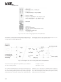
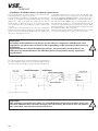
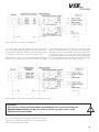
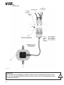
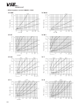
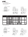
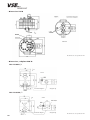
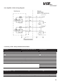
OPERATING INSTRUCTIONS
for flow meters of the product line
“Ex-Type VS“
VSE Volumentechnik GmbH
Hönnestraße 49
58809 Neuenrade Germany
Phone
+ 49 (0)2394/61630
Fax
+ 49 (0)2394/61633
email
info@vse-flow.com
Internet www.vse-flow.com
1
Table of Contents
Page
Important basic information . . . . . . . . . . . . . . . . . . . . . . . . . . . . . . . . . . . . . . . . . . . . . . . . . . . . . 3
General function description of flow meter for use in explosion-prone areas . . . . . . . . . . . . . 4
Flow meter selection . . . . . . . . . . . . . . . . . . . . . . . . . . . . . . . . . . . . . . . . . . . . . . . . . . . . . . . . . . . 4
Declaration of Conformity . . . . . . . . . . . . . . . . . . . . . . . . . . . . . . . . . . . . . . . . . . . . . . . . . . . . . . 4
General conditions for initial start-up . . . . . . . . . . . . . . . . . . . . . . . . . . . . . . . . . . . . . . . . . . . . . 4
Maximum operating pressure . . . . . . . . . . . . . . . . . . . . . . . . . . . . . . . . . . . . . . . . . . . . . . . . . . . 5
Flow meter range . . . . . . . . . . . . . . . . . . . . . . . . . . . . . . . . . . . . . . . . . . . . . . . . . . . . . . . . . . . . . 5
Installation of the flow meter . . . . . . . . . . . . . . . . . . . . . . . . . . . . . . . . . . . . . . . . . . . . . . . . . . . . 6
Cleaning and flushing of pipelines before initial start-up . . . . . . . . . . . . . . . . . . . . . . . . . . . . . . 7
Filtering of liquid . . . . . . . . . . . . . . . . . . . . . . . . . . . . . . . . . . . . . . . . . . . . . . . . . . . . . . . . . . . . . 7
Flow meters in explosion-prone environments . . . . . . . . . . . . . . . . . . . . . . . . . . . . . . . . . . . . . . 8
General information for use of devices with intrinsically safe circuits . . . . . . . . . . . . . . . . . . . . 9
VSE Ex-type flow meters. . . . . . . . . . . . . . . . . . . . . . . . . . . . . . . . . . . . . . . . . . . . . . . . . . . . . . . . 9
The isolation switch amplifier MK 13-P-Ex0/24VDC/K15 . . . . . . . . . . . . . . . . . . . . . . . . . . . . 9
Technical data of the isolation switch amplifier MK 13-P-Ex0/24VDC/K15 . . . . . . . . . . . . . 11
Installation of VSE flow meters in explosion-prone areas . . . . . . . . . . . . . . . . . . . . . . . . . . . . . 12
Safety information for installation and initial start-up in explosion-prone areas . . . . . . . . . . . 15
Maintenance and repairs . . . . . . . . . . . . . . . . . . . . . . . . . . . . . . . . . . . . . . . . . . . . . . . . . . . . . 16
Return of repairs and sample devices . . . . . . . . . . . . . . . . . . . . . . . . . . . . . . . . . . . . . . . . . . . . 16
Technical specifications VS 0.02 – VS 4 . . . . . . . . . . . . . . . . . . . . . . . . . . . . . . . . . . . . . . . . . 17
Flow response curves VS 0.02 – VS 4 . . . . . . . . . . . . . . . . . . . . . . . . . . . . . . . . . . . . . . . . . . . 18
Dimensions VS 0.02 – VS 4 . . . . . . . . . . . . . . . . . . . . . . . . . . . . . . . . . . . . . . . . . . . . . . . . . . . 19
Dimensions, subplate AP.02 - 4 . . . . . . . . . . . . . . . . . . . . . . . . . . . . . . . . . . . . . . . . . . . . . . . . . 20
Technical specifications VS 10 . . . . . . . . . . . . . . . . . . . . . . . . . . . . . . . . . . . . . . . . . . . . . . . . . 21
Flow response curves VS 10 . . . . . . . . . . . . . . . . . . . . . . . . . . . . . . . . . . . . . . . . . . . . . . . . . . . 21
Dimensions VS 10. . . . . . . . . . . . . . . . . . . . . . . . . . . . . . . . . . . . . . . . . . . . . . . . . . . . . . . . . . . . 22
Dimensions, subplate APG 10 . . . . . . . . . . . . . . . . . . . . . . . . . . . . . . . . . . . . . . . . . . . . . . . . . . 22
Type key . . . . . . . . . . . . . . . . . . . . . . . . . . . . . . . . . . . . . . . . . . . . . . . . . . . . . . . . . . . . . . . . . . . 23
Labeling of the flow meters . . . . . . . . . . . . . . . . . . . . . . . . . . . . . . . . . . . . . . . . . . . . . . . . . . . . 24
Safety data for flow meter type VS*** ******32Q1*/* . . . . . . . . . . . . . . . . . . . . . . . . . . . 24
Maximum ambient and media temperatures . . . . . . . . . . . . . . . . . . . . . . . . . . . . . . . . . . . . . . 24
Pre-amplifier – block wiring diagram . . . . . . . . . . . . . . . . . . . . . . . . . . . . . . . . . . . . . . . . . . . . 25
Summary of the safety related technical data . . . . . . . . . . . . . . . . . . . . . . . . . . . . . . . . . . . . . 25
EC-type examination certificate . . . . . . . . . . . . . . . . . . . . . . . . . . . . . . . . . . . . . . . . . . . . . . . . 26
EC declaration of conformity . . . . . . . . . . . . . . . . . . . . . . . . . . . . . . . . . . . . . . . . . . . . . . . . . . . 29
2
Important Basic Information
Dear Customers and Users,
These installation and operating instructions should convey to you the information necessary for the proper and conventional
installation and initial start-up of the flow meter in explosive areas. The installation, start-up and examination are to be carried
out exclusively by qualified and trained personnel with knowledge of the relevant national regulations for explosion protection.
These operating instructions must be read and applied carefully to ensure that the trouble-free, proper and safe operation of the
flow meter. VSE accepts no liability for damage which occurs as a result of non-compliance with the information in these operating
instructions. It is strictly forbidden to open the devices.
These operating instructions for the flow meter of the “Ex-type VS” production series must be placed where they are accessible at
all times to the authorized personnel. Chapters must never be removed from this manual. Missing operating instructions or missing
pages must be replaced immediately. VSE will supply you with new ones at any time or you can download them from the internet
(www.vse-flow.com). The operating instructions must be passed on to each subsequent user of this product.
Legal References
This document is not subject to the revision service through the VSE Volumentechnik GmbH.
Revisions can be made on this document without further announcement.
The VSE Volumentechnik GmbH issues not tacit guarantees for customary quality and suitability for a certain purpose.
After the arbitrary opening or alteration of the device or after a singular improper connection of the circuit, the ex-protection is no
longer applicable and thus the guarantee and warranty of the VSE Volumentechnik GmbH for safe operation in explosive areas
is also no longer applicable. VSE Volumentechnik GmbH assumes no liability whatsoever for personal or material damage which
occurs as a result of improper installation and improper operation of the flow meter.
Operating manual – No.: E060034 ( E )
Date: 31.05.2006
3
• General function description of flow meter for use in explosion-prone areas
VS positive displacement flowmeters are volume rate measuring sensors
based on the meshing gear principle and are designed for use with liquids.
Two precisely matched gear wheels are enclosed in a very accurately machined housing. Gear rotation is sensed by a non-contacting signal pick-up
system. Each tooth produces one impulse. The space between the gear
teeth, when fully enclosed on both sides by the housing, constitute measuring chambers. Fluid flow causes the gears to rotate and the incoming flow
is separated into discrete volumes within these chambers i. e. the volume of
liquid passing through the unit will cause rotation of the gears by exactly
one tooth pitch. This volume is known as the Volume / Impulse (Vm) and is
stated in cc/Imp. It is used to define the size of a flowmeter.
The ex-type flow meters of the production series “VS” are used in explosionprone areas. The pre-amplifier of this “Ex-type” supplies two modulated
digital current signals which are staggered at 90° to one another. The
frequency of these signals is proportional to the current flow.
These separate switching currents are digitalized and amplified by two
single-channel isolation switching amplifiers.
• Flow meter selection
For trouble-free and safe operation of the flowmeters the correct
selection of type and size is imperative. Due to the great number of
different applications and flowmeter versions, the technical data in
the VSE-catalogues are of general character. Certain characteristics
of the devices depend on type, size and measuring range as well as
on the medium to be measured. For exact flowmeter choice, please
contact VSE.
• Declaration of Conformity
Flow meters of the “VS” product line for explosion-prone areas are tested for their electromagnetic compatibility and interference transmission in
terms of the law on electro-magnetic compatibility and correspond to the
legal prescriptions enforced by EMC directives. They may not be operated
independently they are to be connected via cable to a power source and
supply digital electric signals for electronic evaluation.
The electromagnetic compatibility of the total measuring sys-tem
depends on cable layout, correct connection of protective shielding
and each single connected device, user ensure that all components
correspond to the electromagnetic compatibility directives and that
the electromagnetic compatibility of the total system, machine or
plant is guaranteed.
All flow meters are tested according to the valid, legally prescribed electromagnetic compatibility directives EN 55011 and EN 61000.
Ex-type “VS” flow meters are approved for use in explosive areas and fulfill
the basic safety and health requirements for the design and construction of
devices and protective systems in accordance with the guideline 94/9/EC
(ATEX 95).
Through their compliance with the European norms EN 50014, EN 50020
and EN 50284, the devices fulfill these safety and health requirements
and have been certified by an accredited admissions agency. An EC-type
examination certificate is on page 26. The EC declaration of conformity is
the CE label attached to all flow meters.
All flow meters are designed in accordance with the valid statutory regulations.
• General conditions for initial start-up
Before assembly and before initial start-up, you have to note the following
properties and aspects of the corresponding characteristics of your system,
so that a trouble-free and safe operation is possible.
1. The process fluid
‹
Is the flow meter suitable for the fluid?
‹
Is the fluid viscous or abrasive?
‹
Is the fluid contaminated or is there solid matter in the fluid?
‹
Which granular size does the solid matter possess and can it block the meter?
‹
Does the fluid have fillers or other additional material?
‹
Is it necessary to install a pre-switched hydraulic filter?
‹
Are the pipe lines clean and free of assembly residues such as swarf, weld chips?
‹
Is the tank clean and is it ensured that no extraneous materials can get into the pipe-line system from the tank?
‹
Is the fluid often changed and is sufficient flushing performed in this case?
‹
Are the pipe lines and the entire system completely de-aerated?
‹
What cleaning agent is being used?
‹
Are the fluid and the cleaning agent compatible with the seals?
‹
Are the seals suitable for the fluid undergoing measurement (seal compatibility)?
4
2. The hydraulic properties of the system
‹
Is the max. operating pressure of the system lower than the max. permitted operating pressure of the flow meter?
‹
Is the max. pressure drop ∆p (on flow meter) below the max. permitted pressure drop?
‹
Does an excessively great drop in pressure ∆p occur on the flow meter at max. flow (e.g. with higher viscosity)?
‹
Does the flow range of the flow meter (depending on viscosity) correspond to the provided flow?
‹
Note that flow range decreases the greater the viscosity!
‹
Does the temperature range of the flow meter correspond to the provided max. temperature of the medium?
‹
Is the cross section of the pipe line large enough and are the pressure drops in the system not excessive?
‹
Is the hydraulic connection (supply and reverse flow) correctly connected and leak-proof?
‹
Has the pump sufficient power to operate the system?
‹
A blocking flow meter can stop the whole flow. Is a pressure control valve / bypass provided in the system?
3. Electronic evaluation and electrical safety
‹
Have you selected the optimal flow meter and is this equipped with the appropriate pre-amplifier?
‹
Does the power supply voltage of the flow meter correspond to the provided voltage?
‹
Is the power supply voltage supplied by the power adapter or evalution unit sufficiently steady?
‹
Does the output of the power supply voltage correspond to the required power output?
‹
Has the electric connection been installed based on the enclosed connection plan?
‹
Is the flow meter connected securely to the earth conductor PE?
‹
Is the meter of the flow meter constructed to be insulated to the earth conductor PE (e.g. connection via hoses)? If this is the case, the meter
has to be connected with the earth conductor PE!
‹
Does a correcting lead have to be laid to eliminate the potential difference between the flow meter and the receiver?
‹
It must be ensured to the highest extent that potential equalization exists for the entire system.
‹
Is the cable laid fault-free and the installation secured from input of interference pulses?
‹
Is the 4-pin round plug of the connection cable firmly screwed together with the plug of the flow meter?
‹
Are the wires on the evalution unit and the switching amplifiers correctly and properly connected?
‹
Does the entire system correspond to the directives of the electro-magnetic compatibility laws (EMC)?
‹
Have all local valid regulations, applicable directives, guidelines and background conditions of the electro-magnetic compatibility laws
been maintained and observed?
‹
Were all legal regulations and guidelines for ex-protection observed during the installation of the flow meters and other system
components?
‹
Systems that can lead to personal injury through malfunction or failure are to be equipped with the appropriate safety devices. The functioning of these safety devices is to be checked at regular intervals.
• Maximum operating pressure
Before assembling the flow meter, you must check that the max. operating
pressure of the system does not exceed the max. permitted operating pressure of the flow meter. In the process observe the highest pressures that can
occur when operating the system.
The following operating pressures are permitted depending on flow meter
‹ Flow meter in grey cast iron version
‹ Flow meter in stainless steel version
‹ Flow meter in special version
pmax = 315 bar / 4568 psi
pmax = 450 bar / 6526 psi
pmax = up to 700 bar / 10150 psi
Important:
Please consult VSE for all operating pressures > 450 bar and for special versions.
• Flow meter range
The flow meter range specified in the flow meter data sheet (Qmin - Qmax)
refers to the testing fluid hydraulic oil with a viscosity of 21 mm2/s at a
temperature of 20 °C. For this flow meter range, VSE specifies measurement accuracy of up to 0.3 % of the measurement value and a repetition
accuracy of 0.05 %.
For fluids of lower viscosity (< 21 mm2/s) measurement accuracy deteriorates, while for fluids of higher viscosity (> 21 mm2/s) it can improve. The
higher the viscosity, the higher the flow resistance ∆P. Also note, however,
that the flow meter range is restricted in case of higher viscosity (see flow
meter data sheet).
5
Important:
Make sure that the specified maximum permitted operating pressure of the flow meter
cannot be exceeded, at any operating mode of the system. Note the flow meter range
that is dependent on the viscosity of the fluid to be measured.
• Installation of the flow meter
The flow meter should be mounted on an easily accessible location, so that
it can be removed easily for cleaning.
Since flow meters can work in any installation position and flow direction,
you can mount it on any location of your system that you wish. Take care
when installing the flow meter that liquid always remains in the flow meter
even at system standstill and that it can never run empty.
The outflow of the flow meter should therefore always show a certain back
pressure. In critical cases or when the pipe line is at standstill or standby
and can run empty, we recommend installing an extra non-return valve in
the outflow line.
non-return valve
flow meter
tank
Fig. 1: Flow meter installation with non-return valve
Important:
Make sure that the flow meter is always completely filled both in inflow and outflow and
that the outflow has a little back pressure. This prevents the meter being damaged by a
sudden and steep increase of flow and at the same time improves measurement accuracy.
Flow meters of the “VS” product line can be mounted directly onto a block
or into the pipeline using four screws. Always select large cross sections
for the hydraulic supply and return flow respectively for the entire pipeline
system (if possible). This lowers the drop in pressure and the flow rate in
the overall system.
VSE supplies subplates for all flow meters of the “VS” product line; they
have various pipe threads and side or rear-side connection (see subplates
data sheet). Depending on the provided conditions, the installed pipe line,
the pipe cross section or pipe thread, the operator can choose the suitable
subplate and incorporate this into the system or machine without additional
reductions.
The flow meter is screwed onto the block or subplate with four DIN 912
cheese head screws. The screws are to be pre-tensed crosswise evenly with
the following torques.
6
‹
Block assembly:
The flow meter is directly mounted onto a subplate. The subplate
is installed in the pipeline, is attached with four screws to a
mounting panel, console or device wall, and has all the necessary
hydraulic connections and screw holes for mounting the flow
meter.
Table 1: Torque of fastening screws
Flow meter, size
(cast iron and 1.4305)
Torque
VS 0.02; VS 0.04; VS 0.1; VS 0.2
40 Nm
VS 0.4; VS 1; VS 2
70 Nm
VS 4
120 Nm
VS 10
280 Nm
Please note the special instructions for mounting sizes VS 4 and VS 10
(see appendix)
Important:
When mounting the flow meter, you must take great care that the seals are not damaged
and correctly placed in the hydraulic connections of the flow meter. Wrongly installed or
damaged seals lead to leakage and to an leaky system, which may have dire consequences.
Please make sure that flow meters with EPDM seals do not come into contact with oil and
greases on a mineral oil basis. These fluids can decompose the seals.
The yellow plastic plugs in the hydraulic connections of the flow meter protect the meter
against dirt and contamination during storage and shipping. Before mounting the flow
meter you have to remove these plugs so that inflow and outflow are free and open.
• Cleaning and flushing of pipe lines before initial start-up
Before initial start-up of the flow meter, you must flush and clean the whole system. Contaminated fluids can affect the correct function of the flow
meter or seriously damage the meter.
After preparing and connecting up the system pipes, you must first carefully
flush and clean the whole pipeline system and the tank. To do this, you have
to mount a diversion plate onto the block or connection plate instead of the
flow meter, so that the fluid can flow through the diversion plate and all extraneous material (e.g. swarf, metal chips, etc.) can be flushed out without
obstruction. As a cleansing agent, use a fluid which is compatible with the
fluid being used later and which does not cause undesirable re-actions.
You can consult the suppliers and manufacturers of the fluid or contact VSE
for the corresponding information. VSE supplies bypass-plates which are
corresponding for all ”VS“-flow meter sizes.
Flow meters are measurement pick-up systems made with high-level precision. They have a mechanical meter consisting of two toothed wheels and
which is adapted to the housing with narrow slots. Even the tiniest damage
to the toothed wheels and bearings can cause a measurement error. So
always make sure that no extraneous material gets into the meter and that
the fluid flowing through is always free from dirt and contamination.
After the system has been carefully flushed out and no extraneous material
is in the pipe line, you can mount the flow meter and commence the initial
start-up.
Important:
Please flush out the pipelines and the tank thoroughly, to prevent contamination with the
flow meter.
• Filtering of liquid
Heavily contaminated fluid or extraneous material in the fluid can block,
damage or even destroy the flow meter. In such cases, always install a
sufficiently large filter in front of the flow meter to prevent damage to the
flow meter. The filtering necessary depends on size, bearing system and
model of flow meter.
Table 2: Pre-switched filters
Flow meter size
Filter size for ball bearings
VS 0.02 / 0.04 / 0.1
10 µm
VS 0.2 / 0.4
20 µm
VS 1 / 2 / 4 / 10
50 µm
For information on filter size for flow meters with plain bearings, in special
version, or with specially adjusted meter tolerances, please consult VSE
GmbH.
Important:
A blocked flow meter can stop the whole flow. You have to provide a control valve/
bypass for the system.
7
• Flow meters in explosion-prone environments
The operation of flow meters in explosion-prone environments is subject to
clearly defined legal regulations. For this reason only flow meters with a
certified ex-approval may be used in explosive areas.
For personal and material protection, the lawmakers issued national and
international standards, which have to be complied with when using
electrical components and systems in explosive atmospheres. In Europe,
the CENELEC – European Committee for Electrical Standardization – issues the harmonized standards for the explosion protection of electric equipment.
Danger of explosion can occur when handling flammable materials, i.e.
materials which can oxidize, when these materials exist as gases (e.g. methane, propane), vapors, mist or dust, their concentration in a mixture with
air lies within a certain range, and the mixture (flammable substance +
oxygen) is hazardous. With an effective source of ignition, the explosion
of these mixtures would be set off. During explosions, extremely high temperatures and a high velocity of pressure rise often occur. This could result
in people being injured, buildings and system parts being destroyed and
other flammable materials being ignited.
All electrical equipment which is installed and operated in explosion-prone
rooms or spaces must be approved for the corresponding zone and
must be equipped with a special type plate.
Explosive areas are divided into zones. The zones are divided according
to the frequency and duration of the occurrence of the hazardous explosive
atmosphere.
The division into zones is a company decision, for which the user as the
operating company must be responsible himself. The definition of zones
can be read about in the EN 1127-1 on the principles and methodology
of explosion protection. The EN 60079-10 and the example collection of
explosion protection rules (Ex-RL) provide more information on zone divisions. Technical superintendents of the trade associations can provide
assistance. But the user can always consult the ex-authority of a association
for technical inspection for zone definitions. In any case, the consent of the
industrial inspectorate must be secured.
The operation of electrical equipment and systems in explosion-prone environments is subject to clearly defined legal regulations. For this reason,
in all explosion-prone areas only flow meters with the corresponding exapproval and ex-type plate in connection with certified safety features
(associated equipment) may be used.
The Ex-type flow meters of the VSE GmbH are typed according to the
protection class ”intrinsic safety“(i) and are operated with isolation switch
amplifiers. These ensure the intrinsic safety of the signal circuits in accordance with set criteria and parameters, and their limiting values do not
exceed the maximum input values of the device. Two isolation switching
amplifiers are needed to operate an ex-type flow meter of the production
series ”VS“. They come either in two separate housings or together in one
housing.
The protection class ”intrinsic safety“(i) implies that the energy in the
circuit has to be so low, that ignitable sparks, electric arcs or temperatures
cannot occur. When installing intrinsically safe circuits, detailed regulations
must be followed. High demands are placed on the insulation in order to
avoid a voltage diversion in the ex-area. Therefore, intrinsically safe circuits always must be laid separately from circuits which are not intrinsically
safe. It is not permitted to lay cables, bunched circuits and cable harnesses
together.
The category i (Intrinsic Safety DIN EN 50020) is subdivided into:
‹
ia = intrinsically safe when two independent errors occur
‹
ib = intrinsically safe when one error occurs
The European norms basically distinguish between two equipment explosion groups. Flow meters belong to Group II (electrical equipment for
explosive areas).
Equipment in Group II is subdivided further into explosions sub-groups
and temperature classes.
‹
IIA e.g. acetone, ammonia, benzene (pure), methane, propane,
‹
IIB e.g. ethylene, town gas (illuminating gas), hydrogen sulphide
‹
IIC e.g. carbon disulphide, acetylene, hydrogen
The most hazardous substances are assigned to the Group IIC. Devices
which are approved in the Group IIC, may also be operated with substances from the Groups II A and IIB.
The approved ambient temperatures and media temperatures for the
Ex-type flow meters are determined in the corresponding temperature classes and must be strictly maintained (see page 24 „Maximum Permitted
Media and Ambient Temperatures“).
The ignition temperature (defined as the temperature at which a mixture
self-ignites in a fixed test process) is directly associated with the temperature class.
The temperature class indicates the maximum surface temperature of the
electrical equipment, and must be below the ignition temperature of the
flammable substance in order to avoid an ignition.
8
The Ex-type of the VSE flow meter is executed in the category „ia“ and is
approved for the Group IIC. Allowing for the approved media and ambient
temperatures and the installation regulations, they can be used in the zones
0, 1 and 2 (for gases and vapors).
The VSE flow meters are not approved for use in areas prone to dust explosions!
• General information for the use of devices with intrinsically safe circuits
The DIN EN 50014 contains general regulations for the type and inspection of electrical equipment intended for use in explosion-prone areas and
defines the contents of the documentation which accompanies the devices.
The national and international regulations are to be strictly observed
and complied with for specified normal operation in explosion-prone areas. Following are a few references, especially in regard to the framework directives of the European Parliament 94/9/EG (ATEX 95).
Intrinsically safe equipment may be connected to the intrinsically safe
terminals of the isolation switching amplifier. All equipment must fulfill the
requirements for operation in the existing zone of the explosive area.
When interconnecting equipment, the ”proof of intrinsic safety“ must be
documented (EN 60079-14). After connecting an intrinsically safe circuit
to a circuit which is not intrinsically safe circuit even just once, the use as
equipment with an intrinsically safe circuit is no longer permitted.
This applies to the isolation switching amplifier as well as to the flow meter.
Corresponding regulations exist for the set-up of intrinsically safe circuits,
the attachment of external connecting parts and for the properties and
laying of the wires. Wires and terminals with intrinsically safe circuits are to
be marked and separated reliably from circuits which are not intrinsically
safe (EN 60079-14).
The required distance is to be maintained from the terminals of the switching amplifier to the grounded components and terminals of other devices. Unless stated explicitly in the device instructions, the approval for the
device is terminated if it is opened for repairs or if alterations on the device
are made by someone other than a specialist or the manufacturer.
Visible changes to the housing of the isolation switching amplifier (e.g.
brown-black discolouration, holes and bulges) indicate a serious malfunction and the device must be turned off immediately. The connected flow
meter must also be checked.
Please note that only a specialist or the manufacturer may check the
explosion protection of the device.
The isolation switching amplifier may be operated only within the range of
the approved specifications printed on the housing. Before starting each
time or after changing the unit’s interconnections, it must be ensured that
the applicable provisions, regulations, guidelines and parameters are observed, that the use is as intended, and that the safety requirements have
been fulfilled.
Important:
The switching amplifier and the flow meter are to be installed and connected exclusively
by trained and qualified personnel (authorized persons) with knowledge of the relevant,
national regulations for explosion protection.
For the operating company, the guidelines ATEX 95, ATEX 137 and the
European norms EN1127-1, EN 60079-10, EN 60079-14, EN 60079-17
among others are of great importance and must be strictly applied to the
construction, installation, operation, inspection and maintenance of its system in explosive areas.
• VSE Ex-type flow meters
The VSE flow meters of the production series ”VS Ex-type“ are approved
for use in explosive areas and are always operated together with one or
two isolation switching amplifiers. They are marked in blue and afford
the necessary explosion protection safety. The type plate contains the
designations, markings, and safety and electrical data required by DIN
EN 50014 (see Page 24 ”Labelling“). VSE delivers the flow meters with
isolation switch amplifier models MK 13-P-Ex0/24VDC/K15.
• The isolation switch amplifier MK 13-P-Ex0/24VDC/K15
The isolation switch amplifier MK 13-P-Ex0/24VDC/K15 allows a galvanic transmission of binary states. It has an intrinsically safe input circuit and
is certified in accordance with II(1) GD [EExia] IIC. A galvanic isolation
exists from the input circuit to the output circuit and to the supply voltage. For the transmission from two channels, two such isolation switching
amplifiers are required. The input circuit can be monitored for discontinuity
and short circuits (the monitoring can be switched off by a wire jumper).
Although an error in the input circuit blocks the signal output, it is not emitted as an error message. Two plus switching (PNP outputs), short circuitproof transistor outputs emit a channel’s digital signal as antivalent.
9
Terminals 7,8
Power supply: 7=UB , 8 = GND (0V)
Terminals 5,6
5 = Output 1 (PNP) ; 6 = Output 2 (PNP)
LED green = Ready
LED yellow = Signal (Output 1 = Ub ; Output 2 = open)
LED off = Signal (Output 1 = open ; Output 2 = Ub)
LED red = Error (Output 1 = open ; Output 2 = open)
Label plate
Terminals 3, 4
Input circuit monitoring
(Deactivate monitoring = bridge terminals 3 and 4)
Terminals 1, 2
Intrinsically safe input circuit
1 = +Uex ; 2 = -Uex
Figure 2: View of the isolation switching amplifier MK 13-P-Ex0/24VDC/K15
The terminals 1... 4 of the isolation switching amplifier marked in blue have
electrical circuits in the ignition protection type ”Intrinsic Safety” for explosion protection in accordance with EN 50020.
The intrinsically safe circuits are certified by authorized inspection agencies and approved for use in the respective countries.
Flow meter
Transducer
Signal Output PNP
Potential bridge
for switching off
input circuit
monitoring
Power supply
Figure 3: Circuit diagram of the isolation switching amplifier MK 13-P-Ex0/24VDC/K15
The flow meter delivers a digital current signal which is processed further in
the isolation switching amplifier.
Since signals are transmitted by means of an imposed current signal, only
two wires are needed for the transmission cable. From the current signal,
the isolation switching amplifier generates the plus switching output signal
(PNP signal) and the inverted plus switching output signal (PNP signal).
10
Low Signal = < 2.7 mA
High Signal = > 3.7 mA
Usually the receiver only requires the standard generated signal (see
Figure 3 and Figure 4), the inverted signal is processed only in exceptional
cases. In the circuit diagrams, therefore, the inverted signal is shown only
dashed. Therefore the inverted signal is.
One volume measurement
= 1 Vm
Signal
Inverted signal
Figure 4: Signal output of the isolation switching amplifier
Note:
Please note that the signal output of the isolation switching amplifier is a PNP signal (low
signal = open output; high Signal = Ub). If the evalution unit has high-impedance inputs, this
could cause problems, especially at higher flow rates. The signal flanks slur and the analysing unit can no longer recognize digital signals. In this case, connect a pull-down resistor of
approx. 2.2 ... 4.7 k Ω parallel to the input of the evalution unit (see Figure 3 resistor R).
If the ”wire jumper for input circuit monitoring“ (see Figure 3) is switched,
the monitoring is disabled.
• Technical data for isolation switching amplifier MK 13-P-Ex0/24VDC/K15
Manufacturer
Werner Turck GmbH & Co. KG
Type Designation
MK13-P-Ex0/24VDC/K15
Operating voltage
Ripple WSS
Power consumption
Galvanic isolation
10 ... 30V DC
≤ 10 %
approx. 20mA
input circuit to input circuit
and supply voltage
for 250Veff
2.5kVeff
Test voltage
Input circuit
Rating
- Open circuit voltage U0
- No-load current I0
- Internal resistance Ri
Switch points
Discontinuity threshold
Short-circuit threshold
Output circuits
Line voltage drop
Switching current per output
Switching frequency
Ex-approval according to
conf.- certificate
Maximum values
- Open circuit voltage U0
- Short-circuit current I0
- Output P0
External inductivity/capacity L0 / C0
- [EEx ia] IIB
- [EEx ia] IIC
Temperature range TU
Designation of the device
2/10/20mH / 5/3.5/3µF
1/5/10mH / 1.1/0.75/0.65µF
-25 ... +70 °C
II (1) GD [EEx ia] IIC
LED displays
- Status / error alarm
- Ready
yellow / red (two-colour LED)
green
Terminal box
intinsically safe as per EN 50020
8.2V
16.4mA
≤ 500Ω
2.9 ... 3.5mA (± 0.2mA)
≤ 0.16mA
≤ 12.4mA
two transistor outputs, short-circuitproof, plus switching
≤ 2.5V
≤ 100mA
≤ 3kHz
Dimensions
Connection
Connection cross-section
Protection class
Operating temperature range
8- pole, polycarbonate / ABS
Combustibility class V-0 according
to UL94 can be snapped onto DIN
rail (DIN 50022) or snapped onto
subplate
Height: 89mm, Length: 70mm,
Width: 18mm
Flat terminals with self-lifting
pressure disc
≤ 2 x 2.5mm2 oder 2 x 1.5mm2
with wire end sleeves
(IEC 60529 / EN60529) IP20
-25 ... +70 °C
PTB 06 ATEX 2025
≤ 9.9V
≤ 22mA
≤ 54mW
11
• Installation of VSE flow meters in explosion-prone areas
The following illustrations show three examples of the connection of flow
meters intended for use in explosion-prone areas.
Select the example most suitable for your application and connect the individual pieces of equipment according to the illustrations shown. Switching
amplifiers also contain circuits which are not intrinsically safe and must
not be installed in explosion-prone areas. The electrical circuits which
are not intrinsically safe are to be installed in accordance with DIN VDE
0100-410.
In explosion-prone areas, the flow meters are connected to a system which
has been grounded according to regulations. For safe EMC operation, VSE
supplies a connecting cable with the shield bearing on the coupling nut of
the four-pole circular plug-in connector.
For safe EMC operation it is not necessary to also connect the shield earth
potential at the other end of the connecting wire. You must always make
sure that the potential equalization system is connected properly to
ensure that no difference in potential can occur between the connections of the earth conductor PE (flow meter >> switching amplifier >> electron. evaluation). For this purpose, connect an additional wire (ca. Ø 4.. Ø
6 mm2) between the individual pieces of equipment (see PE arrows in the
following illustrations) or connect the individual PE connecting points radial
at a certain point with the earth conductor PE.
Connection can be made to the housing of the measuring device, to which
a conductor with a minimum cross-section of 4mm2 is to be made.
Important:
Assembly and installation must always be carried out in compliance with the local valid
regulations, the observance of which is the responsibility of the operator of the measuring
equipment.
All installations must meet the EMC requirements. You must make sure that there is no
difference in potential between the individual pieces of equipment and lay a potential
equalisation!
The connection diagram Figure 5 shows the evaluation of a signal from the
flow meter. With this measuring system you can determine the flow rate and
the volume, but the direction of flow cannot be determined with this circuit.
Figure 5: Evaluation of one channel
Important:
This evalution unit can be used when it is ensured that the volume flow can flow in only one
direction. When the flow direction changes (also short term), the receiver does not perceive
this return flow, and a measurement error occurs.
12
Figure 6: Evaluation of two channels (standard circuit)
As a rule, this circuit is used as the standard. The electronic evalution unit
processes the digital signals from channels 1 and 2 and supplies the current. The inverted signals of the channels are not required for the evaluation so that they are omitted, and you only need a four-strand cable.
With the Figure 7 circuit, you can create two autarchic functioning signal
systems. This type of flow meter has two galvanic isolated circuits which
operate separately, thus allowing a separate processing of the signals
(channel 1 and channel 2). As you can see in Figure 7, the signals are transmitted through isolation switching amplifiers which operate separately. The
two systems are fed by two sources of power. Since the two signal systems
are galvanically isolated from one another and operate independently, this
type is used in equipment and systems which operate redundantly. Even if
one of the signal systems fails, the other continues to function.
Figure 7: Galvanic isolation between the channels through separate power supply
Important:
The isolation switching amplifier MK13-P-Ex0/24VDC/K15 is manufactured by the
WERNER TURCK GmbH & Co. KG exclusively for the Ex-type flow meters of the
VSE Volumentechnik GmbH!
The connection diagram in Figure 6 shows the evaluation of two channels
of the flow meter. With this measuring system, you can measure the flow
rate and volume in both directions of flow.
13
Brown
Figure 8: Measurement in explosive areas
Important:
Persons who are assigned to assemble, put into service and operate the devices must
be correspondingly qualified for the tasks and, in particular, be knowledgeable about
explosion protection.
14
• Safety information for installation and initial start-up in explosion-prone areas
• The set-up of Ex-systems is to be carried out strictly by qualified
personnel only, i.e. by an authorized person with explosion protection training!
always be operated with isolation switching amplifiers which
guarantee the intrinsic safety and are Ex-certified. They are marked in
blue and offer the necessary explosion protection safety!
• The qualified personnel must have observed and understood the
corresponding EC-type examination certificates and EC declarations
of conformity!
• The isolation switching amplifiers must ensure that that the intrinsic
safety of the signal current is at the „ia“ (DIN EN 50020) protective
level und their limiting values must not exceed the maximum approved
input values of the flow meter!
• Work on the devices is to be carried out strictly in a dead voltage
state!
• Before the initial start up of the flow meters, the entire system must be
carefully flushed and cleaned so that no extraneous material left over
from the installation can get into the flow meter!
• The pipelines and the flow meter must always be filled during operation so that no gas bubbles can form!
• Heavily contaminated fluid or extraneous material in the fluid can
block, damage or even destroy the flow meter. In such cases, always
install a sufficiently rated filter in front of the flow meter to prevent
damage to the flow meter!
• VSE ex-type flow meters are not approved for areas prone to dust
explosions!
• In order to suppress inductive interference, a connecting cable with
the shield bearing on the coupling nut of the four-pole circular plug-in
connector must be used during the installation of the flow meter. In
explosion-prone areas the flow meter is connected to the ground
potential. The greatest care must be taken to ensure that between
each end of the electrical circuit (i.e. between the explosive area
and the non-explosive area) potential equalisation exists. The potential
equalisation of the ground conductor PE must be present wherever
the intrinsically safe electrical circuit is created!
• The operator must keep the system in proper condition, operate it,
constantly monitor it, and carry out necessary repair work on it immediately while taking the required safety measures. This process
known as constant monitoring should be adopted in conformance
with European legislation!
• For the use of flow meters of the „VS“ production series in explosioprone areas, VSE supplies specialised flow meters.
These flow meters are approved for use in explosive areas and must
• After connecting an intrinsically safe circuit to a circuit which is not
intrinsically safe circuit even just once, the use as equipment with an
intrinsically safe circuit it is no longer permitted. This applies to the
isolationswitching amplifier as well as to the flow meter. Corresponding regulations exist for the set-up of intrinsically safe circuits, the
attachment of external connecting parts and for the properties and
laying of the wires. Wires and terminals with intrinsically safe circuits
are to be marked and separated reliably from circuits which are not
intrinsically safe (EN 60079-14)!
• The sum of the maximum effective capacity Ci and inductance Li of
the flow meter and the four-pole connecting cable must not exceed
the maximum values C0 and L0 of the associated switching amplifier.
Pay attention also to the manufacturer’s instructions for the connecting cable and the length of wire used!
• Whenever the flow meters are in operation, the approved ambient
and media temperatures in the corresponding temperature classes
must not be exceeded!
• When starting up or performing repairs on the flow meter, the housing
must be well protected against bumps and sharp edges, tools or other
such situations!
• The pre-amplifier housing is made of die cast aluminium. Bumping
and rubbing, especially between aluminium and steel, must be avoided so that no sparks are generated!
• When using the flow meter (VS Ex-type) in areas which require category 1 equipment, the sensor must be set up so that sparks from
bumping and rubbing eliminated!
• No changes or expansions may be made to the devices if not
explicitly allowed y the manufacturer. If the housing of the pre-amplifier
is opened, the explosion protection is cancelled!
15
• Maintenance and repairs
VSE flow meters are basically maintenance-free. Nevertheless it’s advisable to return the
flow meters to the factory for regular inspections, especially when they are used in
extreme situations or with critical media (e.g. abrasive, soiled media or media with fillers or
pigments), high viscosity and very high loads on the meter (e.g. frequent and rapidly
changing flows). At the factory, any minor damage can be detected and repaired at an early
stage before it leads to a complete failure of the flow meter, whether due to a defective
bearing or due to a blocking of the meter.
The operator is responsible for regular checks, maintenance and recalibration. Any observed
defect or damage prohibits the further use!
Repairs are to be made by the manufacturer or authorized personnel only. Any other repairs
must be examined by a specialist.
• Return of repairs and sample devices
It is imperative that you enclose an exact description of the complaint, objection or fault when returning the device to ensure a rapid and eco-nomic
repair of the flow meters and other components. Furthermore, you must include a material safety data sheet (MSDS), which informs unambiguously
which fluid was run with the flow meter and how dangerous this fluid is.
The maintenance of legal regulations as regards work safety, such as workplace regulations, accident prevention regulations, and stipulations on environmental protection, waste disposal and the water management law,
obliges industrial corporations to protect their employees and other persons and environment against harmful effects when handling hazardous
16
materials. If further safety precautions are still necessary despite careful
emptying and cleaning of the flow meter, information on this is imperative
and must be included with the returned despatch.
When returning flow meters to VSE Volumentechnik GmbH, please note
that inspection and repair will only be performed if the safety specifications sheet of the utilised medium is enclosed and the flow meters completely cleaned and flushed. This protects our employees and simplifies
our work.
Non-compliance will result in a return at your expense!
• Technische Daten VS0.02 – VS4
Size
Measuring range
l/min
Frequency
Hz
Pulse value
cm3/pulse
K-factor
pulse/litre
VS 0.02
0.002 … 2
1.667 … 1666.67
0.02
50 000
VS 0.04
0.004 … 4
1.667 … 1666.67
0.04
25 000
VS 0.1
0.01 … 10
1.667 … 1666.67
0.1
10 000
VS 0.2
0.02 … 18
1.667 … 1500.00
0.2
5 000
VS 0.4
0.03 … 40
1.250 … 1666.67
0.4
2 500
VS 1
0.05 … 80
0.833 … 1333.33
1
1 000
VS 2
0.1 … 120
0.833 … 1000.00
2
500
VS 4
1.0 … 250
4.167 … 1041.67
4
250
Accuracy
: up to 0.3 % of measurement value (with viscosity > 20mm2/s)
Repeatability
: ± 0.05 % under the same operating conditions
Material
: Cast iron EN-GJS-400-15 (EN 1563) or
stainless steel 1.4305
Meter bearing
: Ball bearings or steel plain bearings (medium-dependent)
Seals
: FPM (standard), NBR, PTFE or EPDM
Max. operating pressure
: Cast iron EN-GJS-400-15 (EN 1563)
stainless steel 1.4305
Viscosity range
: 1 … 100 000 mm2/s
Installation position
: unrestricted
Flow direction
: unrestricted
Running noise
: max. 72 db(A)
Channel offset
: 90° ± 30° max.
Pulse-width repetition rate
: 1/1
Pre-amplifier housing
: Aluminum
Protection type
: IP 65
315 bar / 4568 psi
450 bar / 6526 psi
± 15° max.
17
18
Flow resistance ∆ p
Flow resistance ∆ p
Flow resistance ∆ p
Flow resistance ∆ p
Flow resistance ∆ p
Flow resistance ∆ p
Flow resistance ∆ p
Flow resistance ∆ p
• Flow response curves VS 0.02 – VS 4
VS 0.02
VS 0.04
Flow Q
VS 0.1
VS 0.4
VS 2
Flow Q
Flow Q
VS 0.2
Flow Q
Flow Q
VS 1
Flow Q
Flow Q
VS 4
Flow Q
• Dimensions VS 0.02 – VS 4
Centering bore hole
Centering bore hole
size
A
B
C
D
E
øG
H
K
L
M
N
O-ring
weight
GCI
E
kg
kg
0.02
100
80
91
M6
12.5
9
114
58
70
40
20
11 x 2
2.8
3.4
0.04
100
80
92
M6
11.5
9
115
59
70
40
20
11 x 2
2.8
3.4
0.1
100
80
94
M6
9
9
117
61
70
40
20
11 x 2
2.8
3.4
0.2
100
80
94
M6
9.5
9
117
61
70
40
20
11 x 2
3.0
3.7
0.4
115
90
96.5
M8
11.5
16
120
63.5
80
38
34
17.96 x 2.62
4.0
5.0
1
130
100
101
M8
12.5
16
124
68
84
72
34
17.96 x 2.62
5.3
6.8
2
130
100
118
M8
15
16
141
85
84
72
34
17.96 x 2.62
6.7
8.4
4
180
140
145
M12
20
30
168
110
46
95
45
36.17 x 2.62
14.7
18.4
VS
The dimensions are specified in mm
19
• Dimensions, subplates AP.02 - 4
Connection position, side
Flow meter
Subplate
For size
VS
Connection
thread
G
0.02
0.04
0.1
0.2
G 1/4“
0.4
1
2
4
G 3/8“
F
35
G 1/2“
23
B
C
D
35
28
G 3/4“
40
33
G 1/2“
35
28
G 3/4“
40
33
G 1“
55
41
G 1 1/4“
70
51
*G 1 1/2“
70
G 1 1/2“
80
Connection position below
Flow meter
56
E
L
Thread /depth
M
weight
kg
100
M6 / 12
1.8
115
M8 /15
2.7
130
M8 /15
3.6
26
80
90
40
70
28
G 1/2“
Subplate
A
20
*only for AP. 4 U...
20
øH
30
38
90
100
38
80
100
110
72
84
46
52
46
52
55
120
140
110
130
100
120
110
60
72
M8 /15
180
7.4
12.0
• Technical specifications VS 10
Size
Measuring range
l/min
Frequency
Hz
Pulse value
cm3/pulse
R-factor
pulse/litre
VS 10
1.5 … 525
7.50 … 2625.00
3.333
300
Accuracy
: up to 0.3 % of measurement value (with viscosity > 20mm2/s)
Repeatability
: ± 0.05 % under the same operating conditions
Material
: Cast iron EN-GJS-600-3 (EN 1563)
Meter bearing
: Ball bearings or steel plain bearings (medium-dependent)
Weight
: 70 kg without connection plate
Seals
: FPM (standard), NBR, PTFE or EPDM
Max. operating pressure
: 350 bar / 5000psi
Viscosity range
: 5 ……100 000 mm2/s
Installation position
: unrestricted
Flow direction
: unrestricted
Running noise
: <80 db(A)
Channel offset
: 90° ± 30° max.
Pulse-width repetition rate
: 1/1
Pre-amplifier housing
: Aluminum
Protection type
: IP 65
± 15° max.
• Flow response curves VS 10
21
• Dimensions VS 10
The dimensions are specified in mm
• Dimensions, subplate APG 10
APG 10 SG0N / 1
View X
Connection diagram
Weight 21 kg
APG 10 SW0N / 1
View X
M16-27 Depth
Connection diagram
22
Weight 30 kg
The dimensions are specified in mm
• Type key
Flow meters VS Ex-type
Subplates AP
23
• Labelling of the flow meter
VSE Volumentechnik GmbH
Hönnestraße 47
58809 Neuenrade / Germany
Name and address of the manufacturer:
0158
CE label:
VS *** ******-32Q1*/*
Type designation :
Compliance with directive 94/9/EC compliance
II 1G EEx ia IIC T6...T4
Type plate:
• Safety data for flow meter type VS *** ******-32Q1 */*
Nominal values:
Nominal voltage
Switching current
VCC1,2 = 5...10V
ILow1,2 < 2.7mA
IHigh1,2 > 3.7mA
(ILow min1,2 > 2.0mA)
(Ihigh max1,2 < 4.5mA)
Maximum values
Ui
Ii
Pi
Ci
Li
Ri
= 18.5V
= 24 mA
= 100mW
= 0.27µF
=0
=0
• Maximum ambient and media temperatures
Temperature class
T4
T5
T6
Ambient temperature
-20°C (-4°F) ≤ Tamb ≤ 95°C (203°F)
-20°C (-4°F) ≤ Tamb ≤ 70°C (158°F)
-20°C (-4°F) ≤ Tamb ≤ 55°C (131°F)
Media temperature
-20°C (-4°F) ≤ TMed ≤ 100°C (212°F)
-20°C (-4°F) ≤ TMed ≤ 75°C (167°F)
-20°C (-4°F) ≤ TMed ≤ 60°C (140°F)
24
• Pre-amplifier - block wiring diagram
• Summary of the safety-related technical data
Flow meter
VSE connecting cable, blue RAL 5015
Switching amplifier
Type: VS *** ******-32Q1*/*
shielded; 4x 0.34 mm2
Type: MK13-P-Ex0/24VDC/K15
BVS 05 ATEX E 071 X
PUR
PTB 06ATEX 2025
II 1G EEx ia IIC T4-T6
II (1) G [EEx ia] IIC
Ui = 18.5 V
R = 0.053 Ω/m
Ii = 24 mA
L = 0.85 µH/m
(x)
Uo = 9.9 V
Io = 22 mA
Pi = 100 mW
CA-A = 55 pF/m
(x)
Po = 54 mW
Ri = 0
CA-S = 105 pF/m
(x)
Li = 0
[(x) = measured at 1000Hz]
IIC
Ci = 0.27 µF
IIB
Lo/mH
1
5
10
Co/µF
1.1
0.75 0.65
2
10
20
5
3.5 3
Temperature class
T4
T5
T6
Ambient temperature
-20°C (-4°F) ≤ Tamb ≤ 95°C (203°F)
-20°C (-4°F) ≤ Tamb ≤ 70°C (158°F)
-20°C (-4°F) ≤ Tamb ≤ 55°C (131°F)
Media temperature
-20°C (-4°F) ≤ TMed ≤ 100°C (212°F)
-20°C (-4°F) ≤ TMed ≤ 75°C (167°F)
-20°C (-4°F) ≤ TMed ≤ 60°C (140°F)
25
26
27
28
EG-Konformitätserklärung
EC-Declaration of Conformity
CE-Déclaration de Conformité
Wir,
We,
Nous,
VSE Volumentechnik GmbH, Hönnestraße 47, 58809 Neuenrade/Germany
erklären in alleiniger Verantwortung, dass die Produkte „Volumensensor“ mit der Typenbezeichnung:
hereby declare in our sole responsibility, that the product ”volumetric sensor“ with the type codes:
déclarons de notre responsabilité, que le produit capteur volumétric type:
VS *** ******-32Q1*/*
Anstelle der Sterne sind Buchstaben und Ziffern eingesetzt, die den
Volumensensor kennzeichnen, welche aber keinen Einfluss auf die EMV
und den Explosionsschutz haben.
Instead of stars there are insert letters and numbers, which marked the flowmeter but have no influence about the EMC and the explosion prevention.
Des lettres et des chiffres, symbolisant le capteur volumétrique, sont à mettre en lieu et place des astérisques.
Ils n`ont aucune influence sur l`EMV et la protection contre l`explosion.
auf die sich diese Erklärung bezieht, mit den folgenden Normen oder normativen Dokumenten übereinstimmt.
which is the subject of this declaration, is in conformity with the following standard or normative documents.
auquel cette declaration se rapporte, est conforme aux norme ou aux documents normatifs suivants.
Bestimmungen der Richtlinien
Terms of the directive
Prescription de la directive
Norm
Standard
Norme
94/9/EG: Geräte und Schutzsysteme zur bestimmungsmäßigen Verwendung in explosionsgefährdeten Bereichen.
94/9/EC: Equpment and protective systems intended for use in potentially
explosive atmospheres
94/9/CE: Appareils et systèmes de protection destines á êtré utilises en
atmosphéres explosibles
EN 50014:1997+A1+A2
EN 50020:2002
EN 50284:1999
EN 60079-14:1997
89/336 EWG: Elektromagnetische Verträglichkeit
89/336 EEC: Electromagnetic compatibility
89/336 CEE: Compatibilité électromagnétique
EN 61000-6-4:2001
EN 61000-6-2:2001
EG-Baumusterbescheinigung:
EC-Type Examination Certificate:
Attestatin d’examen CE de type:
BVS 05 ATEX E 071 X
Exam BBG Prüf-und Zertifizier GmbH
Dinnedahlstr. 9
44809 Bochum/Germany
Qualitätssicherung Produktion:
Production quality assessment:
Assurance Qualité Production:
BVS 06 ATEX ZQS / E 188 CE 0158
Exam BBG Prüf-und Zertifizier GmbH
Dinnedahlstr. 9
44809 Bochum/Germany
Neuenrade, den 07.07.2006
Ort und Datum der Ausstellung
Place and date of issue
Lieu et date d’établissment
Axel Vedder
Technischer Leiter
Technical Director
Directeur Technique
29
Notes
30
Notes
31
32
09/06 www.plakart.de
VSE Volumentechnik GmbH
Hönnestraße 49
58809 Neuenrade Germany
Phone
+ 49 (0)2394/61630
Fax
+ 49 (0)2394/61633
email
info@vse-flow.com
Internet www.vse-flow.com