1
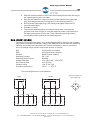
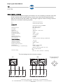
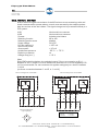
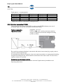
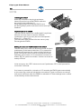
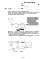
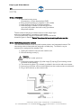
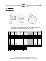
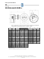
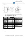
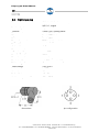
Flap-type Flow Meter KFS Installation and Operating Instructions Flap-type Flow Meter KFS KFS-IK1, KFS-IK2 KFS-RK1, KFS-RK2 KFS-EM KFS Ex KFS-IK1 Ex KFS-EM Ex For use of the KFS-EM device in hazardous areas, refer to the "Supplementary installation and operating instructions - flap-type flow meter KFS-EM EEx“. A. Kirchner & Tochter GmbH Dieselstraße 17 · D-47228 Duisburg Fon: +49 2065 9609-0 · Fax: +49 2065 9609-22 Internet: www.kt-web.de · e-mail: [email protected] Version 6.0 Flap-type Flow Meter 2 KFS Contents 1. General .....................................................................................................................................................................................4 1.1. Foreword ......................................................................................................................................................................4 1.2. Exemption from liability ..........................................................................................................................................4 2. Safety.........................................................................................................................................................................................4 2.1. Symbol and meaning...............................................................................................................................................4 2.2. General safety directions ......................................................................................................................................4 2.3...................................................................................................................................................................................................4 2.4. Intended use ...............................................................................................................................................................4 2.5. Information for Operator and operating personnel..................................................................................5 2.6. Regulations and directives ...................................................................................................................................5 2.7. Compliance with the IP degree of protection ..............................................................................................5 2.8. Use of devices of explosion-protected design..............................................................................................5 2.9. Notice as required by the hazardous materials directive......................................................................6 3. Transport and storage......................................................................................................................................................6 4. Measuring principle of the flap-type flow meter ....................................................................................................6 5. 6 6. Installation, start-up and maintenance of the mechanical part .....................................................................7 6.1. Preparatory work .....................................................................................................................................................7 6.2. Installation of the KFS.............................................................................................................................................7 6.3...................................................................................................................................................................................................7 6.4. Start-up .........................................................................................................................................................................7 6.5. Maintenance...............................................................................................................................................................8 6.5.1. Compliance with IP degree of protection - KFS with standard indicator part...................9 6.5.2. Setting the reference point - KFS with standard indicator part ..............................................9 6.5.3. Replacement of scale - KFS with standard indicator part..........................................................9 6.5.4. Setting the pointer reference point - KFS-EM ..................................................................................9 6.5.5. Replacement of scale - KFS-EM...........................................................................................................10 6.5.6. Removal of the indicator part from the pressurized measuring point - KFS-EM.........10 7. Installation, start-up and maintenance of devices with electrical add-on equipment........................10 7.1. Preparatory work for installation and maintenance .............................................................................10 7.2. Devices with standard indicator casing ......................................................................................................10 7.2.1. Cabling and setting the switching points of the contacts........................................................10 7.2.2. KFS-RK1, KFS-RK2 ....................................................................................................................................11 7.2.3. KFS-IK1, KFS-IK2.........................................................................................................................................12 7.2.4. KFS-IK1 with ATEX approval..................................................................................................................13 7.2.5. KFS-IKS1, KFS-IKS2..................................................................................................................................14 7.3. The indicator part EM..........................................................................................................................................15 7.3.1. Versions..........................................................................................................................................................15 7.3.2. Electrical signal output KFS-EM ...........................................................................................................15 7.3.3. Compliance with IP-degree of protection ........................................................................................ 15 7.3.4. Electrical connection KFS-EM ...............................................................................................................16 7.3.5. Self monitoring - diagnostics .................................................................................................................17 7.3.6. ESK2A as replacement ...........................................................................................................................17 7.3.7. Hart ™ communication with the ESK2A..........................................................................................19 7.4. Plug-in contact unit IK1, IK2, IKS1, IKS2.....................................................................................................20 7.4.1. Electrical connection.................................................................................................................................20 7.4.2. Setting the limit value ...............................................................................................................................22 7.4.3. Switching contact definition...................................................................................................................22 7.4.4. Technical data..............................................................................................................................................23 7.4.5. Electrical data ..............................................................................................................................................23 7.4.6. Installation......................................................................................................................................................24 7.4.7. Retrofitting a second contact...............................................................................................................24 8. Service ...................................................................................................................................................................................25 9. Disposal.................................................................................................................................................................................25 10. Technical Data ...................................................................................................................................................................26 10.1. General technical data...................................................................................................................................26 A. Kirchner & Tochter GmbH Dieselstraße 17 · D-47228 Duisburg Fon: +49 2065 9609-0 · Fax: +49 2065 9609-22 Internet: www.kt-web.de · e-mail: [email protected] Version 6.0 Flap-type Flow Meter 3 KFS 10.2. Spare parts, accessories .............................................................................................................................27 10.2.1. KFS with standard indicator part and contacts IK, IKS or RK...............................................27 10.2.2. KFS-EM ............................................................................................................................................................28 10.3. Dimensions .........................................................................................................................................................29 10.3.1. KFS Standard ...............................................................................................................................................29 10.3.2. KFS with contact (IK1, IK2, IKS1,....)...................................................................................................30 10.3.3. KFS-EM ............................................................................................................................................................31 10.4. Right angle plug ................................................................................................................................................32 10.5. Type examination certificate for KFS Ex and KFS-IK1 Ex ...............................................................33 10.6. Type examination certificate for KFS-EM Ex ........................................................................................34 10.7. 1. Addendum for KFS-EM Ex.......................................................................................................................35 10.8. 2. Addendum for KFS–EM Ex.....................................................................................................................36 10.9. DIN EN ISO 9001:2008 ...............................................................................................................................37 A. Kirchner & Tochter GmbH Dieselstraße 17 · D-47228 Duisburg Fon: +49 2065 9609-0 · Fax: +49 2065 9609-22 Internet: www.kt-web.de · e-mail: [email protected] Version 6.0 Flap-type Flow Meter 4 KFS 1. General 1.1. Foreword These Installation and Operating Instructions are applicable to devices of Series KFS. Please follow all instructions and information given for installation, operation, inspection and maintenance. The Instructions form a component part of the device, and should be kept in an appropriate place accessible to the personnel in the vicinity of the location. Where various plant components are operated together, the operating instructions pertaining to the other devices should also be observed. 1.2. Exemption from liability Kirchner und Tochter accepts no liability for any damage or interruptions of operation resulting from human error, failure to comply with these Installation and Operating instructions, improper performance of installation and repair work, use of spare parts other than those from the original manufacturers or use of the KFS devices other than for the intended purpose. 2. Safety 2.1. Symbol and meaning Safety notice This safety notice can be found at all hints on work safety in these assembly and operating instructions pointing out hazards for life and limb of persons. Further, this safety notice highlights safety hints in these operating instructions that point to regulations, guidelines or operating sequences that must be observed without fail. Non-observance may result in damages to or a destruction of the flap-type flow meter and / or other parts of the installation. 2.2. General safety directions These Installation and Operating Instructions contain basic instructions for the installation, operation, inspection and maintenance of the flow meter. Failure to comply with these Instructions or improperly executed installation, wiring and repair work can lead to serious faults in the plant, giving rise to hazardous situations for "man and beast“ as well as damage to property. The operator is required to rule out potentially hazardous situations through voltage and released media energy. 2.3. Intended use The KFS devices are designed and intended for measuring the flow of compressible and incompressible fluids. They may only be installed between flanges in the pipeline. Select the KFS device model on the basis of the nominal diameter and nominal pressure at the site and also the kind of fluid product concerned; limit values are specified in the Section "Technical data" and should not be exceeded. Only devices that bear the "Ex" marking may be operated in hazardous areas. A. Kirchner & Tochter GmbH Dieselstraße 17 · D-47228 Duisburg Fon: +49 2065 9609-0 · Fax: +49 2065 9609-22 Internet: www.kt-web.de · e-mail: [email protected] Version 6.0 Flap-type Flow Meter 5 KFS 2.4. Information for Operator and operating personnel Authorized installation, operating, inspection and maintenance personnel should be suitably qualified for the jobs assigned to them, and should receive appropriate training and instruction. All persons charged with assembly, mounting, operation, inspection and maintenance duties must have read and understood the operating instructions. Gaskets in contact with the fluid product must be replaced after all maintenance and repair work. 2.5. Regulations and directives In addition to the regulations mentioned below, pay attention without fail to the notices given in Section 2.7 for operation in hazardous areas! All relevant regulations should be observed in respect of flow meter operation. These include in particular: Regulation concerning explosion protection (ExVO National, ATEX 95) Regulation concerning safe working conditions (Directive 1999/92/EC, ATEX 137) If appropriate, regulation concerning hazardous materials Accident prevention regulations Pressure Equipment Directive PED 97/23 EC 2.6. Compliance with the IP degree of protection Devices with standard indicator parts have IP66 degree of protection, while the KFSEM device has IP67 degree of protection. In the case of maintenance work involving the indicator parts, notes on maintaining the IP degree of protection are given in Sections 5.4.1, 6.1 and 0 (KFS-EM). 2.7. Use of devices of explosion-protected design The KFS, KFS-IK1 and KFS-EM flow meters are certified for use in hazardous areas Zone 1 and 2, device categories 2 and 3, atmosphere G, according to Directive 94/9/EC (ATEX 95). For such use, the regulation concerning electrical and nonelectrical devices in hazardous areas (Directive 94/9/EC, ATEX 95) is to be observed. For use of the KFS-EM device in hazardous areas, refer to the "Supplementary installation and operating instructions - flap-type flow meter KFS-EM Ex“. Due to possible static charges, the polycarbonate enclosure of the indicator part of KFS Ex and KFS-IK1 Ex devices may only be cleaned with a damp cloth. A. Kirchner & Tochter GmbH Dieselstraße 17 · D-47228 Duisburg Fon: +49 2065 9609-0 · Fax: +49 2065 9609-22 Internet: www.kt-web.de · e-mail: [email protected] Version 6.0 Flap-type Flow Meter 6 KFS 2.8. Notice as required by the hazardous materials directive In accordance with the law concerning handling of waste (critical waste) and the hazardous materials directive (general duty to protect), we would point out that all flow meters returned to Kirchner und Tochter for repair are required to be free from any and all hazardous substances (alkaline solutions, acids, solvents, etc.). Make sure that devices are thoroughly rinsed out to neutralize hazardous substances. Cavities in the KFS also have to be neutralized. For this purpose, open the neck of the KFS ring by dismantling the indicator (detach the flange connection between the KFS ring and the magnet casing). This includes the screws, Item 9 in the drawing in Section 9.2.1, and Item 15 in the drawing in Section 9.2.2). 3. Transport and storage The KFS device is packed by the factory in packaging appropriate for transportation and storage. Transport and storage should be carried out solely in the original packaging. Protect the device against rough handling, impact, jolts, etc. 4. Measuring principle of the flap-type flow meter A half-round plate, or flap, is fastened across the direction of flow to a springmounted rotating spindle in a ring that is inserted between flanges in a pipeline. As the flow rate increases, the flap rotates counter to the restoring force of the spring in the direction of flow. The ensuing angle of rotation, depending on the volume rate of flow, is transmitted via a magnetic coupling to the indicator part. A. Kirchner & Tochter GmbH Dieselstraße 17 · D-47228 Duisburg Fon: +49 2065 9609-0 · Fax: +49 2065 9609-22 Internet: www.kt-web.de · e-mail: [email protected] Version 6.0 Flap-type Flow Meter 7 KFS 5. Installation, start-up and maintenance of the mechanical part 5.1. Preparatory work Have ready flanges and fastening materials as specified in DIN EN 1092 for mounting the device between flanges. Between the flanges, include a distance of ring thickness plus 4 mm for the gaskets. Refer to assembly dimensions in Section 9.3. Check the inside diameter of your pipeline and the gaskets. Neither should be smaller than the inside diameter of the KFS. If they are, the measuring flap will jam. Straight unimpeded pipe runs upstream and downstream of the installation location should have lengths equal to 4-6 times the nominal size DN. The mounting location for control equipment should be provided downstream of the flow meter. Make sure that the flanges are in alignment and the sealing faces parallel to one another. 5.2. Installation of the KFS Generally comply with the maximum pressure and maximum temperature levels allowable for the KFS at the measuring point in your plant. The direction of flow must be the same as that indicated by the flow arrow on the device. Drain the pipelines before installing the device. Use gaskets made of rubber or SIL; for plastics devices, use only gaskets made of rubber with a Shore hardness A of approx. 65°. The gaskets should not project into the pipeline and the flow meter must be in line with the pipe axis, otherwise measurements would be falsified and/or the device could jam. Incorporating the indicator part in the equipotential bonding system in the hazardous area: The indicator part must be earthed. This can be done e.g. using a wire jumper between the flange on the indicator part and a pipe flange on the main pipeline with cable lugs appropriate for the bolted connection (not included with the flow meter!). Incorporating the indicator in the lightning protection system (if necessary). The Operator is responsible for checking and determining the scope! Tighten threaded joints for the KFS made of PVC, PP or PVDF only with max. 75 Nm; higher torques may cause the flap spindle to jam and/or the device ring to break. The device version made of PVC, PP or PVDF is not allowed to be used in hazardous areas. 5.3. Start-up Pressurize the measuring pipeline. Avoid water hammer or flow separation, as the case may be. Check the flange connections for leak-tightness and retighten bolted connections if necessary. Test the local indicator on the device with varying volumetric flow rates, starting with the maximum value. A. Kirchner & Tochter GmbH Dieselstraße 17 · D-47228 Duisburg Fon: +49 2065 9609-0 · Fax: +49 2065 9609-22 Internet: www.kt-web.de · e-mail: [email protected] Version 6.0 Flap-type Flow Meter 8 KFS 5.4. Maintenance The device is normally maintenance-free. Should it become soiled, it will need to be removed from the pipeline for cleaning. Devices fitted with contacts must be disconnected from supply and de-energized. To dismantle the device you will need the following tools: 2x open-jawed spanner, jaw span 13mm, 1x open-jawed spanner, jaw span 7mm, 1x screwdriver 4x 0.6mm, 1x socket spanner, size 7mm, up to DN 100, or 1x socket spanner, size 8mm, up to DN 250, or 1x socket spanner, size 10mm, for DN 300 and higher. Required spares: 2x gasket After dismantling, check all parts for signs of damage, corrosion, wear, etc., and replace if necessary! If necessary, wear personal protective gear (safety goggles, protective gloves, conductive footwear). Depressurize the pipe. Caution: Slacken screws/bolts only when the system has been de-energized, the pipe depressurized and free of fluid product. Drain the pipes. Remove the device from the pipeline in the reverse order as described in 5.2 . Detach the dial gauge with magnet casing from the neck of the device by removing the four M8 screws (Item 9 or 15).1 Unscrew the fastening screws (17) between spindle and flap (18). Pull the spindle together with the magnet casing and the spring assembly (13) out of the device. Clean all mechanical parts with appropriate cleaning agents. If necessary, clean the indicator part with a damp cloth that has been rinsed in soap suds and wrung out. Reassemble in the reverse order, paying special attention to the position of the flap. The bearing marked with a centre punch must point towards the spring. Do not change the original orientation of the flap (maintaining the direction of rotation appropriate to the indicator part ). The flap requires a minimum of 1 mm clearance on both sides (risk of jamming and sparking). Hazardous areas: Do not on any account remove the labelling on the scale casing containing information on explosion protection. Before switching on the supply voltage again, make sure that all parts are completely dry and have been connected up in accordance with regulations. Protect the devices from excessive dirt and extreme variations in ambient temperature. In connection with all maintenance, assembly and repair work of the flow meters, make absolutely sure that a potentially explosive atmosphere cannot occur. 1 For Item nos., see drawings in Section 9.2.1 A. Kirchner & Tochter GmbH Dieselstraße 17 · D-47228 Duisburg Fon: +49 2065 9609-0 · Fax: +49 2065 9609-22 Internet: www.kt-web.de · e-mail: [email protected] Version 6.0 Flap-type Flow Meter 9 KFS 5.4.1. Compliance with IP degree of protection - KFS with standard indicator part When carrying out assembly work on the indicators (KFS, KFS-IK1, KFS-IK2, KFS-IKS1, KFS-IKS2, KFS-RK1, KFS-RK2), and to comply with the IP degree of protection, you should wear rubber gloves or similar expedient in order to obtain a maximum torque when tightening the bayonet joint. 5.4.2. Setting the reference point - KFS with standard indicator part If, when flow is switched off, the pointer in the indicator part should not be located at the reference point, correct the reference point setting. Make all adjustments only after the flow has been switched off. You will need the following tools: open-jawed spanner, jaw span 7mm, screwdriver 4x 0.6mm. Detach the bayonet ring (1)1 from the pressure gauge casing and remove it together with the seal (3) and perspex disc (2). Lock the pointer spindle using the 7 mm open-jawed spanner, unscrew the fastening screw (4) and reset the pointer to the reference point. Reassemble the indicator in reverse order. 5.4.3. Replacement of scale - KFS with standard indicator part You will need the following tools: open-jawed spanner, jaw span 7mm, screwdriver 4x 0.6mm, socket spanner, span 5.5mm; if necessary, 1 spring washer (5)2. Detach the bayonet ring (1) from the pressure gauge casing and remove it together with the seal (3) and the perspex disc (2). Lock the pointer spindle using the 7 mm open-jawed spanner, and unscrew the fastening screw (4) and the spring washer (5). Remove the pointer (6). Unscrew the three cap nuts (7) and remove the scale (12) from the casing. To fit the new scale, proceed in the reverse order. 5.4.4. Setting the pointer reference point - KFS-EM Tools needed: 1x flat-tip screwdriver Undo the four slotted screws in the corners of the casing cover and remove the cover. With the flat-tip screwdriver, hold the pointer spindle in the "at rest" position of the indicator part und use your other hand to move the pointer against the frictional force of the pointer fastening to the point on the scale marked "Rp". Fasten the casing cover with the four slotted screws. 2 For Item nos., refer to drawings in Section 9.2.1 A. Kirchner & Tochter GmbH Dieselstraße 17 · D-47228 Duisburg Fon: +49 2065 9609-0 · Fax: +49 2065 9609-22 Internet: www.kt-web.de · e-mail: [email protected] Version 6.0 Flap-type Flow Meter 10 KFS 5.4.5. Replacement of scale - KFS-EM Tools needed: flat-tip screwdriver Undo the four slotted screws in the corners of the casing cover and remove the cover. The scale is located in 2 slots in the surrounding casing. Pull the scale sideways out of these slots in the direction of the pointer. Insert the new scale. Fasten the casing cover with the four slotted screws. 5.4.6. Removal of the indicator part from the pressurized measuring point - KFS-EM Detach the indicator part at the two brackets on the outside of the indicator casing (see note in Section 9.2.2). 6. Installation, start-up and maintenance of devices with electrical add-on equipment are described in Section 0. Installation and wiring work may only be carried out by qualified electricians. In respect of hazardous-duty equipment, the following installation standards must be observed: EN 60079-14 EN 60079-17 6.1. Preparatory work for installation and maintenance For connecting the contacts, have ready flat-tip and crosshead screwdrivers as well as tools for stripping the cables and cutting them to size. In keeping with the electrical specifications of your device, you will in addition need cable material for the connection. To maintain the IP degree of protection, only cables with outside diameters of 4.5mm - 7mm may be used in connection with the right-angle plug at the standard indicators with contacts (KFS IK1,.). The cable specifications for the KFS-EM device are given in Section 0 for indicator part EM. 6.2. Devices with standard indicator casing This includes the following devices: KFS-IK1, KFS-IK1 Ex, KFS-IK2, KFS-IKS1, KFS-IKS2, KFS-RK1 and KFS-RK2. The casing consists of a tall Polycarbonate cover, a bayonet ring and appropriate casing, and a gasket (note: IP degree of protection! Refer to Section 5.4.1). Only the KFS-IK1 Ex device may be used in the hazardous area. 6.2.1. Cabling and setting the switching points of the contacts Disconnect the cable from the mains. Remove the right-angle plug from the rear panel of the indicator. Take the plug out of the connector housing and detach the PG screwed cable gland elements. A. Kirchner & Tochter GmbH Dieselstraße 17 · D-47228 Duisburg Fon: +49 2065 9609-0 · Fax: +49 2065 9609-22 Internet: www.kt-web.de · e-mail: [email protected] Version 6.0 Flap-type Flow Meter 11 KFS Slide the individual parts of the PG screwed cable gland and the housing of the right-angle plug over the cable. Strip the insulation from the wires and connect these to the right-angle plug according to the terminal diagrams in the following sections. Remount the right-angle plug in the casing and tighten down the PG screwed cable gland. Connect to mains. The contact switching points are easy to adjust after removing the perspex hood. Use a finger to move the setpoint pointer of the switch to the appropriate point on the scale. Then check the switching point by moving the pointer beyond the set switching point. 6.2.2. KFS-RK1, KFS-RK2 The series RK signal transmitters are mechanically operating, floating reed contacts. We advise using switch protection relays of the MSR series to increase the switching capacity and reduce the capacitive load. These are available in various versions in terms of voltage supply, sensor output and number of outputs. RK1 RK2 Contact Switching function Switching performance Voltage switched Current switched Contact rating Ambient temperature Version with one switch Version with two contacts Reed Contact, floating NC / NO Bistable max.140 V AC / 200 V DC max. 0.25 A max. 5 VA, 3 W -25° C ... + 105° C Terminal assignment for reed contacts single Terminal assignment right-angle plug double 1 4 2 - 4 3 white brown black 2 3 black 1 4 3 white brown 2 blue 1 K2 blue K1 A. Kirchner & Tochter GmbH Dieselstraße 17 · D-47228 Duisburg Fon: +49 2065 9609-0 · Fax: +49 2065 9609-22 Internet: www.kt-web.de · e-mail: [email protected] Version 6.0 Flap-type Flow Meter 12 KFS 6.2.3. KFS-IK1, KFS-IK2 Series IK built-in electrical signal transmitters are non-contacting, inductive make and break contacts which operate when a control vane moved by the setpoint pointer dips into and out of the slot initiator. The change in signal is used for driving a control device via an isolation switching amplifier. IK1 IK2 Contact data Function Version with one Contact Version with two contacts Inductive slot initiator to NAMUR DIN 19233, two-wire NC or NO contact 2.0 mm 1.0% of FS ... 10.0% of FS ≤ 2.0% ≤ 10% -25°C ...+ 70°C nom. 8.2 VDC ≤ 2.5 kHz bistable 8 V DC via isolation switching amplifier KFA Switching function Slot width Hysteresis Repeat accuracy Temperature drift Ambient temperature Voltage Switching frequency Switching performance Nominal voltage Power consumption active area uncovered active area covered Ambient temperature Polarity reversal protection Certification to Inner inductance (Li) / capacitance (Ci) ≥ 2.1 mA ≤ 1.2 mA -25°C ... +70°C yes KEMA 01 ATEX 1264X 41 nF / 266 μH values for cable assemblies up to 10m II 1 G Ex ia IIC T6 Contact marking (max. U = 15V, I = 60mA, P = 100mW) i i i Terminal assignment for inductive contacts IK1 Terminal assignment right-angle plug IK2 I I I 1 4 2 3 + 4 black black 2 white 1 4 blue 3 white 2 brown 1 -- + blue -- + brown - A. Kirchner & Tochter GmbH Dieselstraße 17 · D-47228 Duisburg Fon: +49 2065 9609-0 · Fax: +49 2065 9609-22 Internet: www.kt-web.de · e-mail: [email protected] Version 6.0 3 Flap-type Flow Meter 13 KFS 6.2.4. KFS-IK1 with ATEX approval The Operator is required, as a matter of principle, to take note of the details given in the type examination certificate (TÜV ATEX 7041 X). The contact IK1 operates on the same principle as the above-mentioned signal transmitter. Devices with this contact satisfy the requirements of Directive 94/9/EC (Atex 95) and are permitted to be operated in Zone 1 hazardous areas, provided they are fed from a certified and matched intrinsically safe circuit. The allowable electrical connection data and maximum allowable ambient temperatures for operation in hazardous areas are contained in the EC-type examination certificates for Category 2G ia IIC T4..T6. For use in hazardous areas, the following measures must be taken: The indicator part must be earthed. This can be done, e.g. by using a wire jumper between the flange on the indicator part and a pipe flange on the main pipeline with cable lugs appropriate for the bolted connection (not included with the flow meter!). Use isolation switching amplifiers with appropriate type test certificates to ATEX. Suitable switching amplifiers are: KFA6-SR2-Ex1.W, supply power 230 VAC KFA5-SR2-Ex1.W, supply power 115 VAC KFD2-SR2-Ex1.W, supply power 24 VDC The bolted connections of the flanges between indicator part and flap must feature tooth lock washers on both sides. These are already mounted on delivery. The devices approved for hazardous duty feature a blue PG screwed gland at the right-angle plug for the indicator part, with integrated strain relief device. In addition, a sticker is located on the indicator with information on how to avoid electrostatic charges. Allowable media temperatures: -20°C ... +70°C -70°C .... +200°C without additional insulation measures when Operator has insulated measuring part and pipe to prevent heat up of indicator part and el. components A. Kirchner & Tochter GmbH Dieselstraße 17 · D-47228 Duisburg Fon: +49 2065 9609-0 · Fax: +49 2065 9609-22 Internet: www.kt-web.de · e-mail: [email protected] Version 6.0 Flap-type Flow Meter 14 KFS 6.2.5. KFS-IKS1, KFS-IKS2 Built-in electrical signal transmitters of the IKS series are non-contacting make and break contacts which operate when a control vane actuated by the setpoint pointer dips into and out of the slot initiator. The signal change can be processed directly in a PLC system. IKS1 IKS2 Contact Switching function Switching performance Supply voltage Current switched IA Open-circuit power consumption Ambient temperature Explosion protection Voltage drop (at Imax) Version with one contact Version with two contacts Inductive slot initiator NC or NO bistable 24 V DC 100 mA 10 mA - 25° C ... + 70° C no 1.2 V Note: Given PNP-switching devices, the switched output 3 forms a connection to 2 (+) . Between 3 and 1 a load RL must be selected so that the max. current switched (100 mA) is not exceeded. For two contacts, this applies analogously to a load RL between 1 and 4 (no direct connection between 1 and 3, or 1 and 4). Terminal assignment contact IKS 2 Terminal assignment contact IKS 1 contact 1 2 brown white black 1 brown + K1 K2 4 3 black -- 4 3 blue 2 A blue 1 + white -- contact 2 Terminal assignment right angle plug 1 blue (3) black (4) = contact 1 = contact 2 4 2 3 A. Kirchner & Tochter GmbH Dieselstraße 17 · D-47228 Duisburg Fon: +49 2065 9609-0 · Fax: +49 2065 9609-22 Internet: www.kt-web.de · e-mail: [email protected] Version 6.0 Flap-type Flow Meter 15 KFS 6.3. The indicator part EM 6.3.1. Versions KFS-EM KFS-EM EEx with electronic transmitter ESK2A 4...20 mA in 2-wire technology with electronic transmitter ESK2A 4...20 mA in 2-wire technology explosion-protected equipment according to European Standard KFS-EM-IK1 with electronic transmitter ESK2A 4...20 mA 2-wire technology and one inductive limit switch type IK KFS-EM-IK1 EEx with electronic transmitter ESK2A 4...20 mA 2-wire technology and one inductive limit switch type IK Explosion proof enclosure according to European standard KFS-EM-IK2 with electronic transmitter ESK2A 4...20 mA 2-wire technology and two inductive limit switches type IK KFS-EM-IK2 EEx with electronic transmitter ESK2A 4...20 mA 2-wire technology and two inductive limit switches type IK explosion-protected equipment according to European standard KFS-EM-IKS1 with electronic transmitter ESK2A 4...20 mA 2-wire technology and one electronic limit switch type IKS KFS-EM-IKS2 with electronic transmitter ESK2A 4...20 mA 2-wire technology and two electronic limit switches type IKS Note: For use in hazardous areas, please refer to the "Supplementary Installation and Operating Instructions - flap-type flow meter KFS-EM EEx“. 6.3.2. Electrical signal output KFS-EM The indicator part of the KFS-EM with the ESKII module supplies a current of 4 to 20 mA in two-wire connection that is proportional to the instantaneous flow rate. Transmission is force-free and hysteresis-free. The ESK2A has been factorycalibrated relative to the flow measuring range. The calibration values, used for linearization of the indicator, are stored in a memory chip (EEPROM). The required power supply is a functional extra-low voltage with safety separation (galvanic) in accordance with VDE 0100 Part 410. All instruments connected to the measuring circuit (indicators, recorders) are connected in series and together may not exceed the maximum external resistance (see data pertaining to electrical signal output). The ESK2A has polarity reversal protection. 6.3.3. Compliance with IP-degree of protection To comply with the IP degree of protection for built-in electrical equipment, please pay attention to the following: After inserting the connecting cable, tighten the cap nut on the cable gland. Close off all cable glands not used with blanking plugs . Do not kink cables directly at the cable gland. Provide a water drip point Ensure incoming cables are not subjected to mechanical loads. A. Kirchner & Tochter GmbH Dieselstraße 17 · D-47228 Duisburg Fon: +49 2065 9609-0 · Fax: +49 2065 9609-22 Internet: www.kt-web.de · e-mail: [email protected] Version 6.0 Flap-type Flow Meter 16 KFS Cable glands / screwed glands: Thread Material Cable diameter Protection* M 16x1.5 PA 5 - 10 mm IP 68 - 5 bar M 20x1.5 PA 8 - 13 mm IP 68 - 5 bar M 16x1.5 brass, nickel-pl. 5 - 9 mm IP 68 - 5 bar M 20x1.5 brass, nickel-pl. 10 - 14 mm IP 68 - 10 bar *degree of protection restricted to cable gland only Comment Standard 6.3.4. Electrical connection KFS-EM The connection terminals of the ESK2A module in the KFS-EM indicator part are of the plug-in type and can be removed to connect the cables. Terminal connection Type of connection pluggable; < 2,5 mm2 2 wire current sink - polarity reversal protection only for connection to extra-low voltage according to SELV or PELV ESK2A Be careful by conceptual design in connection with other instruments (e.g. supply units or process control engineering). It is possible that internal connection of ground, earth-connections or equipotential bonding will generate voltage drops, which leads to malfunction of the instrument. For this case a signal processor is required. Connections at hazardous locations Before installation at hazardous location read the Supplementary Installation and Operating Instruction. A. Kirchner & Tochter GmbH Dieselstraße 17 · D-47228 Duisburg Fon: +49 2065 9609-0 · Fax: +49 2065 9609-22 Internet: www.kt-web.de · e-mail: [email protected] Version 6.0 Flap-type Flow Meter 17 KFS 6.3.5. Technical data ESK2A Power supply Measuring signal Supply power influence Ext. resistance dependence Temperature influence max. external resistance / load impedance Ambient temperature 24 V DC 4 to 20 mA for 0 to 100% flow value > 20.8 mA for alarm status < 0.1% < 0.1% < 5 μA / K 0 (250 *) to 800 ohm -25°C ... + 60°C * With HARTTM communication, these are minimum values. 6.3.6. Self monitoring - diagnostics Setting-up operation as well as operation there are several cyclic diagnostic functions to get operational reliability. An error detection generates an output signal (high) of > 21 mA. Additional information are given via HART™ command #48. Information and warnings will not generate an error output current. Diagnostic functions (control): Plausibility of FRAM data Plausibility of ROM data Working range of internal reference voltages Signal detection of the measuring range of the magnet sensors Temperature compensation of the magnet sensors Calibration corresponding the application Plausibility of counting value Plausibility of physical unit and selected unit 6.3.7. ESK2A as replacement The ESK2A has been normalized by the factory so that, for example, replacement can be carried out without recalibration. If necessary, the zero and the 100% value can be readjusted. In that case, loss of accuracy is to be expected (Class 1.6 → Class 2.5). A. Kirchner & Tochter GmbH Dieselstraße 17 · D-47228 Duisburg Fon: +49 2065 9609-0 · Fax: +49 2065 9609-22 Internet: www.kt-web.de · e-mail: [email protected] Version 6.0 Flap-type Flow Meter 18 KFS 1 Installing an ESK2A Assembly is based on the plug-in technique. Insert the push-in lugs of the ESK2A under the two studs of the baseplate (1). Using slight pressure, press the ESK2A on to the spring bolt (2) until it locks home and is securely fastened. 3 1 2 Replacement of an ESK2A The new ESK2A needs to be recalibrated if compliance with the accuracy class is required. Without recalibration, loss of accuracy has to to be expected (Class 1.6 → Class 2.5). The calibration data are stored in the memory chip. De-energize the ESK2A. Setting the zero and 100% value on the ESK2A The zero and 100% value can be set by means of built-in pushbuttons. If the button behind the "4“ is pressed for longer than 5 seconds, the measured value will skip to 4mA. The ESK2A is then in the zero adjustment mode. Optionally, press button "4" for downward correction or button "20" for upward correction, until zero amounts to exactly 4.00mA. ESK2A In the same way, the 100% value can be set if pushbutton "20" is held pressed for more than 5 seconds. If no button is pressed for a duration of 10 seconds, the ESK2A goes automatically to its measuring mode and includes the corrections. These corrections are stored and remain valid even when the ESK2A is switched off. These settings have no effect on the linearity of the measurement. A. Kirchner & Tochter GmbH Dieselstraße 17 · D-47228 Duisburg Fon: +49 2065 9609-0 · Fax: +49 2065 9609-22 Internet: www.kt-web.de · e-mail: [email protected] Version 6.0 Flap-type Flow Meter 19 KFS 6.3.8. Hart ™ communication with the ESK2A HART™ communication is not obligatory in order to operate the ESK2A. If HART™ communication is carried out with the EM , it will in no way affect analog data transmission (4...20mA)…. HART™ Protokoll Revision 5.9 Exception: with multidrop operation. In multidrop operation, a maximum of 15 devices with HART™ function can be operated in parallel, their current outputs being switched to the inactive state (approx. 4mA). ESK2A Where a HART™ communicator (Type Fisher Rosemount, Model 275) or a PC with HART™ modem is used, the series-connected resistance (Rext.) must be greater than 250 Ohm. The supply power must be at least 18 Volt. The communicator or PC is connected up as shown in the above drawing. It can optionally be operated via the power terminals of the ESK2A (2) or via a seriesconnected external resistance (1). If the ESK2A is operated in conjunction with the meter, HART™ communication is possible according to the following wiring diagram: The meter itself cannot be read or operated by means of the HART™ communication! ESK2A A. Kirchner & Tochter GmbH Dieselstraße 17 · D-47228 Duisburg Fon: +49 2065 9609-0 · Fax: +49 2065 9609-22 Internet: www.kt-web.de · e-mail: [email protected] Version 6.0 Flap-type Flow Meter 20 KFS 6.4. Plug-in contact unit IK1, IK2, IKS1, IKS2 The VA flow meter SGM can be equipped with a maximum of two electronic contacts. The contact operates with a slot type initiator which is actuated inductively by the half-round metal vane on the measuring pointer. The switching points are set by means of a contact pointer, the position of the contact pointer at the same time serving to visually indicate the set limit value. Contact types: SC3,5-N0-Y 2-wire technology (NAMUR) SB3.5-E2 3-wire technology 1 limit contact 2 contact pointer 3 plug connector 4 terminal 5 terminal socket 6.4.1. Electrical connection Remove the housing cover of the indicator part to connect the plug-in contact unit. The terminals (4) are of the plug-in type and can be detached for connecting the cables. The built-in contact types are specified on the indicator nameplate. SC3,5-N0-Y limit contacts in 2-wire technology are connected in conformity with DIN EN 50227 (NAMUR). SB3.5-E2 limit contacts in 3-wire technology require a supply power of 10 to 30 V DC. They can be connected direct to a PLC control system. A. Kirchner & Tochter GmbH Dieselstraße 17 · D-47228 Duisburg Fon: +49 2065 9609-0 · Fax: +49 2065 9609-22 Internet: www.kt-web.de · e-mail: [email protected] Version 6.0 Flap-type Flow Meter 21 KFS ➀ ➁ ➂ ➃ ➄ ➅ ➆ 2-wire limit switch SC3,5-NO-Y NAMUR 3-wire limit switch SB3,5-E2 Terminal connection min contact Terminal connection max contact 3-wire load NAMUR isolated switching amplifier 3-wire power supply Electrical connection of limit contact in 2-wire technology Terminal assignment Contact MIN for SC3,5-N0-Y Plug colour black Labelling 2-wire technology 1 – 2 + 3 Electrical connection of limit contact in 3-wire technology Terminal assignment Contact MIN for SB3,5-E2 Plug colour black Labelling 3-wire technology 1 + 2 3 – MAX grey 4 5 – + MAX grey 4 5 + 6 6 – A. Kirchner & Tochter GmbH Dieselstraße 17 · D-47228 Duisburg Fon: +49 2065 9609-0 · Fax: +49 2065 9609-22 Internet: www.kt-web.de · e-mail: [email protected] Version 6.0 Flap-type Flow Meter 22 KFS 6.4.2. Setting the limit value Setting is made directly via the contact pointer (2): Scale opening 1. 2. 3. 4. Unscrew housing cover Move scale to the side Slightly loosen locking screw (1) Slide scale back up to point where it snaps into place 5. Set contact pointer (2) to the desired switching point. After setting, the pointer (2) should be tightened down again with locking screw (1). 6. Replace housing cover and screw down. 6.4.3. Switching contact definition MIN contact An alarm is generated when the pointer vane (1) dips into the slot. When the pointer vane is outside the slot type initiator, a wire break will also cause an alarm to be initiated. No wire break identified by SB3,5-E2! Option: version as Maximum contact In the alarm status the vane is located outside the slot. Wire break identification not available in this case. MAX contact An alarm is generated when the pointer vane (1) dips into the slot (and dampens this initiator). When the pointer vane is outside the slot type initiator, a wire break will also cause an alarm to be initiated. No wire break identified by SB3,5-E2! Option: version as Minimum contact In the alarm status the vane is located outside the slot. Wire break identification not available in this case. In the IK2 / IKS2 version, both contact systems are equipped. A. Kirchner & Tochter GmbH Dieselstraße 17 · D-47228 Duisburg Fon: +49 2065 9609-0 · Fax: +49 2065 9609-22 Internet: www.kt-web.de · e-mail: [email protected] Version 6.0 Flap-type Flow Meter 23 KFS 6.4.4. Technical data Switching element function Nom. voltage U0 Current consumption: Flag not sensed Flag sensed Continuous current No-load current I0 2-wire SC3,5-N0-Y NAMUR NC contact 3-wire SB3,5-E2 8V PNP NO contact 10 to 30 V ≥3 mA ≤1 mA – – ≤0.3 V Ub - 3 V max. 100 mA ≤15 mA 6.4.5. Electrical data Built-in equipment SC3,5-N0-Y SJ3,5-SN Identification data Ui[V] Ii[mA] ≤16 ≤25 ≤16 ≤52 ≤16 ≤25 Pi [mW]* ≤64 ≤169 ≤64 Ci [nF] ≤150 ≤150 ≤30 Li [uH] ≤150 ≤150 ≤100 * dependent on the isolation switching amplifier used Operation of the SC3,5-N0-Y contact requires the use of an isolation switching amplifier, e.g. Pepperl + Fuchs Series KF .. -SR2 ... . A. Kirchner & Tochter GmbH Dieselstraße 17 · D-47228 Duisburg Fon: +49 2065 9609-0 · Fax: +49 2065 9609-22 Internet: www.kt-web.de · e-mail: [email protected] Version 6.0 Flap-type Flow Meter 24 KFS 6.4.6. Installation 1. Unscrew housing cover, (if necessary, remove flow totalizer EMZ) 2. Bring contact pointers (1) together in the middle. 3. Undo locking screw (2) of contact pointers 4. Slide the plug-in contact unit into the third rail up to the point where the half-round (3) encloses the pointer spindle. The terminals of the plug-in contact unit are of the plug-in type and can be detached for connection of the cables. To comply with the IP degree of protection, please consult the directions given in Section Fehler! Verweisquelle konnte nicht gefunden werden.. 6.4.7. Retrofitting a second contact The retrofit kit consists of the required contact pointer and integrated contact. The connecting cable is fitted with the integrally moulded plug. To install, it may be necessary to unplug the flow totalizer first. 1. Unplug the contact unit from the module rack. 2. Remove locking screw (1). Caution: Spring (2) is under pressure 3. Assemble contact pointers (4), slide rings (3), spring (2) and locking screw as shown in the drawing. 4. The second ring (Item 3) is already provided in the version with one contact. 5. Insert plug connector of the contact (blue) into the socket on the circuit board. 6. Plug in and connect up the contact unit. A. Kirchner & Tochter GmbH Dieselstraße 17 · D-47228 Duisburg Fon: +49 2065 9609-0 · Fax: +49 2065 9609-22 Internet: www.kt-web.de · e-mail: [email protected] Version 6.0 Flap-type Flow Meter 25 KFS 7. Service All devices with defects or deficiencies should be sent direct to our repair department. To enable our customer service facility to deal with complaints and repairs as quickly as possible, you are kindly requested to coordinate the return of devices with our sales department, Tel. +49 (0) 2065-96090. Please also follow the instructions given in Section 2.5. When ordering spare parts, please remember to quote the parts number as listed in the bill of materials and the order number of the component given on the rating plate. 8. Disposal Please help to protect our environment, and dispose of workpieces in conformity with current regulations or use them for some other purpose. A. Kirchner & Tochter GmbH Dieselstraße 17 · D-47228 Duisburg Fon: +49 2065 9609-0 · Fax: +49 2065 9609-22 Internet: www.kt-web.de · e-mail: [email protected] Version 6.0 Flap-type Flow Meter 26 KFS 9. Technical Data 9.1. General technical data Measuring accuracy Scale Length of scale Turndown ratio Degree of protection, indicator part Corrosion protection for steel version Steel/stainless steel version Process temperature 5% FS in physical units, e.g.: l/h, m³/h max. 95 mm min. 1 : 10 IP 66 (IP 67 for KFS--EM) Epoxy paint, kiln-dried, traffic blue, RAL 5017 satin-finished, corrosion class: C2 1) - 70°C ... + 200°C PN 6/10 - 20°C ... + 70°C PN 6/10 (KFS Ex and KFS-IK1 Ex) Allowable operating pressure PN 6/10 Optionally PN 16/25/40 PVC version (not suitable for hazardous areas) Process temperature 0°C ... + 20°C at 10 bar 0°C ... + 40°C at 6 bar Allowable operating pressure PN 6/10 PP version (not suitable for hazardous areas) Product temperature 0°C ... + 20°C at 10 bar 0°C ... + 80°C at 1.5 bar Allowable operating pressure PN 6/10 PVDF version (not suitable for hazardous areas) Product temperature - 40°C ... + 20°C at 10 bar - 40°C ... + 140°C at 2 bar Allowable operating pressure PN 6/10 Mounting length Standard: 50 mm Special spring: 60mm Connections Mounting between welding neck flanges to DIN EN 1092 optionally acc. to ANSI 150 lbs, JIS 150 lbs, others on request 2) 1) 1) 1) The process fluid must not freeze 1) Where insulation measures have been carried out to pipeline and measuring part, 70°C ... + 200°C are also possible 2) Materials Material, ring Wetted internals Steel 1.4571 Stainless steel1.4571 1.4571 PVC 1.45711) PP 1.45711) PVDF 1.45711) Indicator part KFS Scale casing Stainless steel 1.4301 Pointer Aluminium, painted Scale Aluminium, coated Pane PC, optionally glass 1) optionally Hastelloy C4 2) others on request Wetted gasket2) Sil 4400 DN 25-600 Sil 8200 EPDM EPDM Viton KFS-EM Aluminium, painted Aluminium, painted Aluminium, coated Float glass 25-600 25-300 25-300 25-300 Rubber coating on request Hazardous-duty versions only available for materials: Steel and Stainless Steel 1.4571 A. Kirchner & Tochter GmbH Dieselstraße 17 · D-47228 Duisburg Fon: +49 2065 9609-0 · Fax: +49 2065 9609-22 Internet: www.kt-web.de · e-mail: [email protected] Version 6.0 Flap-type Flow Meter 27 KFS 9.2. Spare parts, accessories 9.2.1. KFS with standard indicator part and contacts IK, IKS or RK KFS with standard indicator part Indicator KFS-IK/IKS/RK Item 1 2 3 4 5 6 7 8 9 Qty 1 1 1 1 1 1 3 3 4 Description Bayonet ring Perspex cover Sealing ring Screw M3 Spring washer Pointer Cap nut M3 Separator Nut M8 Item 11 12 13 14 15 16 17 18 19 Qty 1 1 1 1 4 1 1-2 1 8 10 1 Gasket 20 1 21 1 Description Bayonet casing Scale Spindle with magnet and spring Alignment pin Screw M8 Ring Screws Flap Tooth lock washer DIN 6797–A8.4–A2 (KFS-IK1 only, ATEX version) Sticker for ATEX version: reference to electrostatic charges (KFS-IK1 only, ATEX vers.) Contact of device used: IK1, RK1,.. A. Kirchner & Tochter GmbH Dieselstraße 17 · D-47228 Duisburg Fon: +49 2065 9609-0 · Fax: +49 2065 9609-22 Internet: www.kt-web.de · e-mail: [email protected] Version 6.0 Flap-type Flow Meter 28 KFS 9.2.2. KFS-EM Item Qty Description 1 1 Cover (transparent) 2 4 Slotted screw 5 1 Pointer 6 1 Pointer spindle 9 1 Magnet casing 10 1 Gasket 11 1 Rear panel 12 1 Scale with rating plate 13 1 14 1 Spindle with magnet and spring Alignment pin 15 4 Screw M8 16 1 Ring 17 1-2 Screws 18 1 Flap Note: To dismantle indicator part when measuring part pressurized: remove screws from Item 11. A. Kirchner & Tochter GmbH Dieselstraße 17 · D-47228 Duisburg Fon: +49 2065 9609-0 · Fax: +49 2065 9609-22 Internet: www.kt-web.de · e-mail: [email protected] Version 6.0 Flap-type Flow Meter 29 KFS 9.3. Dimensions 9.3.1. KFS Standard NPS 150lbs. Note: The flap axis for DN32 and DN25 devices is located 9mm above the ring axis! NPS = Nominal pipe size acc. to ANSI / ASTM DN d4 A1) Weight [kg] Steel PVC NPS d4 A1) 25 68 202 3.8 2.0 1" 51 199 32 78 206 3.8 2.0 1 1/4" 64 204 40 88 206 3.8 2.0 1 1/2" 73 206 50 102 211 3.9 2.1 2" 92 212 65 122 219 5.0 2.3 2 1/2" 105 217 80 138 226 5.6 2.5 3" 127 225 100 158 236 6.4 2.7 4" 157 237 125 188 249 8.0 2.8 5" 186 250 150 212 261 8.8 3.3 6" 216 263 200 268 286 11.4 3.7 8" 270 287 250 320 311 13.0 4.5 10" 324 313 300 370 336 22.0 4.9 12" 381 338 350 430 376 29.3 - 400 482 401 31.5 - 500 585 451 39.0 - 600 685 501 45.5 - All dimensions in mm 1) The PVC / PP / PVDF versions deviate in part from the standard. A. Kirchner & Tochter GmbH Dieselstraße 17 · D-47228 Duisburg Fon: +49 2065 9609-0 · Fax: +49 2065 9609-22 Internet: www.kt-web.de · e-mail: [email protected] Version 6.0 Flap-type Flow Meter 30 KFS 9.3.2. KFS with contact (IK1, IK2, IKS1,....) Note: The flap axis for DN32 and DN25 devices is located 9 mm above the ring axis! NPS = Nominal pipe size acc. to ANSI / ASTM DN d A 1) 4 Weight [kg] Steel PVC NPS d4 A 1) 25 68 249 3.8 2.0 1" 51 246 32 78 253 3.8 2.0 1 1/4" 64 251 40 88 253 3.8 2.0 1 1/2" 73 253 50 102 258 3.9 2.1 2" 92 259 65 122 266 5.0 2.3 2 1/2" 105 264 80 138 273 5.6 2.5 3" 127 272 100 158 283 6.4 2.7 4" 157 284 125 188 296 8.0 2.8 5" 186 297 150 212 308 8.8 3.3 6" 216 310 200 268 333 11.4 3.7 8" 270 334 250 320 358 13.0 4.5 10" 324 360 300 370 383 22.0 4.9 12" 381 385 350 430 423 29.3 - 400 482 448 31.5 - 500 585 498 39.0 - 600 685 548 45.5 - All dimensions in mm 1) PVC / PP / PVDF versions deviate in part from the standard. A. Kirchner & Tochter GmbH Dieselstraße 17 · D-47228 Duisburg Fon: +49 2065 9609-0 · Fax: +49 2065 9609-22 Internet: www.kt-web.de · e-mail: [email protected] Version 6.0 Flap-type Flow Meter 31 KFS 9.3.3. KFS-EM Note: The flap axis for DN32 and DN25 devices is located 9mm above the ring axis! NPS = Nominal pipe size acc. to ANSI / ASTM Weight [kg] DN d4 A Steel PVC NPS d4 A 25 68 233 3.8 2.0 1" 51 233 32 78 236 3.8 2.0 1 1/4" 64 238 40 88 242 3.8 2.0 1 1/2" 73 240 50 102 247 3.9 2.1 2" 92 246 65 122 253 5.0 2.3 2 1/2" 105 251 80 138 260 5.6 2.5 3" 127 259 100 158 270 6.4 2.7 4" 157 271 125 188 283 8.0 2.8 5" 186 284 150 212 295 8.8 3.3 6" 216 297 200 268 320 11.4 3.7 8" 270 321 250 320 345 13.0 4.5 10" 324 347 12" 381 372 1) 300 370 370 22.0 4.9 350 430 395 29.3 - 400 482 420 31.5 - 500 585 485 39.0 - 600 685 535 45.5 - 1) All dimensions in mm 1) PVC / PP / PVDF versions deviate in part from the standard. A. Kirchner & Tochter GmbH Dieselstraße 17 · D-47228 Duisburg Fon: +49 2065 9609-0 · Fax: +49 2065 9609-22 Internet: www.kt-web.de · e-mail: [email protected] Version 6.0 Flap-type Flow Meter 32 KFS 9.4. Right angle plug Connector Number of poles Contacts Contact carriers Grip Seal Degree of protection External diameter of the cable Core cross-section /Clamping ability Screw-in thread Connection mode Mechanical lifespan Pollution degree Rated voltage Insulation resistance field-wireable female connector, M12 x 1, angled 4-pole metal, CuZn, optalloy-plated plastic, PA, black plastic, PBT, black plastic, FPM IP67, only tightened with screws 4…6mm max. 0.75 mm PG 7 screw clamp min. 50 contact durability 3 max. 250 V 2 ≥ 10 Ω 8 Ampacity Forward resistance ≤ 8 mΩ Ambient temperature Connector -25… +85°C dimensions 4A pin configuration A. Kirchner & Tochter GmbH Dieselstraße 17 · D-47228 Duisburg Fon: +49 2065 9609-0 · Fax: +49 2065 9609-22 Internet: www.kt-web.de · e-mail: [email protected] Version 6.0 Flap-type Flow Meter 33 KFS 9.5. Type examination certificate for KFS Ex and KFS-IK1 Ex A. Kirchner & Tochter GmbH Dieselstraße 17 · D-47228 Duisburg Fon: +49 2065 9609-0 · Fax: +49 2065 9609-22 Internet: www.kt-web.de · e-mail: [email protected] Version 6.0 Flap-type Flow Meter 34 KFS 9.6. Type examination certificate for KFS-EM Ex A. Kirchner & Tochter GmbH Dieselstraße 17 · D-47228 Duisburg Fon: +49 2065 9609-0 · Fax: +49 2065 9609-22 Internet: www.kt-web.de · e-mail: [email protected] Version 6.0 Flap-type Flow Meter 35 KFS 9.7. 1. Addendum for KFS-EM Ex A. Kirchner & Tochter GmbH Dieselstraße 17 · D-47228 Duisburg Fon: +49 2065 9609-0 · Fax: +49 2065 9609-22 Internet: www.kt-web.de · e-mail: [email protected] Version 6.0 Flap-type Flow Meter 36 KFS 9.8. 2. Addendum for KFS–EM Ex A. Kirchner & Tochter GmbH Dieselstraße 17 · D-47228 Duisburg Fon: +49 2065 9609-0 · Fax: +49 2065 9609-22 Internet: www.kt-web.de · e-mail: [email protected] Version 6.0 Flap-type Flow Meter 37 KFS 9.9. DIN EN ISO 9001:2008 A. Kirchner & Tochter GmbH Dieselstraße 17 · D-47228 Duisburg Fon: +49 2065 9609-0 · Fax: +49 2065 9609-22 Internet: www.kt-web.de · e-mail: [email protected] Version 6.0 Flap-type Flow Meter 38 KFS A. Kirchner & Tochter GmbH Dieselstraße 17 · D-47228 Duisburg Fon: +49 2065 9609-0 · Fax: +49 2065 9609-22 Internet: www.kt-web.de · e-mail: [email protected] Version 6.0 Flap-type Flow Meter 39 KFS A. Kirchner & Tochter GmbH Dieselstraße 17 · D-47228 Duisburg Fon: +49 2065 9609-0 · Fax: +49 2065 9609-22 Internet: www.kt-web.de · e-mail: [email protected] Version 6.0 Flap-type Flow Meter KFS The equipment from Kirchner und Tochter has been tested in compliance with applicable CE-regulations of the European Community. The respective declaration of conformity is available on request. Technical data supplied without liability. The current valid version of our documents can be found under this URL: www.kt-web.de The Kirchner und Tochter QM-System is certified in accordance with DIN-EN-ISO 9001:2008. The quality is systematically adapted to the continuously increasing demands. A. Kirchner & Tochter GmbH Dieselstraße 17 · D-47228 Duisburg Fon: +49 2065 9609-0 · Fax: +49 2065 9609-22 Internet: www.kt-web.de · e-mail: [email protected] Version 6.0