1
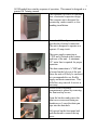
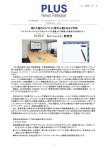
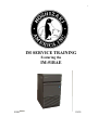
1
IM SERVICE TRAINING
Featuring the
IM-51BAE
80041
9/9/99
2
All IM models have similar sequence of operation. This manual is designed as a
generic IM Training manual.
The Hoshizaki IM series ice machine
uses a horizontal evaporator design.
This compact unit is designed for
counter-top, under-counter, or freestanding installations.
A standard 120 volt power cord
provides the electrical connection.
The unit is designed to operate on a
separate 15 amp circuit.
The water supply connection is
½”FIP and is located at the bottom
right rear of the unit. A minimum
3/8” water line is required for proper
operation.
The drain connection is ¾”MIP and
is located on the left rear of the unit.
Since the unit will likely be enclosed,
it is recommended to use flexible
supply and drain connections. This
will allow easy removal if service is
necessary.
Access to the evaporator
compartment is gained by removing
the front and top covers.
Open the bin door and remove the
front cover screws and drain pan
thumbscrews. Lower the drain pan
pipe into the drain hole.
Lift upward on the front panel and
push backward to remove the top
cover.
3
This horizontal evaporator and water
distribution system is unique to the
IM series.
The ABS water plate sprays water up
into the evaporator cells to form the
square IM cube.
The moveable water pan assembly
includes the water plate, reservoir
pan, and pump motor assembly.
Tension springs connect two cam
arms to the water plate assembly. An
actuator motor rotates the cam arms
to raise and lower the water pan
during the ice making cycle.
4
The front cam arm has a switch lever
that operates the actuator toggle
switch located above the pan
assembly.
The actuator toggle switch controls
the direction of rotation for the
actuator motor and energizes the
pump motor during the freeze cycle.
• When the switch is in the right
position, the actuator motor
rotates counter clock wise to
lower the water pan assembly.
• When the switch is in the left
position, the actuator motor turns
clock wise to raise the water pan
assembly.
The IM51 uses a mechanical
proximity switch bin control
assembly located in the bin area.
When ice fills the bin and pushes the
control arm over, the activator
magnet moves to the switch and
closes the contacts.
The IM bin control closes the
contacts to signal the control board
to shut down the unit. This is
different from the standard KM
control, which opens the contacts to
de-energize the unit.
5
The louver has a flip down cover to
access the control switch.
The switch has 3 positions.
ICE, OFF, & WASH.
The louver covers the compressor
compartment. Remove the louver
screws and lift the louver forward to
access the condenser coil fan
assembly and compressor.
For easy access during preventative
maintenance or service, the inlet
water valve is located in the front
right hand corner of the compressor
compartment.
6
The control box is accessed from the
rear of the unit. Remove the screws
holding the pipe cover and the
control box cover to reach the
control board and other components.
A solid state board controls the IM
operation. Several adjustments are
included on the board. These
adjustments are factory set for proper
operation.
Later, we will cover the adjustments
and discuss the proper settings.
CONTROL SWITCH TO ICE.
Now, lets take a look at the basic IM
sequence of operation. When the
control switch is placed in ICE, the
unit starts in the Initial Harvest cycle.
INITIAL HARVEST CYCLE.
FREEZE CYCLE.
NORMAL HARVEST CYCLE.
FREEZE, HARVEST,
FREEZE, HARVEST,
FREEZE, HARVEST,
“
“
When power is supplied, the
compressor, hot gas valve, and
actuator motor energize. The
compressor starts in harvest to
reduce the starting load and increase
compressor life. This will also clear
any ice from the evaporator plate
before the freeze cycle begins.
7
The actuator motor turns counter
clock wise to rotate the cam arms
and lower the water pan away from
the evaporator. When the water plate
is completely down the switch lever
moves the actuator toggle switch to
the left. The board energizes the
inlet water valve and condenser fan
motor and de-energizes the hot gas
valve.
Switching the actuator toggle switch
to the left position also reverses the
actuator motor. The motor now turns
clock wise to raise the water plate
upward.
When the plate reaches the
evaporator, the cam arm switch lever
moves the actuator toggle switch to
the right position. This stops the
actuator motor and sets up the circuit
to lower the plate in the next harvest
cycle. It also energizes the pump
motor and the board de-energizes the
inlet water valve. The Freeze Cycle
now begins.
8
The freeze cycle is controlled by a
thermistor, which is mounted at the
evaporator outlet. The pump is
spraying water up into the evaporator
cells to form the square IM cubes.
The evaporator temperature lowers
as the ice cubes form.
A thermistor temperature of –9.4°F
signals the control board to begin
harvest and energize the hot gas
valve and actuator motor circuit. The
actuator motor now turns counter
clock wise to lower the water pan.
The switch lever moves the actuator
toggle switch to the left. This sets the
actuator motor circuit to raise the
water plate at the end of harvest. The
board energizes the inlet water valve.
Unlike the initial harvest, the normal
harvest is controlled by the
thermistor. When the thermistor
reaches 59°F, the control board deenergizes the hot gas valve and
energizes the condenser fan motor.
The actuator motor energizes to raise
the plate. When the plate reaches the
evaporator, the actuator toggle
switch is moved back to the right.
The board de-energizes the inlet
water valve and the freeze cycle
begins again. The average harvest
cycle is about 3 minutes.
9
The unit will continue through the
freeze and harvest cycle until the bin
control shuts down the refrigeration
system.
When pushed over, the bin control
has a 10-second delay before shut
down occurs. An 85-second delay
occurs at startup when the bin
control is released.
Now let’s take a look at the control
board adjustments. Remember that
the adjustments are factory set to
provide proper operation in normal
operating conditions.
NO SEASONAL
ADJUSTMENTS!
The board adjustments are made
through variable resistors on the
board. The cube control is marked
VR5. This adjusts the thermistor
switching temperature of - 9.4°F and
the length of the freeze cycle. The
dimple size in the cube also changes.
Adjusting to a larger dimple will
result in a shorter freeze cycle and a
smaller cube. A smaller dimple
setting will result in a longer cycle
and a larger cube. The factory
setting is 5.
10
The maximum freeze timer is VR3.
This timer will automatically switch
the unit to the harvest cycle if the
freeze cycle last longer than the
setting time. The factory setting is
45 minutes.
The defrost control VR2 will adjust
the time period between ice-drop and
actuator motor restart during harvest.
The factory setting is 4. This setting
represents approximately 40 seconds.
VR2 would be adjusted longer if the
unit is operating in a cooler ambient
temperature.
The control board includes a pushbutton reset. Pressing this button
will initiate a harvest cycle anytime
the control switch is in ICE position.
11
A red Service Indicator LED is also
included on the control board. This
LED will either light continually or
flash to indicate a service fault. A
fault diagnosis chart in the service
manual will help the technician
determine the actual problem.
See chart next page.
Preventative maintenance for the IM
is simple. Follow these steps to allow
the unit to operate efficiently.
1. Clean the mesh air filter twice
monthly to ensure good airflow.
2. Clean the condenser once a year
using a brush or vacuum.
3. Check and clean the inlet water
valve screen as needed to assure
proper water flow.
4. Clean and sanitize the water
distribution system annually using
the recommended cleaner.
5. Wipe down the exterior using a
soft cloth and neutral cleaner.
Cleaning tips:
• A detailed cleaning label is
located under the top cover. More
detailed instructions are included
in the customers Instruction
Manual or in the product Service
Manual.
• Always follow the cleaning
instructions and use the
recommended ice machine
cleaner.
• Use the cleaning brush shipped
with the unit to clean tight places.
12
FAULT DIAGNOSIS
Check the status of the Service lamp on the Controller Board (LED-5) by removing the
Control Box Cover.
Lamp ON – Water Plate closed
This tends to indicate the Back-up Timer has stopped machine operation during the
freeze cycle. High ambient and water temperature are an obvious cause. But check
out each component that could result in an extended freezing time (See guide below).
Lamp ON – Water Plate open
The Timer has stopped the machine because if an excessive defrost time. See the
guide below to check out the probable cause.
Lamp flashing ON/OFF
If on the first cycle, check out the Cam operation and/or Toggle Switch. If the machine
has been in service for some time, the Controller Board may be at fault.
REMEMBER: Hoshizaki controllers are very reliable. They also control every component’s
Operation. So if a component malfunctions, the controller will respond.
Do not replace controllers in an attempt to shorten the diagnosis process and
not before carefully checking the actual fault and possible cause.
When the icemaker stops, the Controller Board Interlock indicator shows possible faults.
PATTERN
INTERLOCK
INDICATOR
WATER TANK
POSITION
POSSIBLE CAUSE
1.
1
Actuator
Toggle Switch
Lever bent
2
Can Arm (A) Broken
Only
First
Cycle
Flashing
REMEDY
Replace
Actuator
Toggle
Switch
Replace
Cam Arm
3
Defective
Actuator Motor
Replace
O
4
Defective
Controller Board
Replace
13
PATTERN
INTERLOCK
INDICATOR
WATER TANK
POSITION
POSSIBLE CAUSE
2
Clogged Air Filter
and/or Condenser
1
2
REMEDY
Clean or
Replace
Water leak from
Water Solenoid
Valve
Replace
Gas leak from Hot
Gas Solenoid
Valve
Replace
0V
Leak
Freeze Cycle
3
Hot Gas leak
4
Fan Motor
stopped
Replace
5
Gas leak
Check
for leak
Gas
Compressor
stopped
6
3
1
115v
Hot Gas Solenoid
Valve closed and
will not open
Gas leak
2
Gas
Harvest
Cycle
3
4
1
Lever
2
Compressor
stopped
Actuator
Toggle Switch
Lever bent
Can Arm (A) Broken
Replace
Comp. Start
Capacitor
Replace
Check
for leak
Replace
Comp. Start
Capacitor
Replace
Actuator
Toggle Swt.
Replace
Cam Arm
OR
3
Defective Actuator
Motor
Cam Pin
damaged
4
Actuator
motor
5
Pin
Defective Cube
Control Thermistor
Replace
Replace
Cam Pin
and Cam
Arm (A)
Replace
14
WIRING DIAGRAM
IM-51BAE
15
IM SERIES REVIEW QUIZ
Choose the best answer for each question below.
1. The IM control board is located in the rear or the unit.
True
False
2. The IM unit uses a thermostatic bin control.
True
False
3. The bin control switch must OPEN or Close to shut the unit down.
4. The IM series uses R-404A or R-134A refrigerant.
5. To raise the water pan assembly the actuator toggle switch must be in the
RIGHT or LEFT position.
6. With the actuator toggle switch in the left position, the actuator motor turns
CLOCKWISE or COUNTER CLOCKWISE.
7. Adjusting the cube control or dimple adjustment changes which temperature
setting? - 9.4ºF or 59ºF.
8. The maximum freeze timer on the control board is factory set at
60 MINUTES or 45 MINUTES.
9. The black push button reset is included on the control board for
HARVEST INITIATION or SAFETY RESET.
10. The control transformer used in the IM series units is a 12VOLT or 24
VOLT output.
NOTE: Quiz answers are at the bottom of next page.
16
NOTES:
Quiz answers:
1.True, 2. False, 3. Close, 4. R-134A , 5. Left , 6. CW , 7. – 9.4ºF,
8. 45 min., 9. Harvest initiation, 10. 24 volt