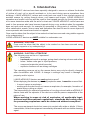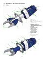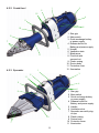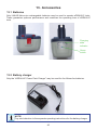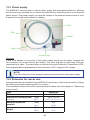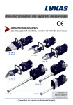
1
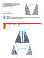
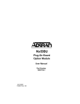
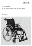
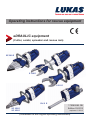
Operating instructions for rescue equipment
eDRAULIC equipment
(Cutter, combi, spreader and rescue ram)
SP 300 E
S 700 E
S 311 E
R 411 E
SC 350 E
SC 250 E
172080085 GB
Edition 03.2013
replaces 01.2012
(Translation of the original operating instructions)
Contents
Page
1. Danger classes
4
2. Product safety
5
3. Intended Use
8
4. Functional description
10
4.1 Description
10
4.2 Structure of the rescue equipment
11
4.3 Hydraulic circuit diagram
13
4.4 Controlling the operating movements
14
5. Operation
14
5.1 Battery or power supply for eDRAULIC device
14
5.2 Operating the star grip
15
6. Cutting, spreading, pulling, squeezing and squashing
6.1 Safety instructions
15
15
6.2 Cutting (cutter and combi tool)
16
6.3 Spreading (spreader and combi tool)
17
6.4 Pulling (spreader, combi tools)
18
6.5 Squeezing (spreader, combi tools)
19
6.6 Squashing (rescue ram)
20
7. Dismantling the equipment / deactivation following operation
21
8. Maintenance and service
21
8.1 Overview of eDRAULIC devices
22
8.2 Safety equipment
23
9. Repairs
23
9.1 General information
23
9.2 Preventive maintenance
24
9.3 Repairs
24
10. Troubleshooting
36
2
11. Technical data
38
11.1 eDRAULIC cutter
38
11.2 eDRAULIC combi tool
39
11.3 eDRAULIC spreader
40
11.4 eDRAULIC rescue ram
41
11.5 Noise emissions (based on the EN ISO 3744 standard)
41
11.6 Operating and storage temperature ranges
42
11.7 Oscillation / vibration
42
11.8 Tightening torques for pivot bolts (cutters and combi tools only)
42
12. EC Declarations of conformity
43
13. Accessories
45
13.1 Batteries
45
13.2 Battery charger
45
13.3 Power supply
46
13.4 Extension for rescue ram
46
13.5 Chain sets
47
14. Instructions regarding disposal
47
15. Notes
48
3
1. Danger classes
We distinguish between various categories of safety instructions. The table below provides
an overview of the symbols (pictograms) and signal words assigned to the specific danger
and also the possible consequences.
People
Damage /
injury to
Objects
Pictogram
Key word
Definition
Consequences
DANGER!
Immediate danger
Death or major
injury
WARNING!
Potentially
dangerous
situation
Potential death or
major injury
CAUTION!
Less dangerous
situation
Minor or slight
injury
Danger of
ATTENTION! damage to objects
/ environment
Damage to the
equipment,
damage to the
environment,
damage to
surrounding
materials
Advice for
application and
other important /
useful information
and advice
No injury /
damage to
persons /
environment /
equipment
-
NOTE
Wear a helmet with a face guard
Wear protective gloves
Wear safety shoes
Proper recycling
Observe principles of environmental protection
Read and observe operating instructions
4
2. Product safety
LUKAS products are developed and manufactured to guarantee the best performance and
quality when used properly.
Operator safety is the most important aspect of the product design. Moreover, the operating
instructions are intended to aid the safe use of LUKAS products.
The generally applicable legal and other binding regulations pertaining to the prevention of
accidents and protection of the environment apply and are to be complied with in addition to
the operating instructions.
The device may only be operated by persons with appropriate training in the safety aspects
of such equipment – otherwise, there is a danger of injury occurring.
We would like to point out to all users that they should read the operating instructions
carefully before using the equipment and fully comply with the instructions therein.
We further recommend you have a qualified trainer show you how to use the product.
WARNING / CAUTION!
The operating instructions for accessories must also be taken into account!
Even if you have already received instruction, you should read the following safety instructions
again.
WARNING / CAUTION!
Please ensure that the accessories you use are appropriate for the maximum
operating pressure and the performance of the rescue device!
Please ensure that no body
parts or clothing are caught
between the visible moving
parts (e.g. blade arms).
Working under suspended
loads is not permitted if
these are supported only
using hydraulic or electrohydraulic devices. If this
work is unavoidable, suitable
mechanical supports are also
required.
Wear protective clothing,
a safety helmet with visor,
protective footwear and
gloves.
Inspect the device before and
after use for visible defects or
damage.
The department responsible
must be informed immediately
of any apparent changes
(including the operating
behaviour). If necessary,
the equipment is to be
deactivated immediately and
secured!
All screwed connections must
be checked for leaks and
visible damage, which must
be repaired immediately!
Squirting hydraulic fluid can
result in injuries and fires.
5
In the event of malfunctions,
shut down the device
immediately and make it safe.
Repair the fault immediately.
Observe all safety and danger
information on the device and
in the operating instructions.
Do not carry out any changes
(additions or conversions)
to the equipment without
obtaining the approval of
LUKAS beforehand.
All safety and danger
information on the device
must always be complete and
in a legible condition.
Repairs to the device may
only be carried out by trained
service technicians with
specific knowledge of the
device.
Use only original LUKAS
accessories and spare parts
when carrying out repairs.
Any mode of operation which
compromises the safety and/
or stability of the device is
forbidden!
Safety equipment must never
be disabled!
Make sure before switching
on/starting up the device and
during its operation, that this
will put no one in danger.
Observe all intervals
for recurring tests and/
or inspections that are
prescribed or stated in the
operating instructions.
When working in the vicinity
of live components and
cables, appropriate measures
must be taken to avoid a
transfer of current or highvoltage arcing to the device.
Please note that material
could fall down or suddenly
break free during spreading,
cutting, squeezing and
squashing operations as a
result of shearing, tearing
or breaking; appropriate
countermeasures must
Please ensure that the
battery contacts are not shortcircuited.
Please ensure that you do not
become entangled in cables
and trip when working with or
transporting the device.
Only touch any broken-off
parts or the cut-off parts
wearing protective gloves,
since the torn / cut edges can
be very sharp.
The build-up of static charge
and therefore possible
sparking must be avoided
when handling the device.
6
Protect the eDRAULIC
devices against humidity and
moisture
The eDRAULIC devices are
not suitable for underwater
use.
The equipment is filled
with hydraulic fluid. These
hydraulic fluids can be
dangerous to health if
swallowed or their vapours
inhaled. Direct contact with
the skin is to be avoided for
the same reason. Please also
note that hydraulic liquids can
also have a negative effect on
biological systems.
When working with or storing
the equipment, ensure
that the function and the
safety of the equipment
are not impaired by the
effects of extreme external
temperatures or that the
equipment is damaged in
any way. Please note that the
equipment can also heat up
over a long period of use.
Ensure adequate lighting
when you are working.
Before transporting the
equipment, always ensure
that the accessories are
positioned such that they
cannot cause an accident.
Always keep these operating
instructions within reach
where the equipment is used.
Ensure the proper disposal of
all removed parts, left-over oil
and hydraulic fluid as well as
packaging materials!
The generally applicable, legal and other binding national and international regulations
pertaining to the prevention of accidents and protection of the environment apply and are to
be implemented in addition to the operating instructions.
WAR N IN G / C A U TION / AT T E NT I O N!
The device is intended exclusively for the purpose stated in the operating instructions
(see chapter "Intended Use"). Any other use is not in accordance with its designated use.
The manufacturer/supplier cannot be held liable for any damage resulting from such use.
The risk of such misuse lies entirely with the user.
Intended Use includes observance of the operating instructions and compliance with the
inspection and maintenance conditions.
Never work when you are overtired or intoxicated!
7
3. Intended Use
LUKAS eDRAULIC devices have been specially designed to rescue or retrieve the bodies
of victims of road, rail or aircraft accidents or to be used during rescue operations from
buildings. LUKAS eDRAULIC cutters and combi tools are used to free injured persons at
accident scenes by cutting through doors, roof beams and hinges. LUKAS eDRAULIC
spreaders and combi tools can also be used to free trapped persons by forcing open doors
or to move obstacles aside with the aid of a chain set. LUKAS eDRAULIC rescue rams are
used to free persons who have become trapped during a car accident when the spreader
does not open wide enough, for example by spreading or lifting parts of vehicles. During
other catastrophic events, rescue rams and spreaders can also be used to move objects to
rescue persons who have been buried or trapped.
Care must be taken that the object to be worked on has been secured using stable supports
or by underpinning it.
LUKAS eDRAULIC devices are NOT suitable for underwater use.
WARNING / CAUTION!
Care must be taken that the object to be worked on has been secured using
stable supports or by underpinning it.
WARNING / CAUTION / ATTENTION!
The following may not be cut / squeezed:
- live cables
- hardened parts such as springs, spring steels, steering columns and rollers
- tubes / hoses under gas or liquid pressure,
- compound materials (steel/concrete)
- explosive bodies such as airbag cartridges
The operating pressure set on the rescue device may only be directly changed
after consultation with LUKAS. A change in settings may result in damage to
property and/or injuries.
LUKAS eDRAULIC devices are not explosion-proof!
When deploying the devices in potentially explosive areas, it must be ensured that:
- it cannot cause an explosion.
- working with the device will not cause an explosion; for example, formation of
sparks when cutting an object.
The responsibility for explosion prevention or for ruling out work with an eDRAULIC
device rests with the operator of the device or with the person responsible at the
place of use.
When working in areas at risk of explosion, all applicable legal,
national and international regulations, standards and safety rules
for preventing explosions must be observed without exception!
The rescue equipment should not come into contact with acids or alkalis. If this is
unavoidable, clean the equipment immediately afterwards with a suitable cleaning
agent.
8
You can order spare parts and accessories for the rescue tools from your authorised LUKAS
dealer!
Applications:
9
4. Functional description
4.1 Description
The cutters and combi tools have been designed in such a way that a hydraulically operated
piston activates mechanical joints symmetrically to open or close a set of two opposite blade
arms, thus enabling objects to be cut.
The spreaders operate according to a similar principle. They, too, have been designed in
such a way that a hydraulically operated piston activates mechanical joints symmetrically
to open or close a set of two opposite spreader arms. This movement can then be used to
spread open, squeeze or pull open objects.
The rescue rams are double-acting hydraulic cylinders. Extension and retraction takes place
hydraulically.
On all devices, the movement is activated by means of a valve in the form of a star grip.
All devices guarantee the dead man's switch and the full load-supporting function when the
star grip is released.
LUKAS eDRAULIC devices do not need to be connected to an external hydraulic source
(e.g. a motor pump). The hydraulic pressure required is generated within the body of the
device.
Either a battery or an external power supply must be connected as an energy source.
You can choose which energy source you wish to use. Both the battery and the power unit
can be plugged into the opening provided in the body of the tool. Both will lock in place automatically.
When using batteries as an energy source, you have almost unlimited freedom of movement
when working, i.e. there are no cables or hoses to hinder you. You can extend the operating
time of your eDRAULIC device by using several batteries. The batteries can be recharged
after use, using a suitable external charger
If you use an external power supply, the operating time is essentially unlimited; this is only
restricted by the external power source and the thermal switch in the power unit.
To allow you to select the best possible energy supply for your eDRAULIC device, neither the
battery nor the power supply form part of the delivery scope. You will find suitable batteries
and power supplies in the LUKAS accessories list.
eDRAULIC devices are equipped with lighting as standard so that work can be carried out in
conditions where visibility is poor.
The light-emitting diodes attached on the operating side light up the work area. The main
switch has also been provided with a light, so that you can see at a glance whether the device is switched on. When exchanging the battery or power supply, the connection slot will
be lit up for approximately 30 seconds.
10
4.2 Structure of the rescue equipment
4.2.1 Cutter
1
3
2
4
12
10
11
6
8
9
5
7
11
1 Star grip
2 Main switch
3 Quick exchange battery or
power supply
4 Release button for
Battery and power supply
5 Handle
6 Ventilation slots
7 Blade arms
8 Pivot bolt with
secured nut
9 Plastic casing
10 Device body
11 Protective cover
12 Illumination
1
2
3
12
5
4
11
8
6
7
10
11
9
1
4.2.2 Combi tool
3
2
12
4
5
6
10
1 Star grip
2 Main switch
3 Quick exchange battery
or power supply
4 Release button for
Battery and power supply
5 Handle
6 Ventilation slots
7 Blade arms
8 Pivot bolt with
secured nut
9 Plastic casing
10 Device body
11 Protective cover
12 Illumination
8
7
9
11
1
4.2.3 Spreader
3
2
11
5
4
9
8
10
7
12
6
1 Star grip
2 Main switch
3 Quick exchange battery
or power supply
4 Release button for
Battery and power supply
5 Handle
6 Ventilation slots
7 Spreader arms with plugon tips
8 Plastic casing
9 Device body
10 Protective cover
11 Illumination
4.2.4 Rescue ram
11
3
1
10
2
8
11
4
9
5
7
6
1 Star grip
2 Main switch
3 Quick exchange battery
or power supply
4 Release button for
Battery and power supply
5 Ventilation slots
6 Cylinder piston
7 Plastic casing
8 Device body
9 Top claw
10 Bottom claw
11 Illumination
NOTE:
When working with the eDRAULIC rescue ram, it should be applied to the object
to be processed in such a way that the battery or power supply can be replaced
at any time.
4.3 Hydraulic circuit diagram
To enable comprehension of the function, a simplified hydraulic cylinder of the rescue
equipment (A) + hand valve (B) are depicted here.
cut / close / pulling /
squeezing
or extend piston
A
spreading /
opening
or retract piston
B
13
4.4 Controlling the operating movements
The piston movement is controlled by the star grip on the attached valve (see illustration
below).
Star grip
5. Operation
5.1 Battery or power supply for eDRAULIC device
5.1.1 Initial start-up
Before initial operation, the battery (where used) of the rescue device must be fully loaded,
using the external charger.
Procedure:
1. Unplug the power supply (where used) from the mains.
2. Fully press down the two unlocking buttons and carefully pull the battery or power
supply out of the device.
Do not use force!
Connection slot
3. The battery can now be recharged in the charger (please take note of the separate
operating instructions for the charger and the batteries to be used); alternatively,
the power supply can be replaced.
4. Insert the recharged or new battery into the eDRAULIC device until it reaches the stop.
The battery or power supply will be automatically locked when correctly operated.
14
5.2 Operating the star grip
(also see chapter on "Controlling the operating movements")
Open the device or extend the piston (
/
):
Turn the star grip in the direction of the corresponding symbol
(open / extend)and hold it in this position.
Close the device or retract the piston (
/
):
Turn the star grip in the direction of the corresponding symbol
(close / retract)and hold it in this position.
"Dead-man’s" function:
Once released, the star grip automatically returns to the central
position while fully guaranteeing the load will remain supported.
6. Cutting, spreading, pulling, squeezing and squashing
6.1 Safety instructions
Before rescue work can commence, the position of the accident object must be stabilised.
You must ensure that it is adequately underpinned and/or supported.
World-wide, safety guidelines pertaining to the specific country must be observed and
complied with. In the Federal Republic of Germany, regular safety inspections according
to the legal accident insurance regulations (GUV - Gesetzliche Unfallversicherung) are
mandatory.
WARNING / CAUTION / ATTENTION!
LUKAS eDRAULIC devices are not explosion-proof!
When deploying the devices in potentially explosive areas, it must be ensured
that:
- it cannot cause an explosion.
- working with the device will not cause an explosion; for example, formation of
sparks when cutting an object.
The responsibility for explosion prevention or for ruling out work with an eDRAULIC
device rests with the operator of the device or with the person responsible at the
place of use.
When working in areas at risk of explosion, all applicable legal,
national and international regulations, standards and safety rules
for preventing explosions must be observed without exception!
15
Wear the following when working with the rescue tool:
- protective clothing,
- safety helmet with visor or protective goggles,
- protective gloves
- and, if necessary, ear protection
Before operating the rescue tool, you should ensure that its movements or flying fragments
will not put participants or bystanders at risk! Further avoid unnecessary damage to property
belonging to others, objects not involved by the rescue equipment / flying fragments.
It is strictly prohibited to reach into the path of the rescue
device (e.g. between the blades or spreader arms or
between the rescue ram and the material to be processed)!
WARNING / CAUTION!
The particular effect of the force of the rescue equipment during operation could
cause pieces of the vehicle to break off or fly off, posing a danger to persons.
Those not involved in the rescue operation should therefore keep at a distance
appropriate to the situation. Any trapped or enclosed persons must be protected.
6.2 Cutting (cutter and combi tool)
The blades should be positioned at a 90° angle to the object to be cut, if possible.
15° 15°
12
90°
9
3
RIGHT
16
WRONG
Higher cutting capacities can be achieved by cutting as close as possible to the blade’s pivot point.
WRONG
RIGHT
During cutting, the gap between the blade tips (in the transverse direction) must not be
exceeded, otherwise the blade is in danger of breaking:
eDraulic tool
S 311 E
S 700 E
SC 250 E
SC 350 E
max. gap on the blade tips
[mm] / [in.]
3 / 0.12
3 / 0.12
3 / 0.12
3 / 0.12
ATTENTION!
Avoid cutting through the hardest parts of the vehicle body (e.g. lateral collision
protection), as this may result in damage to the cutters or to more wear and tear!
6.3 Spreading (spreader and combi tool)
Use the front area of the tips for increasing the gap only. To increase grip and to avoid having
the tips slip or break out of the part to be processed, the grip should be reapplied at an early
stage. In any case, the highest force is developed in the rear area of the plug-on tip or in the
rear spreading area of the combi blades.
WARNING / CAUTION / ATTENTION!
The light metal alloy spreader arms must not be damaged.
Enlarging a gap
Spreading
approx. 25 mm
approx. 1 in.
17
Working surface is too small,
tips slip off.
Only for increasing the size
of a gap (not suitable for
spreading)
Tips get a safe grip.
Work with the tips only.
Do not damage the
spreader arms!
6.4 Pulling (spreader, combi tools)
WARNING / CAUTION / ATTENTION!
The light metal alloy arms must not be damaged.
- LUKAS chain sets must be used for pulling.
- When using the traction chain, the pins and hooks must be in the correct position
to ensure that the chain cannot slip.
- Only chain sets in perfect condition may be used.
- The traction chains must be checked by an expert at least once a year.
- Also consult the separate operating instructions for the corresponding chain set!
Attachment hole
for chain sets
18
The connection pieces for the LUKAS
chain sets are attached to the boreholes
A on the blades using load bolts.
(see figure on the right).
A
Chain sets:
for SC250E: KSV 8/50
for SC350E: KSV 8/50
for SP300E: KSV 11
NOTE:
Take note also of all the instructions and regulations in the separately supplied
operating instructions for the chain sets.
6.5 Squeezing (spreader, combi tools)
WARNING / CAUTION / ATTENTION!
The light metal alloy arms must not be damaged.
Squeezing area
Squeezing may only take place near the tips (see figure below).
Squeezing area
19
6.6 Squashing (rescue ram)
Before you can carry out any work with the rescue ram, you must ensure adequate support.
This also includes any necessary substructure. As part of their design, the rescue rams are
fitted with claws at the cylinder and piston ends to ensure it is as safe as possible to use.
Where this support is not adequate, e.g. when pushing away the front part of the vehicle or
when pushing a vehicle upwards, additional supports and ram attachments may be required,
and it may need to be secured, using straps for example. You will find suitable support
bearings and cylinder attachments in the LUKAS accessories list.
WARNING / CAUTION / ATTENTION!
Never use a rescue ram without a claw or the required accessories! The cylinder
could slip during the operation, resulting in injury to the user. In addition, the
piston rod or the claw support could be damaged.
WARNING / CAUTION / ATTENTION!
When applying the rescue ram (without the LUKAS support), care must be taken
to ensure that all four tips of both claws, i.e. on the piston and the cylinder side,
are in good contact with the object.
When applying the rescue ram (to a LUKAS support), care must be taken to
ensure that the surface between the four tips of the claw is in contact with the
round bearing rods.
This prevents force from acting on only one end of the cylinder. Objects lifted up
must be subsequently secured with firm supports or substructures!
An extension is also available for the eDRAULIC rescue ram.
B
A
Procedure for installing the extension:
1. First pull the claw "A" off the cylinder base.
Check whether the O-ring "B" is still attached
to the cylinder base and is in good condition.
Where necessary, replace the O-ring.
2. Check the good fit of the O-ring "B", grease the contact surfaces using LUKAS special
grease and insert the extension "C" onto the cylinder base until it reaches the stop.
B
C
3. When the extension is no longer required after the operation, remove it by following the
instructions in the reverse order and store it in a suitable place.
20
7. Dismantling the equipment / deactivation
following operation
Once work has been completed, the arms should be closed until the tips are only a few
millimetres apart or the cylinder piston should be almost fully retracted. This relieves the
hydraulic and mechanical strain on the device as a whole.
NOTE:
Never store the eDRAULIC devices with fully closed arms or a fully retracted
piston! By fully closing the arms or retracting the cylinder piston, hydraulic and
mechanical tension may develop in the device.
Clean the rescue device after each operation and grease both the metallic and the
mechanically movable parts. The locking mechanism for the spreader plug-in tips should
also be oiled now and again.
Greasing provides protection against excessive wear and tear or corrosion.
Avoid storing the rescue equipment in a damp environment.
8. Maintenance and service
The devices are subject to very high mechanical stresses. A visual inspection must therefore
be carried out after every use and at least one visual inspection must be carried out every
six months. These inspections enable the early detection of wear and tear, which means that
punctual replacement of this wearing parts prevents breakages from occurring. Regularly
check the torque of the pivot bolt on the cutters and combi tools. (You will find the tightening
torques for the pivot bolt in the chapter "Technical data")
An annual inspection of the tool is due once per year. This inspection must be performed by
a person with the necessary expertise. This means that the person must possess adequate
specialist knowledge and experience in the fields of electrical engineering and hydraulics, so
that they can objectively assess the condition of the tool.
Every three years a crack test of the blades is also essential. A special crack testing kit is
available for this.
A functional test must also be performed every three years or if there is any doubt regarding
the safety or reliability of the equipment (please also observe the applicable national and
international regulations pertaining to service intervals of rescue tools). In the Federal
Republic of Germany, regular safety inspections according to the legal accident insurance
regulations (GUV - Gesetzliche Unfallversicherung) are mandatory.
ATTENTION!
Clean off any dirt before checking the device!
WARNING / CAUTION / ATTENTION!
In order to carry out maintenance and repair work, tools appropriate for the job
and personal protection equipment must be used.
The maintenance and repair staff must have adequate technical and specialised
knowledge. LUKAS offers appropriate training courses for this.
21
8.1 Overview of eDRAULIC devices
Inspections to be carried out:
Visual inspection
Cutter and combi tool
• Opening width of the blade arms on the tips (see chapter "Technical data"),
• General tightness (leaks),
• Ease of movement of star handle,
• Existence and stability of handle,
• Labels completely existent and legibly,
• Covers in perfect condition,
• Check the tightening torque of the pivot bolt (tightening torque MA see "Technical data").
• Blade arms free of cracks and cutting surfaces without nicks or deformations,
• Cutting surfaces go on top of each other without making contact,
• The sliding plates, bolts and retaining rings of the blade arms are in place and in good
condition,
• Illumination of main switch, work area and connection slot fully functional.
Spreader
• Opening width of arms at the tips (see chapter on "Technical Data"),
• General tightness (leaks),
• Ease of movement of star handle,
• Existence and stability of handle,
• Labels completely existent and legibly,
• Covers in perfect condition,
• Spreader arms not cracked,
• Bolts and retaining rings of spreader arms in place and in good condition,
• The corrugations on the tips should be clean and square, without cracks
• The tips must be in place and locked
• Illumination of main switch, work area and connection slot fully functional.
Rescue ram
• Piston can be extended to its full length (see chapter on "Technical Data"),
• Cylinder and piston rod undamaged and not deformed,
• Claws correctly and securely fitted,
• Claws can be turned and are undamaged (no break-outs),
• General tightness (leaks),
• Ease of movement of star handle,
• Labels completely existent and legibly,
• Illumination of main switch, work area and connection slot fully functional.
22
Battery and power supply
• Casing undamaged,
• Electrical contact surfaces clean and undamaged
• Cable undamaged
• Battery(-ies) fully charged (when used)
• Charging state display of lithium/ion battery(-ies) fully functional
Functional check
• Easy opening and closing or extension/retraction of star grip controls,
• no suspicious noises.
• no further movement of cutter and spreader arms or cylinder piston when interrupting the
valve function during the process (dead man's switch),
8.2 Safety equipment
• Check of the protective equipment on / around the rescue equipment, especially the hand
guard for the moveable parts (this must be free of cracks!).
9. Repairs
9.1 General information
Servicing may only be carried out by the manufacturer or personnel trained by the
manufacturer and by authorised LUKAS dealers.
Only LUKAS spare parts may be used to replace all components (see spare parts list) since
special tools and compliance with assembly instructions, safety aspects and inspections
must be taken into account (see also chapter "Maintenance and Servicing").
During assembly, make especially sure that all components are clean, since dirt can
damage the rescue tool!
WARNING / CAUTION / ATTENTION!
Protective clothes must be worn when repairs are being carried out, since the
devices may also be pressurised when not in operation.
NOTE:
Always register your tool on the LUKAS Hydraulik GmbH internet site. Only then
are you entitled to the extended guarantee.
ATTENTION!
Because LUKAS rescue tools are designed to deliver outstanding performance,
components must only be replaced with those that are listed in the spare parts
lists for the corresponding device.
Other components in the device may only be replaced if:
- you have participated in an appropriate LUKAS service training course.
- you have the express permission of LUKAS Customer Service (valid LUKAS
certificate necessary!)
23
ATTENTION!
When cleaning the equipment, take care not to use any cleaning agent with a pH
value outside the range 5 - 8!
9.2 Preventive maintenance
9.2.1 Care instructions
From time to time, the outside of the device should be cleaned with a damp cloth (not the
electrical contacts in the connection slot, the battery or on the power supply) and oil
should be applied to the metallic surfaces (not the electrical contacts in the connection
slot, on the battery or on the power supply) to prevent corrosion.
(In case of doubt, contact your authorised LUKAS dealer or LUKAS directly!)
9.2.2 Functional and stress test
If there is any doubt regarding the safety or reliability of the equipment, a function and stress
test must also be performed.
LUKAS offers appropriate testing equipment for this.
9.3 Repairs
9.3.1 Blades, protective cover and handle replacement for the S700E cutter
Components to be
replaced
Required work
steps
Protective cover
1., 2. and 7.
Pivot bolt
1. - 4. and 7.
Handle
1. - 5. and 7.
Blade
1. - 6. and 7.
24
Work steps:
1. First of all, carefully clean the rescue equipment.
2. Remove the fixing screws "A" and
remove the protective cover "B" and the
cover caps "C".
C
B
D
A
B
C
3.
Move the blade arms on the unit
until the pin "E" and the retaining
rings "F" can be accessed through
the hole "D".
Now switch off the device and
remove the battery or unplug the
power supply from the device.
F
E
25
H
G
4. First remove the grub screw "G", then
the central bolt nut "H" and then pull out
the central pin "J".
L
J
5.
Release the fixing screws "K" and
remove them. The handle "L" can
now be pulled out forwards over the
blades.
N
O
K
M
6. Remove the retaining rings "M" and push
the pin "N" out. You can then pull out the
blades "O" and the slide plates "P"
P
M
N
O
7.
The work steps must be carried out in reverse order to fit the new parts.
ATTENTION!
Don’t forget to apply LUKAS special grease to all sliding surfaces.
NOTE:
The torque required can be taken from the spare parts list of your particular unit.
26
9.3.2 Changing the blades, protective cover and handle on the S311E cutter
and on the SC350E and SC250E combi tools
NOTE:
The illustrations show the equipment with the blade arms of the cutter. Assembly
and disassembly are identical for the combi tool!
Components to be
replaced
Required work
steps
Protective cover
1. - 9. and 10.
Pivot bolt
1., 5. and 10.
Handle
1. - 3. and 10.
Blade
1. - 7. and 10.
Work steps:
1. First of all, carefully clean the rescue equipment.
2. Next, close the blade arms so that the tips are almost touching.
NOTE:
The blade bolts are only accessible when the blade arms are almost touching
Further procedure:
3. Remove screws "A" from handle "B".
The handle can then be removed.
B
A
F
4.
Push the hand guard E in the
depicted direction until the safety
bolts F are easily accessible.
E
F
27
D
5. Remove self-locking nut D and push the
pivot bolt G out.
H
J
G
6.
Remove the retaining rings H and
push out bolt J.
L
H
J
7. Now, you can remove blade K and
sliding plates L.
M
K
8.
Fold in the lever elements M.
M
9. Finally, pull the hand guard "E" off the
device as shown.
E
28
10. The work steps must be carried out in reverse order to fit the new parts.
ATTENTION!
Don’t forget to apply LUKAS special grease to all sliding surfaces.
ATTENTION!
The nut of the pivot bolt and the pivot bolt itself are matched by a special procedure.
Therefore they must only be changed as a set by using a new set! Owing to the
special method used, any loosening of the nut while working will be minimised thus
preventing the blade from breaking.
The nuts can be unscrewed and tightened up to 10 times without affecting the
service life!
NOTE:
The torque required can be taken from the spare parts list of your particular unit.
9.3.3 Sharpening the blades
Only remove and smoothen any burrs!
Chips or deep grooves cannot be ground away. The blades must be replaced in these cases.
ATTENTION!
Only grind in the grinding area (see illustration)!
The sliding faces, in particular, must not be reground!
Grinding area
Pivot point
Blade arm
Direction of movement
Blade arm
Slide surface
plane
Tools required:
1. Use jaw protection on clamping device (e.g. vice) in order not to
damage the blades
2. Grinder (e.g. angle grinder or belt grinder) with abrasive having
a grain size of 80.
29
Procedure:
1. Clamp the blade securely into the clamping device so that it cannot move, but with the
grinding area exposed.
2. Carefully grind the burr away evenly until you reach the sliding surface level.
(see illustration)
Slide surface plane
In addition, when grinding, you must make sure that the inclination of the cutting surface
in the direction of the blade arm movement is not changed. Check the incline and
smoothness of the ground surface, using a suitable measuring tool.
ATTENTION!
If you have not maintained the smoothness or incline, the proper operation of the
blade is no longer guaranteed and the blades must be replaced.
9.3.4 Spreader arm, spreader tips, protective cover and handle exchange for
the spreader
Components to be
replaced
Required work
steps
Handle
1., 2. and 8.
Plug-on tips
1., 5. and 8.
Protective cover
1. - 4. and 8.
Lever links
1. - 4., 6. and 8.
Spreader arms
1. - 6. and 8.
30
Work steps:
1. First of all, carefully clean the rescue equipment. Now switch off the device and remove
the battery or unplug the power supply from the device.
A
2. Remove the fixing screws "A" and
remove the handle "B".
B
3.
C
C
Remove the screws "C" and "D".
D
C
C
31
E
4. Remove the two two-piece locking
elements "E" on the protective cover "F"
and remove the two-piece protective
cover by pulling it sideways.
F
F
5.
H
In order to remove the plug-on tips
"G", you must simultaneously press
the buttons "J" on each side of a
spreader arm "H" fully together and
then pull the plug-on tip forwards off
the spreader arm.
J
H
J
G
G
32
6. You need to remove the retaining rings "K" and the lever links "L" to replace the
spreader arms "H".
K
L
K
L
H
L
K
L
K
K
7. Also remove the retaining rings "M" and remove the pins "N". You can then remove the
spreader arms "H".
H
M
N
H
M
33
8.
The work steps must be carried out in reverse order to fit the new parts.
ATTENTION!
Don’t forget to apply LUKAS special grease to all sliding surfaces.
NOTE:
The torque required can be taken from the spare parts list of your particular unit.
9.3.5 Rescue ram
Work steps for exchanging the cylinder piston claw:
1. First of all, carefully clean the rescue equipment. Now switch off the device and remove
the battery or unplug the power supply from the device.
A
B
2. Pull the claw "A" off the cylinder piston
and remove the O-ring "B". Where the
O-ring is damaged, it must be replaced.
3. Insert the O-ring "B" into the groove of the new claw "A" provided and check it for a firm
fit. Grease the contact surfaces with LUKAS special grease and thenslide the new claw
onto the cylinder piston up to the limit stop.
Work steps for exchanging the cylinder base claw:
1. First of all, carefully clean the rescue equipment. Now switch off the device and remove
the battery or unplug the power supply from the device.
D
C
2. Pull the claw "C" off the cylinder base
and check whether the O-ring "D" in the
cylinder base has been damaged; if yes,
replace it.
3. Check the firm fit of the O-ring "D", grease the contact surfaces with LUKAS special
grease and then slide the new claw "C" onto the cylinder base up to the stop.
34
9.3.6 Labels
All damaged and/or illegible labels (safety instructions, type plate, etc.) must be renewed.
Procedure:
1. Remove damaged and/or illegible labels.
2. Clean surfaces with industrial alcohol.
3. Affix new labels.
Take care to affix the labels in the correct positions. If you are no longer sure about this, then
please contact your authorised LUKAS dealer or LUKAS itself.
35
10. Troubleshooting
Trouble
Blades, spreader
arms or cylinder
pistons move slowly
or jerkily when
operated
Control
Battery fully
charged?
Cause
Battery flat
Solution
Charge battery
Battery defective
Replace battery
Air in the hydraulic
system
Repair by authorised
dealer, staff specially
trained by LUKAS or
directly by LUKAS
Reinsert power
supply into the
connection slot.
Power supply cable Power supply
connected?
not properly
connected to the
eDRAULIC device
(not automatically
locked).
Power supply
cable not properly
connected to the
external power
supply.
Power supply or
power supply cable
defective.
Blades, spreader
arms or cylinder
pistons do not move
when operated.
Battery fully
charged?
Replace power
supply or power
supply cable.
External power
source defective.
Use other external
power source
Battery flat
Charge battery
Battery defective
Replace battery
Power supply cable Power supply cable Replace power
connected?
defective
supply cable
Device defective
Device doesn’t
perform at its given
power
Reconnect external
power supply.
Device defective
36
Repair by authorised
dealer, staff specially
trained by LUKAS or
directly by LUKAS
Repair by authorised
dealer, staff specially
trained by LUKAS or
directly by LUKAS
Trouble
Following release,
the star grip doesn’t
return to the central
position
Control
Casing damaged or
star grip operation
does not work
smoothly?
Cause
Damage to the
torsion spring for
reset
Soiled valve or star
grip
Solution
Repair by authorised
dealer, staff specially
trained by LUKAS or
directly by LUKAS
Defective valve
Other mechanical
damage (e. g. star
grip)
Hydraulic fluid leaks
on the piston rod
Defective rod seal
Damage to the
piston
Repair by authorised
dealer, staff specially
trained by LUKAS or
directly by LUKAS
The useful operating
time between the
individual charging
cycles is less than
5 minutes, despite
charging the batteries
according to the
instructions.
Battery defective
Replace battery
If you cannot rectify the malfunctions, inform an authorised LUKAS dealer or the LUKAS
customer service department immediately!
The address of the LUKAS Customer Service Department is:
LUKAS Hydraulik GmbH
Weinstraße 39
91058 Erlangen
Germany
Tel.: (+49) 09131 / 698 - 348
Fax.: (+49) 09131 / 698 - 353
37
11. Technical data
Since all values are subject to tolerances, minor differences may occur between the data on
your equipment and the data in the following tables.
The values may also differ because of reading inaccuracies and/or tolerances in the
measuring equipment used.
NOTE:
The following tables contain only the technical data necessary for operation and
storage.
Further information about your device is available directly from LUKAS.
11.1 eDRAULIC cutter
Type
S 311 E
Ref.no.
90-20-20 (172090000) 90-20-70 (172080000)
Dimensions (without battery) [mm]
lxwxh
[in.]
Max. cutting opening
S 700 E
860 x 225 x 290
925 x 300 x 290
33.86 x 8.86 x 11.42
36.42 x 11.81 x 11.42
[mm]
150
185
[in.]
5.91
7.28
[kg]
19,4
24,5
[lbs.]
42.8
54.0
Weight (excl. battery)
Nominal electrical voltage
(with power supply)
[V]
24
Nominal electrical voltage
(with lithium/ion battery)
[V]
25,2
Protection category
Classification (NFPA 1936)
IP44
A7/B8/C6/D7/E7
38
A8/B9/C8/D9/E9
11.2 eDRAULIC combi tool
Type
SC 250 E
SC 350 E
90-30-10
(173000000,
173115000)
90-30-20 (173010000)
[mm]
870 x 215 x 295
908 x 225 x 290
[in.]
34.3 x 8.5 x 11.6
37.8 x 8.9 x 11.4
233
265
Ref.no.
Dimensions (excl. battery)
lxwxh
Max. cutting opening
[mm]
[in.]
9.2
10.43
Max. cutting force
(rearmost cutting point)
[kN]
280
360
[lbf.]
62,944
80,928
Maximum spreading force
(at a distance of 25mm / 0.98in.
from the tips)
[kN]
33
40
[lbf.]
7,418
8,991
LSF spreading force
(according to NFPA)
[kN]
23
24
[lbf.]
5,170
5,396
HSF spreading force
(according to NFPA)
[kN]
29
37
[lbf.]
6,519
8,318
[kN]
184
350
Max possible spreading force
[lbf.]
41363
78,687
[mm]
320
360
[in.]
12.6
14.17
[kN]
Maximum pulling force
(on attachment hole for chain set) [lbf.]
34
41
7,643
9,218
[mm]
Pulling distance
(on attachment hole for chain set) [in.]
330
371
13.0
14.6
Maximum spreading distance
HPF pulling force
(according to NFPA)
[kN]
37
49
[lbf.]
8,318
11,014
LPF pulling force
(according to NFPA)
[kN]
27
30
[lbf.]
6,070
6,744
[kg]
16,9
19,8
[lbs.]
37.3
43.7
Weight (excl. battery)
Nominal electrical voltage
(with power supply)
[V]
24
24
Nominal electrical voltage
(with lithium/ion battery)
[V]
25,2
25,2
IP44
IP44
A6/B6/C6/D7/E7
A6/B7/C7/D7/E7
Protection category
Classification (NFPA 1936)
39
11.3 eDRAULIC spreader
Type
SP 300 E
Ref.no.
90-10-15 (171050000)
[mm]
Dimensions (excl. battery)
lxwxh
Maximum spreading force
(at a distance of 25mm / 0.98in.
from the tips)
Max. possible spreading force
895 x 355 x 290
[in.]
35.2 x 14.0 x 11.4
[kN]
44
[lbf.]
9900
[kN]
125
[lbf.]
28100
LSF spreading force
(according to NFPA)
[kN]
33
[lbf.]
7400
HSF spreading force
(according to NFPA)
[kN]
40
[lbf.]
9000
[mm]
605
[in.]
23.8
Maximum pulling force
(on attachment hole for chain set)
[kN]
31
[lbf.]
7000
Pulling distance
(on attachment hole for chain set)
[mm]
475
[in.]
18.7
HPF pulling force
(according to NFPA)
[kN]
24
[lbf.]
5200
[kN]
20
Maximum spreading distance
LPF pulling force
(according to NFPA)
Weight (excl. battery)
[lbf.]
4300
[kg]
21
[lbs.]
46.1
Nominal electrical voltage
(with power supply)
[V]
24
Nominal electrical voltage
(with lithium/ion battery)
[V]
25,2
Protection category
IP44
40
11.4 eDRAULIC rescue ram
Type
R 411 E
Ref.no.
90-40-10 (174080000)
[mm]
Length
(retracted)
[in.]
[mm]
Length
(extended)
[in.]
[in.]
Maximum piston extension
Compressive force
Weight (excl. battery)
905
35.63
[mm]
Dimensions
wxh
545
21.46
150 x 265
5.91 x 10.43
[mm]
[in.]
360
14.17
[kN]
103
[lbf.]
23,156
[kg]
16,9
[lbs.]
37.3
Nominal electrical voltage
[V]
(with power supply)
24
Nominal electrical voltage
[V]
(with lithium/ion battery)
25,2
Protection category
IP44
11.5 Noise emissions (based on the EN ISO 3744 standard)
11.5.1 S700E, S311E, SP300E, SC250E and SC350E:
Battery type used for device
No-load operation
(measuring distance: 1m)
full load operation
(measuring distance: 1m)
No-load operation
(measuring distance: 5m)
full load operation
(measuring distance: 5m)
Lithium / ion
[dB(A)]
75
[dB(A)]
77
[dB(A)]
67
[dB(A)]
69
41
11.5.2 R411E:
Battery type used for device
No-load operation
(measuring distance: 1m)
full load operation
(measuring distance: 1m)
No-load operation
(measuring distance: 5m)
full load operation
(measuring distance: 5m)
Lithium / ion
[dB(A)]
78
[dB(A)]
79
[dB(A)]
71
[dB(A)]
72
11.6 Operating and storage temperature ranges
Operating temperature
[°C] / [°F]
-20 … +55
-4 …
+131
Ambient temperature
(device in operation)
[°C] / [°F]
-25 … +45
-13 …
+113
Storage temperature
(device not in operation)
[°C] / [°F]
-30 … +60
-22 …
+140
11.7 Oscillation / vibration
The total oscillation value / vibration value to which the upper limbs are exposed, is usually
below 2.5 m/s².
Higher values may be measured for short periods as a result of interaction with the materials
to be processed.
(The oscillations / vibrations were determined in accordance with DIN EN ISO 20643.)
11.8 Tightening torques for pivot bolts (cutters and combi tools only)
type
pivot bolt
wrench size
torque
S 311 E
S 700 E
SC 250 E
SC 350 E
M 24 x 1,5
M32 x 1,5
M 24 x 2
M 24 x 1,5
[mm]
36
46
36
36
[in.]
1.42
1.81
1.42
1.42
[Nm]
120 +10
140 + 10
[lbf.in.] 1,062 + 89 1,239 + 89
42
110 +10
120 +10
890 + 89
1,062 + 89
12. EC Declarations of conformity
43
44
13. Accessories
13.1 Batteries
Only LUKAS lithium-ion rechargeable batteries may be used to operate eDRAULIC tools.
These guarantee optimum performance and maximise the operating time of eDRAULIC
tools.
Charging
state
indicator
Query
button
13.2 Battery charger
Only the "eDRAULIC Power Pack Charger" may be used for the lithium/ion batteries.
NOTE:
Pay strict attention to the separate operating instructions for the battery charger.
45
13.3 Power supply
The eDRAULIC devices have a unique power supply with integrated electronics, allowing
the devices to be operated for an almost unlimited time by connecting them to an external
power source. The power supply converts the voltage of the external power source in such
a way that it may be used instead of a battery.
Cable
Filter
Adapter
Cable
Schuko plug
Structure:
There is an adapter on one side of the power supply which can be simply inserted into
the connection slot of the devices and locked. The other side has a mains plug. Both are
connected by a cable. The mains plug is a Schuko plug with Protection Classification IP68.
The integrated filter is appropriate for the conversion of AC voltage to DC voltage.
NOTE:
Pay strict attention to the separate operating instructions for the power supply.
13.4 Extension for rescue ram
A special extension is available for the eDRAULIC rescue ram, which may be used to enlarge
the effectively possible opening width of an object.
The installation instructions for the extension may be taken from the chapter on "Squeezing
(rescue ram)".
Type
Ref.no.
Dimensions including claw
lxwxh
Maximum extension
possible
Weight
[mm]
[in.]
[mm]
Extension
174081000
360 x 55 x 55
14.17 x 2.17 x 2.17
300
[in.]
11.81
[kg]
4,2
[lbs.]
9.3
46
13.5 Chain sets
Chain sets are required in order to be able to perform pulling operations with the eDRAULIC
spreader and the eDRAULIC combi-tool (see chapter, "Pulling").
Suitable chain sets:
for SC250E: KSV 8/50
for SC350E: KSV 8/50
for SP300E: KSV 11
NOTE:
The safety information, assembly, use and technical data for the chain sets can be
found in the separately supplied operating instructions for the particular chain set.
14. Instructions regarding disposal
Please properly dispose of all packing
materials and removed parts.
Electrical equipment, accessories and packaging should always be disposed of in an
environmentally compatible way.
Only for EU countries:
Do not dispose of electrical equipment with your household waste!
According to the European Directive 2002/96/EC governing electrical and electronic waste
and their application in national legislation, old electrical equipment must be separately
collected and recycled in an environmentally compatible manner.
Please also take into account the notes in the separate operating instructions for the batteries.
47
15. Notes
48
49
50
51
LUKAS Hydraulik GmbH
A unit of the IDEX Corporation
Tel.: (+49) 0 91 31 / 698 - 0
Fax.: (+49) 0 91 31 / 698 - 394
e-mail: [email protected]
www.lukas.com
Made in GERMANY
eDraulic_Geräte_BA_GB_172080085_0313.indd
© Copyright 2013 LUKAS Hydraulik GmbH
Subject to revision
Weinstraße 39, Erlangen, 91058 Germany