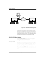
1
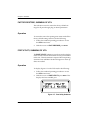
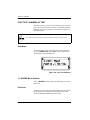
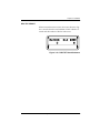
Nx/DBU
Plug-On Board
Option Module
User Manual
Part Number
1200174L1
June 2000
61200174L1-1B
901 Explorer Boulevard
P.O. Box 140000
Huntsville, AL 35814-4000
Phone: (256) 963-8000
© 2000 ADTRAN, Inc.
All rights reserved.
Printed in USA.
Notes provide additional useful information.
Cautions signify information that could prevent service interruption
Warnings provide information that could prevent damage to the
equipment or endangerment to human life.
iii
Federal Communications Commission Radio Frequency Interference
Statement
This equipment has been tested and found to comply with the limits for a Class A
digital device, pursuant to Part 15 of the FCC Rules. These limits are designed to
provide reasonable protection against harmful interference when the equipment
is operated in a commercial environment. This equipment generates, uses, and
can radiate radio frequency energy and, if not installed and used in accordance
with the instruction manual, may cause harmful interference to radio frequencies.
Operation of this equipment in a residential area is likely to cause harmful interference in which case the user will be required to correct the interference at his
own expense.
Shielded cables must be used with this unit to ensure compliance with Class A
FCC limits.
Changes or modifications to this unit not expressly approved by
the party responsible for compliance could void the user’s authority to operate the equipment.
Warranty and Customer Service
ADTRAN will replace or repair this product within five (5) years from the date of
shipment if it does not meet its published specifications or fails while in service.
For detailed warranty, repair and return information See the ADTRAN Equipment Warranty and Repair and Return Policy Procedure.
Return Material Authorization (RMA) is required prior to returning equipment to
ADTRAN.
For Service, RMA requests, or more information, contact ADTRAN Technical
Support listed on the inside back page of this manual.
iv
LIMITED PRODUCT WARRANTY
ADTRAN warrants that for five (5) years from the date of shipment to Customer, all products manufactured by ADTRAN will be free from defects in
materials and workmanship. ADTRAN also warrants that products will conform to the applicable specifications and drawings for such products, as contained in the Product Manual or in ADTRAN's internal specifications and
drawings for such products (which may or may not be reflected in the Product
Manual). This warranty only applies if Customer gives ADTRAN written
notice of defects during the warranty period. Upon such notice, ADTRAN will,
at its option, either repair or replace the defective item. If ADTRAN is unable,
in a reasonable time, to repair or replace any equipment to a condition as warranted, Customer is entitled to a full refund of the purchase price upon return of
the equipment to ADTRAN. This warranty applies only to the original purchaser and is not transferable without ADTRAN's express written permission.
This warranty becomes null and void if Customer modifies or alters the equipment in any way, other than as specifically authorized by ADTRAN.
EXCEPT FOR THE LIMITED WARRANTY DESCRIBED ABOVE, THE FOREGOING CONSTITUTES THE SOLE AND EXCLUSIVE REMEDY OF THE CUSTOMER AND THE EXCLUSIVE LIABILITY OF ADTRAN AND IS IN LIEU OF
ANY AND ALL OTHER WARRANTIES (EXPRESSED OR IMPLIED). ADTRAN SPECIFICALLY DISCLAIMS ALL OTHER WARRANTIES, INCLUDING
(WITHOUT LIMITATION), ALL WARRANTIES OF MERCHANTABILITY
AND FITNESS FOR A PARTICULAR PURPOSE. SOME STATES DO NOT
ALLOW THE EXCLUSION OF IMPLIED WARRANTIES, SO THIS EXCLUSION MAY NOT APPLY TO CUSTOMER.
In no event will ADTRAN or its suppliers be liable to Customer for any incidental, special, punitive, exemplary or consequential damages experienced by
either Customer or a third party (including, but not limited to, loss of data or
information, loss of profits, or loss of use). ADTRAN is not liable for damages
for any cause whatsoever (whether based in contract, tort, or otherwise) in
excess of the amount paid for the item. Some states do not allow the limitation
or exclusion of liability for incidental or consequential damages, so the above
limitation or exclusion may not apply to Customer.
v
vi
Table of Contents
List of Figures ............................................................................................................ xi
List of Tables ........................................................................................................... xiii
Chapter 1. Introduction...........................................................................................1-1
Nx/DBU V.35 Plug-on Board Overview ..............................................................1-1
Functional Description ............................................................................................1-2
Features ................................................................................................................1-2
Nx Features ..................................................................................................1-2
DBU Features ..............................................................................................1-2
Features Common to the Nx and the DBU .............................................1-3
Interfaces ......................................................................................................1-3
Specifications of the Nx/DBU .................................................................................1-4
Specifications: Nx56/64 (DCE Interface)........................................................1-4
Specifications: Nx/DBU (DTE Interface) ........................................................1-5
Specifications: Nx56/64 and DBU...................................................................1-5
Physical Description .................................................................................................1-6
Chapter 2. Installation.............................................................................................2-1
Unpack & Inspect ......................................................................................................2-1
ADTRAN Shipments Include ...........................................................................2-1
Customer Provides .............................................................................................2-1
Attaching The Plug-on Board ..................................................................................2-2
Placement of the Plug-on Board .......................................................................2-2
Wiring .........................................................................................................................2-3
Power-Up Testing and Initialization ......................................................................2-7
Chapter 3. Installation.............................................................................................3-1
Overview ....................................................................................................................3-1
Front Panel Indicators/Buttons ........................................................................3-1
Menu Structure ...................................................................................................3-1
Nx/DBU Menus Are All Submenus ................................................................3-2
61200174L1-1
Nx/DBU Plug-On Board User Manual
vii
Table of Contents
Operation .....................................................................................................3-2
PORT Status, Submenu of Status ...........................................................................3-4
Operation.............................................................................................................3-4
Nx/DBU Status Menu Options ........................................................................3-5
DTE DATA/CLOCK .................................................................................3-5
DTE STATUS ..............................................................................................3-5
DTE PORT RATE .......................................................................................3-5
DBU DATA/CNTRL .................................................................................3-5
DBU CONTROL .........................................................................................3-6
DBU STATUS ..............................................................................................3-6
PORT CONFIG, Submenu of CONFIG .................................................................3-7
Operation.............................................................................................................3-7
Nx56/64 CONFIG Menu Options ...................................................................3-8
DS0 RATE ....................................................................................................3-8
TX CLK CNTRL ..........................................................................................3-8
DATA ...........................................................................................................3-8
CTS ...............................................................................................................3-9
DCD ..............................................................................................................3-9
DSR ...............................................................................................................3-9
0 INHIB ........................................................................................................3-9
INBAND MODE .........................................................................................3-9
DBU CONFIG Menu Options.........................................................................3-10
BACKUP MODE ......................................................................................3-10
SINGLE END FAILURE ................................................................... 3-11
BOTH END FAILURE ...................................................................... 3-11
BACKUP ON ............................................................................................3-11
NET FAIL ........................................................................................... 3-11
NET/DATA FAIL ............................................................................. 3-11
PATTERN VERIFY ...................................................................................3-12
BACKUP DELAY .....................................................................................3-12
RESTORE DELAY ....................................................................................3-12
RETRY DELAY .........................................................................................3-12
NUM RETRIES .........................................................................................3-12
BACKUP TESTING ..................................................................................3-12
BACKUP TEST .................................................................................. 3-13
TEST HOUR ....................................................................................... 3-13
TEST DAY .......................................................................................... 3-13
WKEND LOCKOUT ................................................................................3-13
A) ENABLE HR: (0-23) ...........................................................................3-13
B) DISABLE HR: (0-23) ...........................................................................3-13
C) Trap in DBU .........................................................................................3-13
FACTORY RESTORE, Submenu of UTIL ...........................................................3-14
viii
Nx/DBU Plug-On Board User Manual
61200174L1-1
Table of Contents
Operation ...........................................................................................................3-14
PORT UTILITY, Submenu of UTIL ......................................................................3-14
Operation ...........................................................................................................3-14
RUN SELF-TEST, Submenu of TEST ....................................................................3-15
PORT TEST, Submenu of TEST ............................................................................3-16
Operation ...........................................................................................................3-16
1.1 Nx/DBU Menu Options ............................................................................3-16
PRT/LOCAL .............................................................................................3-16
REMOTE .............................................................................................3-17
REM V.54 CONT ...............................................................................3-17
OFF ......................................................................................................3-17
511 PATT ....................................................................................................3-17
ON .......................................................................................................3-17
OFF ......................................................................................................3-17
511 RESULTS .............................................................................................3-18
DBU LOOPBACK .....................................................................................3-18
DBU TEST ..................................................................................................3-18
TESTS OFF ..........................................................................................3-18
FORCED BACKUP ............................................................................3-18
INTERFACE TST ...............................................................................3-18
DBU DATA/CNTRL ................................................................................3-18
DBU TST RESULT ....................................................................................3-19
Appendix A. System Messages ........................................................................... A-1
Index ....................................................................................................................Index-1
61200174L1-1
Nx/DBU Plug-On Board User Manual
ix
Table of Contents
x
Nx/DBU Plug-On Board User Manual
61200174L1-1
List of Figures
Figure 1-1. Nx/DBU Plug-on Board......................................................................1-6
Figure 2-1. Attaching the Plug-on Board ...............................................................2-2
Figure 2-2. Nx/DBU Plug-On Board Cable Assembly ........................................2-5
Figure 2-3. Nx/DBU Plug-On Board Cable Schematic........................................2-6
Figure 3-1. TSU 100 Main Menu Tree .....................................................................3-2
Figure 3-2. Nx/DBU Plug-On Board Menu Tree ..................................................3-3
Figure 3-3. Port Status Submenu.............................................................................3-4
Figure 3-4. DBU Status Submenu ...........................................................................3-6
Figure 3-5. Port Configuration Submenu ..............................................................3-7
Figure 3-6. Inband Remote Configuration...........................................................3-10
Figure 3-7. Port Utility Submenu..........................................................................3-14
Figure 3-8. Port Name and Software Version Display .......................................3-15
Figure 3-9. Port Test Submenu ..............................................................................3-16
Figure 3-10. DBU TST Result Submenu ...............................................................3-19
61200174L1-1
Nx/DBU Plug-On Board User Manual
xi
List of Figures
xii
Nx/DBU Plug-On Board User Manual
61200174L1-1
List of Tables
Table 2-1. Nx/DBU Pin Connection...................................................................... 2-3
Table 2-2. DBU V.35 Winchester Pin Connection................................................ 2-4
Table 3-1. Normal Mode Operation ...................................................................... 3-8
61200174L1-1
Nx/DBU Plug-On Board User Manual
xiii
List of Tables
xiv
Nx/DBU Plug-On Board User Manual
61200174L1-1
Introduction
Chapter 1
NX/DBU V.35 PLUG-ON BOARD OVERVIEW
The Nx/DBU V.35 plug-on board is available for use with
any option module with the following TSU units:
•
TSU 100
•
TSU 120
•
TSU 600
•
TSU 610
The Nx/DBU V.35 plug-on board installs on any option
module in the option slot of the TSU units and provides
an additional synchronous V.35 interface port with dial
backup capability. When used in these products, this interface port allows an additional DTE to have access to
the T1 service with dial backup capability in the event of
a T1 failure.
The Nx/DBU plug-on board has a special Y cable that it
uses to break apart the Nx and DBU ports from the single
V.35 connector. The longer (2 ft.) side of the Y, with the
male connector, provides connection to the DBU. The
shorter (1 ft.) side, with the female connector, provides access to the Nx port.
In the remainder of this manual, the board will be called
the Nx/DBU plug-on board.
61200174L1-1
Nx/DBU Plug-on Board User Manual
1-1
Chapter 1. Introduction
FUNCTIONAL DESCRIPTION
The Nx/DBU plug-on board operates on an option module of the TSU units and is under the control of the TSU.
The Nx/DBU plug-on board is configured from the front
panel or by an external PC program. The internal menus
for their configuration are part of the Nx/DBU plug-on
board and are automatically installed when the Nx/DBU
is installed in a TSU unit.
Features
Nx Features
The general features of the Nx are listed below:
•
Data rates from 56 kbps to 2.048 mbps in 56K or 64K
increments
•
Includes an elastic store for adsorption of rate variations
•
Executes and responds to V.54 looping codes
•
Outputs a 50% duty cycle output clock at all rates
•
Provides an inband control channel (8 kbps for network management communication)
•
Generates and checks 511 test pattern toward network
•
511 pattern generator is capable of injecting errors
DBU Features
The following are general features of the DBU:
1-2
•
Capable of verifying integrity of dial up network with
a test pattern without disrupting T1 data
•
Detect no data transitions on the data received from
the network, with verify over inband channel
•
User definable delay between call retries if backup
connection is not successfully established
Nx/DBU Plug-on Board User Manual
61200174L1-1
Chapter 1. Introduction
•
User definable verification of dial up network (daily,
weekly, or on command) without T1 data disruption
•
Backup can be initiated by:
- Alarm conditions on network (AIS, RAI, or Red
Alarm)
- Absence of data transitions for a user-defined delay
- Uses 8 kbps channel to check end-to-end connectivity before activating backup
- Disable backup based on hour of day and weekend
- Uses pattern to validate backup dial network
Features Common to the Nx and the DBU
The following features are common to the Nx and the
DBU:
•
Configurable by using a PC program (T-Watch)
•
Menu operation for easy configuration
•
Performs self-test of option card hardware
•
Install multiple Nx/DBU modules in a TSU 600
•
Hot swappable
Interfaces
The following interfaces are used with the Nx/DBU:
61200174L1-1
•
Two CCITT V.35 electrical (differential)
•
One V.35 Winchester connector
Nx/DBU Plug-on Board User Manual
1-3
Chapter 1. Introduction
SPECIFICATIONS OF THE NX/DBU
Specifications: Nx56/64 (DCE Interface)
1-4
DCE Interface
CCITT V.35 synchronous
Rates
56 kbps to 2.048 mbps in 56K or
64K increments
Clock Options
Internal or internal-invert
Tests
Local loopback (bilateral)
Remote loopback (V.54)
Test Pattern
511 with errored seconds display
and error inject capability
Data Inversion
Menu selectable
1s Density
Protection
Force 1s to network after one
second of consecutive zeros
from DTE User selectable (On/
Off)
CTS, DCD, DSR
Normal or Force On
Connector
Winchester (V.35), female
Nx/DBU Plug-on Board User Manual
61200174L1-1
Chapter 1. Introduction
Specifications: Nx/DBU (DTE Interface)
DTE Interface
CCITT V.35 synchronous
Backup Delay
1 sec, 3 sec, 10 sec, 30 sec,
1 min, 5 min, 10 min
DBU Dialing
DTR dialing
Restore Delay
1 sec, 3 sec, 10 sec, 30 sec,
1 min, 5 min, 10 min, Never
Rates
56 kbps through 2.048 mbps
in 56K or 64K increments
Clocking
Routes external DCE clocks
to external DTE when active
Connector
Winchester (V.35) female
Test
Loopback to DCE
Test dialup network
Force dial backup
Specifications: Nx56/64 and DBU
61200174L1-1
Mechanical
Mechanically compatible with
option slot of all TSUs
Environmental
Operating temperature from 0°C
to 45°C
Tests
Extensive self-test
Nx/DBU Plug-on Board User Manual
1-5
Chapter 1. Introduction
PHYSICAL DESCRIPTION
The Nx/DBU plug-on board plugs onto any option module used by the TSU family of products (see Figure 1-1).
The PORT X.2/3 indication is linked to the port numbering philosophy of the TSU product family. The X represents the slot number into which the plug-on board is
plugged. The 2/3 indicates which port the plug-on board
occupies. The port number will be 2 or 3, depending on
the option module used.
The TSU 100 has one option slot; therefore the port designation is 1.2/3.
The TSU 120 has one option slot; therefore the port designation is 1.2/3.
The TSU 600 and the TSU 610 each have six option slots;
therefore the port numbers would be port 1.2/3 to port
6.2/3. The numbers appear in the front panel LCD menu
display.
Figure 1-1. Nx/DBU Plug-on Board
1-6
Nx/DBU Plug-on Board User Manual
61200174L1-1
Installation
Chapter 2
UNPACK & INSPECT
Carefully inspect the plug-on board for any shipping
damage. If damage is suspected, file a claim immediately
with the carrier and then contact ADTRAN customer service. If possible, keep the original shipping container for
use in shipping the plug-on board back for repair or for
verification of damage during shipment.
ADTRAN Shipments Include
•
The Nx/DBU Plug-on Board
•
The Nx/DBU Plug-on Board User Manual (to be inserted into main TSU user manual)
•
The Y cable used to break apart the V.35 and DBU
connections
Customer Provides
61200174L1-1
•
DTE cable
•
DCE cable
Nx/DBU Plug-on Board User Manual
2-1
Chapter 2. Installation
ATTACHING THE PLUG-ON BOARD
Placement of the Plug-on Board
Figure 2-1 shows the proper placement of the plug-on
board to the option module. Perform the following steps
to install the plug-on board:
1.
Hold the plug-on board above the option module.
2.
Using a downward and right to left motion, slip the
V.35 connector plug into the opening in the option
module back panel.
3.
Moving the plug-on board downward, secure the
connection of the header pins at the front of the
boards.
4.
Install the two 4-40 screws at both edges of the
option module.
NX 56/64
PORT X.1
V.35
NX 56/64
PORT X.1
V.35
Figure 2-1. Attaching the Plug-on Board
The connection of the header pins between the option module and the
plug-on board must be visually verified. Improper connections can
severely damage the equipment.
2-2
Nx/DBU Plug-on Board User Manual
61200174L1-1
Chapter 2. Installation
WIRING
The Nx/DBU plug-on board has one V.35 Winchesterstyle connection. The Nx and DBU connection is defined
in Table 2-1, below, and Table 2-2 on page 2-4.
Table 2-1. Nx/DBU Pin Connection
Pin
CCITT
A
101
Protective ground (PG)
B
102
Signal ground (SG)
C
105
Request to send (RTS) from DTE
D
106
Clear to send (CTS) to DTE
E
107
Data set ready (DSR) to DTE
F
109
Received line signal detector (DCD) to DTE
R
104
Received data (RD-A)
T
104
Received data (RD-B)
V
115
RX clock (RC-A) to DTE
X
115
RX clock (RC-B) to DTE
P
103
Transmitted data(TD-A) from DTE
S
103
Transmitted data(TD-B) from DTE
Y
114
TX clock (TC-B) to DTE
AA
114
TX clock (TC-B) to DTE
U
113
External TX Clock (TC-A) from DTE
W
113
External TX clock (ETC-B) from DTE
NN
-
61200174L1-1
Description
Test mode (TM) to DTE
Nx/DBU Plug-on Board User Manual
2-3
Chapter 2. Installation
Table 2-2. DBU V.35 Winchester Pin Connection
2-4
Pin
CCITT
Description
A
101
Protective ground (PG)
B
102
Signal ground (SG)
J
105
Request to send (RTS) from DCE
M
106
Clear to send (CTS) from DCE
N
107
Data set ready (DSR) from DCE
BB
109
Received line signal detector (DCD) from DCE
MM
-
Data terminal ready (DTR) to DCE
Z
-
Ring indicator (RI) from DCE
DD
104
Received data (FD-B) from DCE
FF
104
Received data (RD-B) from DCE
HH
115
RX clock (R-B) from DCE
JJ
115
RX clock (RC-B) from DCE
CC
103
Transmitted data (TD-A) to DCE
EE
103
Transmitted data (TD-B)
KK
114
TX Clock (TC-A) from DCE
LL
114
TX clock (TC-B) from DCE
Nx/DBU Plug-on Board User Manual
61200174L1-1
Chapter 2. Installation
The Nx/DBU Plug-on board cable assembly is shown in
Figure 2-2. The schematic for this cable assembly is shown
in Figure 2-3 on page 2-6.
1 FT
NX
V.35
FEMALE
A
24 or 26 AWG ea. plus shielding
V.35
MALE
DBU
V.35
MALE
B
2 FT
Figure 2-2. Nx/DBU Plug-On Board Cable Assembly
61200174L1-1
Nx/DBU Plug-on Board User Manual
2-5
Chapter 2. Installation
JP2
FG
SG
RTS
CTS
DSR
RLSD
TM
TD-A
RD-A
TD-B
RD-B
ETC-A
RC-A
ETC-B
RC-B
TC-A
JP1
V.35
MALE
1
2
3
4
5
6
7
8
9
10
11
12
13
14
15
16
17
18
19
20
21
22
23
24
25
26
27
28
29
30
31
32
33
34
TC-B
FG
SG
RTS
CTS
DSR
RLSD
RTS2
TM
CTS2
DSR2
TD-A
RD-A
TD-B
RD-B
ETC-A
RC-A
ETC-B
RC-B
TC-A
RI
TC-B
DCD2
TD-A2
RD-A2
TD-B2
RD-B2
RC-A2
RC-B2
TC-A2
TC-B2
DTR2
TM
TM
1
2
3
4
5
6
7
8
9
10
11
12
13
14
15
16
17
18
19
20
21
22
23
24
25
26
27
28
29
30
31
32
33
34
NX
V.35
A
FEMALE
(1 FT)
JP3
FG
SG
RTS2
CTS2
DSR2
DCD2
DTR2
RI
TD-A2
RD-A2
TD-B2
RD-B2
RC-A2
RC-B2
TC-A2
TC-B
1
2
3
4
5
6
7
8
9
10
11
12
13
14
15
16
17
18
19
20
21
22
23
24
25
26
27
28
29
30
31
32
33
34
DBU
V.35
B
MALE
(2 FT)
Figure 2-3. Nx/DBU Plug-On Board Cable Schematic
2-6
Nx/DBU Plug-on Board User Manual
61200174L1-1
Chapter 2. Installation
POWER-UP TESTING AND INITIALIZATION
The plug-on board executes a self-test during the powerup sequence, as described in the TSU manual. No initialization input is required. Upon power-up, any previously configured setting for the plug-on board is
automatically restored.
When self-testing is completed and configuration is successfully restored, the LED labeled OK in the MODULE
group on the front panel turns ON. If any alarms are detected during operation, the red LED labeled ALARM in
the MODULE group on the front panel turns ON.
For more information about the front panel, see the Operation chapter of the appropriate TSU user manual.
61200174L1-1
Nx/DBU Plug-on Board User Manual
2-7
Chapter 2. Installation
2-8
Nx/DBU Plug-on Board User Manual
61200174L1-1
Chapter 3
Installation
OVERVIEW
The Nx/DBU plug-on board is controlled as part of the
TSU using the same methods as described in the appropriate TSU User Manual.
Front Panel Indicators/Buttons
Refer to the description of the TSU front panel indicators
and buttons in the appropriate TSU User Manual.
Menu Structure
The Nx/DBU plug-on board menus appear as a subset of,
and operate the same as, menus for the TSUs. The menus
are accessed by selecting 1.1 Nx/DBU under the PORT
menu items.
The main menu for the TSU 100 is used for illustrative
purposes. The main menus for the other TSU units operate in a similar way. Figure 3-1 on page 3-2 shows the
TSU 100 main menu with the PORT 1.1 Nx/DBU menu
items printed in bold italicized letters.
Complete menu trees for each TSU product is found in
their respective user manuals.
61200174L1-1
Nx/DBU Plug-on Board User Manual
3-1
Chapter 3. Installation
1) NI PERF REPORTS
1) STATUS
2) NI ERRORS
3) ACTIVE ALARMS
1) NETWORK (NI)
2) CONFIG
2) UNIT
4) VIEW HISTORY
5)PORT STATUS
3) MAP XCHNG
TSU 100
4) MAP IN USE A(B)
MAIN MENU
5) DS0 MAP A
1) TIME/DATE
6) DS0 MAP B
2) FACTORY RESTORE
7) PORT CONFIG
3 SET PASSCODE
4) UNIT ID
3) UTIL
5) PORT UTILITY
6) SOFTWARE REV
4) TEST
1) NETWORK TESTS
2) RUN SELF-TEST
3) PORT TEST
4) CANCEL TEST
7) ENET ADDRESS
8) SERIAL NUMBER
Figure 3-1. TSU 100 Main Menu Tree
Nx/DBU Menus Are All Submenus
The Nx/DBU plug-on board menus are accessed from
and operated the same as menus for the TSU 100. Menu
items in the main menu in Figure 3-1 printed in bold italics are submenu choices for the Nx/DBU plug-on board.
See Figure 3-2 for the menu tree for each of these submenu options. Each of the these submenu items is discussed in the following paragraphs. All are accessed by
the same method.
Operation
With the cursor on one of the four main menu choices,
press Enter or the number key. The results are the first two
submenu items with the cursor on the first item. Use the
Scroll Down key to place the cursor on the desired item
then press Enter. This displays the first two submenu
choices.
3-2
Nx/DBU Plug-on Board User Manual
61200174L1-1
Chapter 3. Installation
1 STATUS
5) PORT STATUS
1) DTE DATA/CLOCK
1) DS0 RATE
2) DTE STATUS
2) TX CLK CNTRL
3) DTE PORT RATE
3) DATA
4) DBU DATA/CNTRL
4) CTS
5) DBU CONTROL
5) DCD
6) DBU STATUS
6) DSR
7)0 INHIB
1) NX56/64 CONFIG
2) CONFIG
8)INBAND MODE
7) PORT CONFIG
2) DBU CONFIG
1) BACKUP MODE
2) BACKUP ON
2)FACTORY RESTORE
3) PATTERN VERIFY
NX/DBU
MENU
4) BACKUP DELAY
3) UTIL
5) PORT UTILITY
SW REV
5) RESTORE DELAY
6) RETRY DELAY
7) NUM RETRIES
1) BACKUP TEST
8) BACKUP TESTING
2) TEST HOUR
9) WKEND LOCKOUT
3) TEST DAY
A) ENABLE HR
B) DISABLE HR
2) RUN SELF-TEST
4)TEST
1) DTE LOOPBACK
3) PORT TEST
1.1 Nx/DBU
2) 511 PATT
3) 511 RESULTS
4) DBU LOOPBACK
5) DBU TEST
6) DBU DATA/CNTRL
7) DBU TST RESULT
Figure 3-2. Nx/DBU Plug-On Board Menu Tree
The Nx/DBU plug-on board menu tree selections are discussed on the following pages.
61200174L1-1
Nx/DBU Plug-on Board User Manual
3-3
Chapter 3. Installation
PORT STATUS, SUBMENU OF STATUS
The Status menu branch provides the ability to view the
status of the TSU 100 operation. It displays the status of
the monitored signal line on the Nx/DBU plug-on board
and the data rate for which the plug-on board is configured.
Operation
To display Figure 3-3 on the TSU 100, place the cursor on
STATUS and do the following:
1.
Press Enter or the number 1 key. This displays the
first two Status submenu items with the cursor on
NI PERF RPTS.
2.
Use the Scroll Down key to place the cursor on
PORT STATUS and press Enter. This displays the
first available port.
3.
Use the scroll keys to identify 1.1 NX/DBU and press
Enter.
Figure 3-3. Port Status Submenu
The base Nx interface shows the status screens listed in
this manual. For other plug-on boards, refer to the appropriate TSU User Manual.
3-4
Nx/DBU Plug-on Board User Manual
61200174L1-1
Chapter 3. Installation
Nx/DBU Status Menu Options
Select 1.1 NX/DBU. The following five menu options are
available:
DTE DATA/CLOCK
Shows the status (active or not active) of the following
lines:
TXD
Transmit data to the DTE
RXD
Receive data from the DTE
ETC
External transmit clock from DTE
LCK
Lock status of the phase locked loop
DTE STATUS
Shows the status (active or not active) of the following
lines:
RTS
Request to send from DTE
CTS
Clear to send to DTE
DCD
Data carrier detect to DTE
DSR
Data set ready to DTE
DTE PORT RATE
Displays the data rate to which the Nx port is set.
DBU DATA/CNTRL
Shows the status (active or not active) of the following
lines:
61200174L1-1
TXD
Transmit data to the DCE
RXD
Receive data from the DCE
DCD
Data carrier detect from DCE
RI
Ring indicate from DCE
Nx/DBU Plug-on Board User Manual
3-5
Chapter 3. Installation
DBU CONTROL
Shows the status (active or not active) of the following
lines:
RTS
Request to send to DCE
CTS
Clear to send from DCE
DTR
Data terminal ready to DCE
DSR
Data set ready from DCE
DBU STATUS
Shows current backup state (see Figure 3-4).
Figure 3-4. DBU Status Submenu
DBU SECS
Total seconds the plug-on board has
been in backup.
IN DBU - YES
Module is in backup mode.
- NO
Module is not in backup mode
Exit the displays as described in the appropriate TSU User
Manual.
3-6
Nx/DBU Plug-on Board User Manual
61200174L1-1
Chapter 3. Installation
PORT CONFIG, SUBMENU OF CONFIG
The PORT CONFIG submenu is used for configuration of
the Nx/DBU plug-on board.
Operation
To display Figure 3-5 on the TSU 100, place the cursor on
CONFIG and do the following:
1.
Press Enter or the number 2 key. This displays the
first two Configuration submenu items with the cursor on NETWORK (NI).
2.
Use the Scroll Down key to place the cursor on PORT
CONFIG and press Enter.
3.
Use the scroll keys to identify the 1.1 NX/DBU plugon board. Only the bottom line of the display
changes.
Figure 3-5. Port Configuration Submenu
To select PORT CONFIGURATION, press Enter. This displays
the following menu options:
•
Nx56/64 CONFIG
•
DBU CONFIG
Place the cursor over the desired option and press Enter
to configure. Menu options for the Nx56/64 and the DBU
are shown on the following pages.
61200174L1-1
Nx/DBU Plug-on Board User Manual
3-7
Chapter 3. Installation
Nx56/64 CONFIG Menu Options
Select the NX56/64 menu option to access the following
eight menu options:
DS0 RATE
This sets the base rate of the interface. The actual data rate
depends on the number of DS0s assigned to the DTE Data
Rate Chart in the appropriate TSU User Manual.
Choices - 56K or 64K
TX CLK CNTRL
Controls the clock used by the TSU 100 to accept the transmit (TX) data from the DTE. Normally this is set to INTERNAL. If the interface cable is long, causing a phase shift in
the data, the clock can be selected as INT/INV (INTERNAL/INVERTED). This switches the phase of the clock which
should compensate for a long cable.
Choices - Normal or Invert
DATA
Used to control the inverting of the DTE data. This inversion can be useful when operating with a high level data
link (HDLC) protocol. Often used as a means to ensure 1s
density.
Choices - Normal or Invert
Table 3-1 shows the conditions which cause the port control signal to be deactivated.
Table 3-1. Normal Mode Operation
Signal
RTS
V.54
511 Test Self-Test Network Test
Loopback
On
Active
Active
NO DS0
Mapped
Network
Alarm*
CTS
Follows
Off
Off
Off
Off
Off
Off
DCD
-
-
-
Off
-
Off
Off
DSR
-
Off
Off
Off
Off
Off
-
- Do not care
* Until backup becomes active
3-8
Nx/DBU Plug-on Board User Manual
61200174L1-1
Chapter 3. Installation
CTS
Used to control characteristics of CTS.
Choices - Normal or Force On (see Table 3-1 on page 3-8).
DCD
Data Carrier Detect - Indicates to the DTE when a valid
signal is being received at the Network Interface.
Choices - Normal or Force On (see Table 3-1 on page 3-8).
DSR
Data Set Ready - This signal indicates to the DTE when
the DCE is turned on and ready for operation.
Choices - Normal or Force On (see Table 3-1 on page 3-8).
0 INHIB
If the Nx interface detects an uninterrupted string of -0s
being transmitted toward the network, and if 0s are transmitted for more than one second, then the TSU 100 forces
1s towards the network.
Choices - On or Off
INBAND MODE
Inband Configuration Channel - Used to enable/disable
an 8 kbps remote configuration channel (see Figure 3-6 on
page 3-10).
When this option is set to On, the first DS0 mapped to the
Nx interface operates in 56K mode and the DTE clock rate
is reduced by 8 kbps. The TSU uses this 8 kbps channel to
send and receive configuration data across a T1 span. As
shown in Figure 3-6, this allows the PC connected to the
chain-in port on TSU 600 A to monitor/configure both
TSU 600 A and B. This feature is useful when FDL connectivity is not available across the T1 span.
This 8 kbps channel is only taken out of the first DS0. If
two 64K DS0s are mapped, the DTE rate would be 120
kbps instead of 128 kbps.
61200174L1-1
Nx/DBU Plug-on Board User Manual
3-9
Chapter 3. Installation
T-WATCH
TSU 600 B
TSU 600 A
CHAIN IN
NETWORK
NX/DBU
ROUTER
NX/DBU
PBX
PBX
ROUTER
PBX
PBX
Figure 3-6. Inband Remote Configuration
If the inband configuration channel is enabled, the Nx/
DBU will use the channel to verify end-to-end connectivity of the T1 network. This provides more robust monitoring of the primary network. This is especially useful in
networks where alarms are not passed end-to-end.
DBU CONFIG Menu Options
Select the DBU CONFIG menu option to access the 11
menu options discussed in this section.
BACKUP MODE
The DBU can activate backup in two basic modes: SINGLE END FAILURE or BOTH END FAILURE. These can
be used to control how calls are established and which
end initiates the dialing process.
Choices: DISABLE, ORIGINATE, ANSWER, ORIG/ANS
ANY
3-10
Nx/DBU Plug-on Board User Manual
61200174L1-1
Chapter 3. Installation
SINGLE END FAILURE
In this mode, a backup condition detected at either end
of the circuit causes a backup to be activated. The DBU
at the failed end initiates a call to the opposite end which
goes into backup mode upon receiving a call. This is particularly useful for Fractional T1 applications where a
failure at one end cannot be reported to the other end.
Choices: Mode: ORIG/ANS ANY
In this mode, if the unit has Pattern Verify turned Off, it will go into
backup mode on any received call, even a wrong number.
BOTH END FAILURE
In this mode, both ends of the circuit must detect backup
conditions before backup is activated. One DBU is set to
ORIGINATE and the other to ANSWER. Upon a network failure, only the Originate DBU initiates backup by
dialing the Answer end. Once called, the Answer DBU
goes into backup mode only if a backup condition is
detected. This is ideal for controlling where calls originate.
Choices: Mode: ORIGINATE or ANSWER
BACKUP ON
This selects the conditions that cause the Nx/DBU to initiate Backup.
Choices: NET FAIL, NET/DATA FAIL
NET FAIL
Backup occurs on RED ALARM, YELLOW ALARM,
BLUE ALARM, AND LOS.
NET/DATA FAIL
Backup occurs on the same conditions as NET FAIL plus
loss of data transitions on the data the Nx56/64 receives
from the network.
61200174L1-1
Nx/DBU Plug-on Board User Manual
3-11
Chapter 3. Installation
PATTERN VERIFY
This selects whether or not the DBU will use its pattern
generator and receiver to authenticate backup attempts.
When the local and remote units are both Nx/DBUs, set
this to Enable; otherwise set this to disable.
Choices: ENABLE, DISABLE
BACKUP DELAY
This selects the time allowed to elapse between the network going into alarm or no data transmissions and the
backup beginning.
Choices: 1 sec, 3 sec, 10 sec, 30 sec, 1 min, 5 min, 10 min
RESTORE DELAY
This selects the time that elapses between the network going out of alarm or data and the backup call being taken
down. If never is selected, the user must deactivate the
backup mode.
Choices: 1 sec, 3 sec, 10 sec, 30 sec, 1 min, 5 min, 10 min,
never
RETRY DELAY
This selects the time between redialing the external DCE
after failed dial attempts.
Choices: 10 sec, 30 sec, 1 min, 5 min, 10 min
NUM RETRIES
This selects the number of times the DBU will attempt to
redial if unable to connect.
Choices: none, unlimited, 3 times, 10 times
BACKUP TESTING
This submenu sets the options for the automatic ISDN
BACKUP TESTING:
This submenu sets the options for the automatic ISDN
verification feature of the Nx/DBU. Verification of the
backup circuit does not disrupt data on the T1.
3-12
Nx/DBU Plug-on Board User Manual
61200174L1-1
Chapter 3. Installation
BACKUP TEST
This selects the frequency of automatic backup circuit
verification by the DBU.
Choices: MANUAL, HOURLY, DAILY, WEEKLY
TEST HOUR
This selects the hour of the day the backup test will
occur.
Choices: 0 to 23
TEST DAY
If weekly backup test is selected, this option will select
which day to perform the test.
Choices: MONDAY through SUNDAY
WKEND LOCKOUT
If no backup is desired from midnight Friday to midnight Sunday, set this selection to ON, otherwise set to
OFF.
Choices: ON, OFF
A) ENABLE HR: (0-23)
The hour that the backup will be enabled can be entered
from the numeric keyboard.
B) DISABLE HR: (0-23)
The hour that the backup will be disabled can be entered
from the numeric keypad.
For items A and B to function properly, verify that the time and date in
the TSU are set correctly. Consult the appropriate TSU User Manual for
instructions on setting date and time.
C) Trap in DBU
If traps are enabled (see unit configurations), this parameter will send either a single trap upon going into a DBU
session or send repeated traps for the duration of the
DBU session.
Choices: Single, Repeated
61200174L1-1
Nx/DBU Plug-on Board User Manual
3-13
Chapter 3. Installation
FACTORY RESTORE, SUBMENU OF UTIL
This selection is used to restore the factory default settings for all pass-through plug-on board parameters.
Operation
To return the unit to the opening main menu with all the
factory default settings restored, do the following:
1.
Follow the standard operating procedure to access
the UTIL menu items.
2.
With the cursor on FACT RESTORE, press Enter.
PORT UTILITY, SUBMENU OF UTIL
The PORT UTILITY submenu is used to access the display
of the current software information for each port installed
in the unit. This information is required when requesting
assistance from ADTRAN Technical Support or when updates are needed.
Operation
To display Figure 3-7 on the TSU 100, do the following:
1.
Follow the standard operating procedure to access
the UTIL menu items.
2.
With the cursor on PORT UTILITY, press Enter. This
displays the first available port.
5
Figure 3-7. Port Utility Submenu
3-14
Nx/DBU Plug-on Board User Manual
61200174L1-1
Chapter 3. Installation
To display the port name and the software version installed as shown in Figure 3-8, do the following:
1.
Use the scroll keys to move through the available
ports, or enter the port number with the number key.
2.
When the desired port name is displayed, press
Enter.
3.
Press Cancel to exit or to select another port.
Figure 3-8. Port Name and Software Version Display
RUN SELF-TEST, SUBMENU OF TEST
This menu item is used to execute both the internal test of
the TSU and of the Nx/DBU. The results of the self-test
are shown on the TSU display. For additional information on self-test, see the Operation chapter of the appropriate TSU user manual.
To activate a self-test, do the following:
61200174L1-1
1.
Follow the standard operating procedure to access
the TEST menu items.
2.
With the cursor on RUN SELF TEST, press Enter.
The TSU display shows the test outcome.
Nx/DBU Plug-on Board User Manual
3-15
Chapter 3. Installation
PORT TEST, SUBMENU OF TEST
This menu item is used to activate testing of specific data
ports. It also controls the activation of loopbacks and the
initiation of data test patterns. Test results are shown on
the TSU display.
Port Test execution disrupts normal data flow in the port being tested.
Operation
To display Figure 3-9 on the TSU 100, starting with the
cursor on PORT TEST, press Enter or the number 3 key.
This displays the available ports.
3
Figure 3-9. Port Test Submenu
1.1 Nx/DBU Menu Options
The 1.1 NX/DBU interface offers the following seven test
functions:
PRT/LOCAL
The Nx port activates both a local loopback (back toward
the DTE) and a port loopback when either is invoked.
Choices: REMOTE, REM V.54 CONT, OFF
3-16
Nx/DBU Plug-on Board User Manual
61200174L1-1
Chapter 3. Installation
REMOTE
The remote loopback causes a channelized V.54 code to
be sent to the far end. The Nx at the far end activates a
PORT/LCL loopback on detection of the V.54 code.
REM V.54 CONT
This loopback causes a continuous V.54 code to be sent to
the far end. The Nx at the far end activates a PORT/LCL
loopback on detection of the V.54 code.
OFF
The loop is deactivated.
The TSU checks the remote loopback activation by detecting a proper
response from the remote end. While waiting for the response, the display
shows Looping. If successful, the display changes to Looped Up. If
unsuccessful, it displays Failed.
511 PATT
Activates the generation of the 511 test pattern toward the
T1 network.
Choices: OFF, ON
ON
The pattern check circuitry is enabled and a test started.
The test is ended by selecting OFF.
OFF
The pattern generation and check is disabled.
61200174L1-1
Nx/DBU Plug-on Board User Manual
3-17
Chapter 3. Installation
511 RESULTS
Displays the results of the 511 test indicated in menu selection 511 PATT.
The results are in the form of the number of errored seconds. The error count can be cleared by pressing the Clear
key (Shift + 9). A bit error may be inserted into the data
stream by pressing the 2 key.
DBU LOOPBACK
Activates the generation of the 511 test pattern toward the
T1 network.
Choices: OFF, ON
DBU TEST
This selection is used to force a backup to occur even if a
backup condition does not exist.
Choices: TESTS OFF, FORCED BACKUP, INTERFACE
TST
TESTS OFF
Turns off DBU tests.
FORCED BACKUP
Used to force a backup regardless of time-of-day lockouts or network conditions.
INTERFACE TST
This test causes the external DCE to dial its stored number. After the connection is established the DBU will
send a test pattern to verify the backup network. This
test does not disrupt data or the primary network.
DBU DATA/CNTRL
Allows status of DCD and RI to be monitored while the
INTERFACE TST is on. If the dial up network is correctly
configured and dialed up, there should be an asterisk (*)
over DCD.
3-18
Nx/DBU Plug-on Board User Manual
61200174L1-1
Chapter 3. Installation
DBU TST RESULT
When an interface test is active, the screen shown in Figure 3-10 will show the total number of DATA blocks received and the number of blocks with errors.
Figure 3-10. DBU TST Result Submenu
61200174L1-1
Nx/DBU Plug-on Board User Manual
3-19
Chapter 3. Installation
3-20
Nx/DBU Plug-on Board User Manual
61200174L1-1
System Messages
Appendix A
ALARM MESSAGES
Network Interfaces
Red Alarm
NI unable to align frame with incoming signal
Yellow Alarm
Remote alarm indication (RAI) being received from the
far end
Blue Alarm
Unframed all 1s (AIS) being received at NI
Loss of Signal
No signal detected at NI
Nx/DBU Plug-on Board
Clock Slip
Difference in frequency of the data clock at the network
and DTE
PLL Alarm
Unable to lock phase lock on the clock provided by the
network interface
61200174L1-1
Nx/DBU Plug-on Board User Manual
A-1
Appendix A. System Messages
Zeros Alarm
All 0s data being sent to the network interface
No EXT Clock
No external transmit clock at DTE (when applicable)
STATUS MESSAGES
Network Interfaces
Payload On
Payload loopback activated
Line On
Line loopback activated
Loopback Off
All loopbacks deactivated
Factory Restore
Factory setting restored
Power On
Unit powered on
Self-Test
Internal self-test performed
A-2
Nx/DBU Plug-on Board User Manual
61200174L1-1
Appendix A. System Messages
Nx/DBU Plug-on Board
Loop-Up
Data is looped back at both the network interface and the
DTE interface of the card
Remote Loop Up
Sending a V.54 pattern in an attempt to loop up a remote
device
511 Pattern On
Sending a 511 pattern towards the network interface
Loop Down
Data is no longer looped back at the network interface or
the DTE interface
511 Pattern Off
No longer sending a 511 pattern towards the network
interface
61200174L1-1
Nx/DBU Plug-on Board User Manual
A-3
Appendix A. System Messages
A-4
Nx/DBU Plug-on Board User Manual
61200174L1-1
Index
Numerics
0 INHIB 3-9
1.1 Nx/DBU Menu Options 3-16
1s Density Protection 1-4
511 PATT 3-17
511 Pattern Off A-3
511 Pattern On A-3
511 RESULTS 3-18
A
attaching the plug-on board, how to 2-2
B
BACKUP DELAY 3-12
BACKUP MOD 3-10
backup on 3-11
BACKUP TEST 3-13
BACKUP TESTING 3-12
Blue Alarm A-1
both end failure 3-11
DBU LOOPBACK 3-18
DBU STATUS 3-6
DBU TEST 3-18
DBU TST RESULT 3-19
DBU V.35 pinout 2-4
DCD 3-9
DCE Interface 1-4
DISABLE HR
(0-23) 3-13
DS0 RATE 3-8
DSR 3-9
DTE DATA/CLOCK 3-5
DTE PORT RATE 3-5
DTE STATUS 3-5
E
ENABLE HR
(0-23) 3-13
Environmental, specifications 1-5
F
C
cables, provided by customer 2-1
Clock Options 1-4
Clock Slip A-1
Connector 1-4
CTS 3-9
Customer Service iv
factory restore, operation 3-14
FACTORY RESTORE, Submenu of UTIL 3-14
FCC Radio Frequency Interference Statement iv
Features, DBU 1-2
Features, Nx 1-2
Features, of both Nx & DBU 1-3
Features, of Nx/DBU plug-on board 1-2
D
I
DATA 3-8
Data Inversion 1-4
DBU CONFIG Menu Options 3-10
DBU CONTROL 3-6
DBU DATA/CNTRL 3-5, 3-18
DBU Features 1-2
INBAND MODE 3-9
indicator buttons, front panel 3-1
installation, overview 3-1
Interfaces & connectors 1-3
items included in shipments 2-1
61200174L1-1
Nx/DBU Plug-On Board User Manual
Index-1
Index
L
Loop Down A-3
Loop-Up A-3
Loss of Signal A-1
port utility, submenu of UTIL 3-14
Power-Up Testing and Initialization 2-7
product warranty v
PRT/LOCAL 3-16
M
R
Mechanical, specifications 1-5
Rates 1-4
Red Alarm A-1
Remote Loop Up A-3
RESTORE DELAY 3-12
RETRY DELAY 3-12
run self-test, submenu of test 3-15
N
NET FAIL 3-11
NET/DATA FAIL 3-11
No EXT Clock A-2
NUM RETRIES 3-12
Nx Features 1-2
Nx/ DBU, DTE interface 1-5
Nx/DBU Menus, about 3-2
Nx/DBU pinouts 2-3
Nx/DBU Plug-on Board A-3
Nx/DBU Plug-on board cable assembly 2-5
Nx/DBU plug-on board cable schematic 2-6
Nx/DBU Plug-On Board Menu Tree 3-3
Nx/DBU plug-on board menus 3-1
Nx/DBU Status Menu 3-5
Nx/DBU V.35 plug-on board 1-1
Nx/DBU, specifications 1-4
Nx56/64 and DBU, common specifications 1-5
Nx56/64 CONFIG Menu Options 3-8
Nx56/64, DCE interface 1-4
P
PATTERN VERIFY 3-12
Physical Description 1-6
pinout, for DBU V.35 2-4
pinouts, for Nx/DBU 2-3
PLL Alarm A-1
PORT CONFIG 3-7
port config, operation 3-7
PORT Status 3-4
port status, operation 3-4
port test, operation 3-16
port test, Submenu of test 3-16
port utility, operation 3-14
Index-2
S
self-test A-2
self-test, to activate 3-15
single end failure 3-11
specification, of Nx/DBU 1-4
Status Message A-2
T
TEST DAY 3-13
TEST HOUR 3-13
Test Pattern 1-4
Tests 1-4
Tests, specificatons 1-5
TSU 100 main menu tree 3-2
TX CLK CNTRL 3-8
U
Unpack & Inspect 2-1
W
Warranty and Customer Service iv
Wiring 2-3
WKEND LOCKOUT 3-13
Y
Yellow Alarm A-1
Z
Zeros Alarm A-2
Nx/DBU Plug-On Board User Manual
61200174L1-1
Product Support Information
Pre-Sales Inquiries and Applications Support
Please contact your local distributor, ADTRAN Applications Engineering, or
ADTRAN Sales:
Applications Engineering
(800) 615-1176
Sales
(800) 827-0807
Post-Sale Support
Please contact your local distributor first. If your local distributor cannot help,
please contact ADTRAN Technical Support and have the unit serial number available.
Technical Support
(888) 4ADTRAN
Repair and Return
If ADTRAN Technical Support determines that a repair is needed, Technical Support will coordinate with the Customer and Product Service (CaPS) department to
issue an RMA number. For information regarding equipment currently in house
or possible fees associated with repair, contact CaPS directly at the following number:
CaPS Department
(256) 963-8722
Identify the RMA number clearly on the package (below address), and return to
the following address:
ADTRAN, Inc.
CaPS Department
6767 Old Madison Pike
Progress Center
Building #6, Suite 690
Huntsville, AL 35807
RMA # _____________