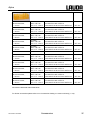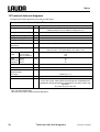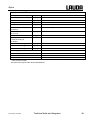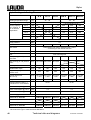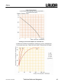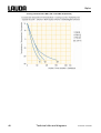
1
Operating Instructions Alpha Immersion Thermostat A Heating Thermostats A 6, A 12, A 24 Cooling Thermostats RA 8, RA 12, RA 24 YACE0084 Valid from series 08-0201 release 10/2009 replaces release 02/2009, 09/2008, 08/2008 LAUDA DR. R. WOBSER GMBH & CO. KG Post office box 1251 97912 Lauda-Königshofen Germany Telephone: 0049 9343/ 503-0 Fax: 0049 9343/ 503-222 E-mail [email protected] Internet http://www.lauda.de Alpha Prefixed safety notes Before operating the equipment please read carefully all the instructions and safety notes. If you have any questions please phone us! Follow the instructions on setting up, operation etc. This is the only way to avoid incorrect operation of the equipment and to ensure full warranty protection. • Transport the equipment with care! Cooling thermostats may NEVER be overturned nor put upside down! • Equipment and its internal parts can be damaged: − by dropping, − by shock. • Equipment must be operated only by technically qualified personnel! • Never operate the equipment without a proper heat transfer liquid! • Never operate the equipment without sufficient water or heat transfer liquid level! • Do not start up the equipment, if: − it is damaged or leaking, − the supply cable is damaged. • Switch off the equipment and pull out the mains plug for: − servicing or repair, − before moving the equipment! • Drain the bath before moving the equipment! • Have the equipment serviced or repaired by properly qualified personnel only! The Operating Instructions include additional safety notes which are identified by a triangle with an exclamation mark. Carefully read the instructions and follow them accurately! Disregarding the instructions may have serious consequences, such as damage to the equipment, damage to property or injury to personnel. We reserve the right to make technical alterations! 29/10/2009/ YACE0084 Prefixed safety notes 3 Alpha Table of content Prefixed safety notes ..................................................................................................................................................... 3 Table of content ............................................................................................................................................................ 4 1 SAFETY NOTES ........................................................................................................................................................ 6 1.1 1.2 GENERAL SAFETY NOTES ....................................................................................................................................... 6 OTHER SAFETY NOTES............................................................................................................................................ 7 2 BRIEF OPERATING INSTRUCTIONS.................................................................................................................. 8 3 CONTROL AND FUNCTIONAL ELEMENTS.................................................................................................... 10 4 UNIT DESCRIPTION.............................................................................................................................................. 14 4.1 4.2 4.3 4.4 4.5 4.6 4.7 4.8 ENVIRONMENTAL CONDITIONS ............................................................................................................................ 14 TYPES OF UNIT ..................................................................................................................................................... 14 BATHS ................................................................................................................................................................. 14 PUMP ................................................................................................................................................................... 14 MATERIALS.......................................................................................................................................................... 15 TEMPERATURE INDICATION, CONTROL AND SAFETY CIRCUIT ............................................................................... 15 REFRIGERATION SYSTEM ..................................................................................................................................... 15 STANDARD ACCESSORIES ..................................................................................................................................... 15 5 UNPACKING............................................................................................................................................................ 16 6 PREPARATIONS ..................................................................................................................................................... 17 6.1 6.2 6.3 6.4 7 ASSEMBLY AND SETTING UP ................................................................................................................................ 17 FILLING AND EMPTYING ....................................................................................................................................... 19 HEAT TRANSFER LIQUIDS AND HOSE CONNECTIONS ............................................................................................. 20 CONNECTION OF EXTERNAL CIRCUITS .................................................................................................................. 21 STARTING UP ......................................................................................................................................................... 22 7.1 CONNECTION TO THE SUPPLY ............................................................................................................................... 22 7.2 SWITCHING ON ..................................................................................................................................................... 23 7.3 GENERAL KEY FUNCTIONS AND PILOT LAMPS ...................................................................................................... 23 7.4 MAIN MENU STRUCTURE ...................................................................................................................................... 24 7.5 TEMPERATURE SETPOINT SETTING ....................................................................................................................... 25 7.6 DEFINING TEMPERATURE LIMITS .......................................................................................................................... 25 7.7 REFRIGERATION UNIT SUBMENU BNNK ................................................................................................................. 26 7.8 ENTER THE OFFSET OF THE INTERNAL TEMPERATURE PROBE B@K ....................................................................... 26 7.9 RESTORING WORKS SETTINGS .............................................................................................................................. 27 7.10 SAFETY FUNCTIONS ............................................................................................................................................. 27 7.10.1 Safety functions and removal ...................................................................................................................... 27 7.10.2 Overtemperature and low level protection.................................................................................................. 28 7.10.3 Overtemperature and low level protection testing ...................................................................................... 28 7.10.4 Unlock the protection.................................................................................................................................. 29 7.10.5 Pump-motor supervision: Overload............................................................................................................ 29 7.10.6 Fault list “Alarms and warnings” .............................................................................................................. 30 8 MAINTENANCE...................................................................................................................................................... 31 8.1 CLEANING ............................................................................................................................................................ 31 8.2 MAINTENANCE .................................................................................................................................................... 31 8.2.1 Testing the heat transfer liquid ................................................................................................................... 31 4 Contents 29/10/2009/ YACE0084 Alpha 8.2.2 Maintenance of the refrigeration unit..........................................................................................................32 8.3 NOTE ON REPAIR AND CHANGING THE FUSE ..........................................................................................................32 8.4 DISPOSAL INFORMATION ......................................................................................................................................34 8.4.1 Disposal of the refrigerant...........................................................................................................................34 8.4.2 Disposal of the packaging............................................................................................................................34 8.5 ORDERING SPARES AND RATING LABEL ................................................................................................................35 9 ACCESSORIES .........................................................................................................................................................36 10 TECHNICAL DATA AND DIAGRAMS ................................................................................................................38 11 INDEX ........................................................................................................................................................................43 EC DECLARATION OF CONFORMITY...………………………………………………………………………45 EC DECLARATION OF CONFORMITY...………………………………………………………………………46 CONFIRMATION..…………………………………………………………………………………………………47 Explanation of symbols Ì 29/10/2009/ YACE0084 Danger: This sign is used where there may be injury to personnel if a recommendation is not followed accurately or is disregarded. Note: Here special attention is drawn to some aspect. May include reference to danger. Reference: Refers to other information in different sections. Contents 5 Alpha 1 Safety notes 1.1 General safety notes The units are designed for operation with non-flammable liquids to DIN EN 61010-2-010. A laboratory thermostat is intended for heating, cooling and pumping liquids according to the needs of the user. This leads to hazards by high or low temperatures, fire, and the general hazards due to the application of electrical energy. The user is largely protected through the application of the appropriate standard specifications. Further hazard sources may arise from the type of material being thermostated, e.g. by exceeding or undercutting certain temperature thresholds or by the fracture of the container and reaction with the heat transfer liquid. It is not possible to cover all possibilities; they remain largely within the responsibility and the judgement of the operator. The unit must only be used as intended and as described in these Operating Instructions. This includes operation by suitably instructed qualified personnel. The units are not designed for use under medical conditions according to DIN EN 60601-1 or IEC 601-1! Classes of the EMC standard DIN EN 61326-1: Class A: Operation only on networks without connected domestic areas. Class B: Equipment for operation on networks with connected domestic areas. Valid for Europe: The device according to EMC (electromagnetic compatibility) requirements DIN EN 61326-1 Class B (Ì 10). Use restriction To EMC standard DIN EN 61326-1: Class A devices must not be operated in power networks with connected domestic areas! Valid for the USA: Instructions for Class A digital devices “This equipment has been tested and found to comply with the limits for Class A digital device, pursuant to Part 15 of the FCC (Federal Communication Commission) Rules. These limits are designed to provide reasonable protection against harmful interference when the equipment is operated in a commercial environment. This equipment generates, uses, and can radiate radio frequency energy and, if not installed and used in accordance with the instruction manual, may cause harmful interference to radio communications. Operation of this equipment in a residential area is likely to cause harmful interference in which case the user will be required to correct the interference at his own expense.” “This device complies with Part 15 of the FCC (Federal Communication Commission) Rules. Operation is subject to the following two conditions: (1) This device may not cause harmful interference, and (2) this device must accept any interference received, including interference that may cause undesired operation.” Valid for Canada: “This Class A digital apparatus complies with Canadian ICES-003” (ICES = Interference Causing Equipment Standards). « Cet appareil numérique de la classe A est conforme à la norme NMB-003 du Canada ». 6 Safety notes 29/10/2009/ YACE0084 Alpha 1.2 Other safety notes • Technically qualified personnel must only operate the equipment! • Connect the unit only to grounded mains power (PE). • Parts of bath covers (types Alpha RA xx) may reach surface temperatures above 70 °C when operating at higher temperatures. Take care when touching the device! Æ Danger of burns! • Use suitable hoses (Ì 6.3). • Protect tubing with hose clips against slipping off. Avoid kinks in the hoses! • Check hoses from time to time for possible material defects! • Heat transfer hoses and other hot parts must not come into contact with the supply cable! • When using the thermostat as circulation thermostat, failure of hoses may lead to leaking of hot heat transfer liquid and become a danger to personnel and objects. • When no external consumer is connected to the thermostat the pump outflow must be linked to the return! • The units are designed for operation with non-flammable liquids to DIN EN 61010-2-010 only. • Depending on the heat transfer liquid used and the mode of operation it is possible for toxic vapours to be produced. Ensure appropriate ventilation! • Always pull out the mains plug before cleaning, maintenance or moving the thermostat! • Repairs on the control unit and/or the refrigeration system must be carried out by properly qualified personnel only. • Values for temperature control and indicating accuracy apply under normal conditions according to DIN 12876. High-frequency electromagnetic fields may under special conditions lead to unfavourable values. This does not affect the safety! 29/10/2009/ YACE0084 Safety notes 7 Alpha 2 Brief operating instructions This brief instruction shall give you the possibility to operate the unit quickly. For safe operation of the unit it is absolutely necessary to read all the instructions and safety notes carefully! 1. Assemble unit and add items as appropriate (Ì 6). 2. Fill the unit with corresponding heat transfer liquid. When starting up the unit, the tubular heater (Ì 3) has to be covered with liquid! (Ì 6.2). Heating and immersion thermostats: Fill the unit with decalcified water (Ì 6.3). Cooling thermostats: Fill the unit with proper glycol/water mixture (Ì 6.3). The units are designed for operation with non-flammable liquids to DIN EN 61010-2-010. Æ Take care of the level of the heat transfer liquid! (Ì 6.2). 3. Connect the unit only to a socket with a protective earth (PE) connection. Compare the information on the rating label with the supply details. 4. Switch the unit on with the switch at the front. 5. Now you see the current bath temperature in the display e.g. Bath temperature 1%2 If a warning or error message is displayed instead, then refer to section (Ì 7.10). 8 The overtemperature cut-out point is set fixed to 95 °C and can not be changed. However, you can adjust a minimum and maximum operation temperature of the thermostat (Ì 7.6). Brief operating instructions 29/10/2009/ YACE0084 Alpha Bath temperature 1%2 Setpoint RDr Maximum Temperature Gh Minimum Temperature Km Configure refrig. system Bmml l Display flashes. Set setpoint with or . Display is accepted after 4 sec. or proceed immediately with the key: Ì 7.5 Display flashes. Set value with or . Display is accepted after 4 sec. or proceed immediately with the key: Ì 7.6 Configure refrigeration system Possible settings: Default: @srm mEE refrigeration off ml refrigeration on @srm refrigeration on if needed Ì 7.7 Offset probe B@K Calibrate probe (offset): Input temperature of reference thermometer (only values ±5°C of actual bath temp. are accepted). Ì 7.8 Settings default cDE Factory default settings: Display: cDE If “Enter” is pressed for 3 sec.: set temp., max. temp., min temp., and refrigeration are set to default values. Ì 7.9 End Dlc 29/10/2009/ YACE0084 Brief operating instructions 9 Alpha 3 Control and functional elements Alpha immersion thermostat 1 2 3 4 5 6 7 8 9 10 1 Mains switch 2 Temperature controller with four segment LED display 3 Heater active (yellow LED is lit) 4 Cooler active (blue LED is lit) 5 Error signal (red LED is flashing) 6 Menu functions, select and Enter keys 7 Tubular heater 8 Temperature probe Pt100 9 Pump outflow or pressure outlet with pump outflow reducer 10 Pump housing 10 Control and functional elements 29/10/2009/ YACE0084 Alpha Alpha Cooling Thermostat 1 2 3 4 5 6 1 Pump connections: return to bath and pump outflow 2 Bath cover 3 Handle on front and back 4 Front cover (removable), rating label behind front cover (Ì 8.5) 5 Grille on both sides 6 Four mounting feet 29/10/2009/ YACE0084 Control and functional elements 11 Alpha 1 2 3 4 5 1 Reset button (press only if the display shows R@ED ) 2 Rating label 3 Cooler cable 4 Bath drain nozzle 5 Mains cable 12 Control and functional elements 29/10/2009/ YACE0084 Alpha A6 A 12 A 24 RA 8 RA 12 RA 24 29/10/2009/ YACE0084 Control and functional elements 13 Alpha 4 Unit description 4.1 Environmental conditions The operation of the thermostats is only allowed under the following conditions as specified in DIN EN 61010-2-010:2003 and DIN EN 61010-1:2001: − Indoor use. − Altitude up to 2000 m above sea level. − Foundation must be dense, even, non-slippery and non-flammable. − Keep clear distance (Ì 6.1). − Ambient temperature range (Ì 10). Use only within this range for an undisturbed operation. − Mains supply voltage fluctuations (Ì 10). − Relative humidity (Ì 10). − Transient over voltage according to Installation Categories (Over voltage Categories) II. − Pollution degree: 2. 4.2 Types of unit The type designation of the Alpha thermostats consists of the letter A or RA (R for identification as lowtemperature unit = cooling thermostat). The immersion thermostat Alpha (control head) and the type of bath or the refrigeration system respectively. Examples: 4.3 • RA 8 = Immersion thermostat Alpha (control head) and refrigeration system with bath of 8 Litres maximum volume. • A 12 = Control unit Alpha with bath of 12 Litres maximum volume. Baths All units provide a stainless steel bath. The last two digits of the model no. correspond to the approximate total volume in litre (e.g. bath RA 24 = approx. 24 Litres). Part of this volume may be used to insert objects. Be precautious to overflow when inserting large volume samples! 4.4 Pump All units are equipped with a centrifugal immersion pump. The pumps are driven by a shaded pole motor. The pump outflow connection can be closed without causing any damage to the pump. The pump flow can be reduced by the pump outflow reducer. Pump characteristics (Ì 10 Technical data). 14 Unit description 29/10/2009/ YACE0084 Alpha 4.5 Materials All parts being exposed to the heat transfer liquid are made of high quality material appropriate to the operating temperature. Non-rusting stainless steel and high quality temperature-resistant materials are being used. 4.6 Temperature indication, control and safety circuit The units are equipped with a 4-character green LED display, which is used for the display of the measurements and settings, as well as the operating status. The entry of setpoints and other settings occurs under menu guidance via three keys. With low level, overtemperature or other alarms the unit switches off the heater on all poles. The pump and the refrigerating machine are also switched off. Unlocking the protection system (Ì 7.10.2). A Pt100 temperature probe detects the outflow temperature in the bath. A high-resolution A/D converter processes the measurement. Further measurement conditioning occurs using a special control algorithm for controlling the heater actuator and the refrigeration system. 4.7 Refrigeration system The refrigeration system consists essentially of a hermetically sealed compressor. Heat of condensation and motor heat are dissipated by a fan-cooled finned condenser. Fresh air is drawn in at the front of the unit; warmed air is discharged at the back and to the sides. The ventilation openings must not be restricted in order to ensure proper air circulation. The compressors are fitted with a temperature monitor that responds both to the compressor temperature and to the motor current. Cooling curves (Ì 10 Technical data). 4.8 Standard accessories All refrigerated RA types are delivered with bath covers and an external circulation set to connect an external circuit. All heating types A 6, A 12 and A 24 are not supplied with bath covers. Cooling coil and external circulation set can be ordered as accessory (Ì 9). A pump outflow reducer avoids to spill over liquid in small baths (A 6, RA 8, A 12, RA 12). 29/10/2009/ YACE0084 Unit description 15 Alpha 5 Unpacking After the unit and accessories have been unpacked they have to be examined for potential transport damages. If there is any damage visible on the unit, a claim must be filled in writing with the freight forwarder (expeditor); a notification to the freight forwarder (expeditor) is obligatory so that the shipment can be examined. Please also inform the LAUDA Service Constant Temperature Equipment (Ì 8.5). Standard accessories: Reference number Quantity Designation YACC 0085 1x Operating instructions (this document) for all thermostats --- 1x Clamp for immersion and for heating thermostats --- 2x Pump outflow reducer with different hole sizes (diameter Ø 4.5 or Ø 6.0) for all thermostats --- 1x Bath cover RA (cooling) types only --- 1x External circulation set RA (cooling) types only --- 1x Silicone tube outlet to inlet (pump connection link) RA (cooling) types only Warning label “HOT surface” for all thermostats EZB 260 16 Unpacking 29/10/2009/ YACE0084 Alpha 6 Preparations 6.1 Assembly and setting up − Place the unit on a flat surface. − Recommendation for A 6 and RA 8: Attach the pump outflow reducer onto the pump nozzle. Otherwise the strong pump could spill over the heat transfer liquid out of the bath. Pump outflow reducer Immersion/heating thermostats only: − Pull out the mains plug! − Fix the clamp at the bottom of the control head by means of the two cross recessed countersunk head screws. − Hang the thermostat into the bath and fix the clamp with the knurled thumb screw on the edging of the bath. Operation with cooling coil set (accessory) 29/10/2009/ YACE0084 − Pull out the mains plug! − Fix the cooling coil set at the bottom of the control head by means of the two screws (pan head with cross recess). The cooling coil set belongs to the left side of the head. − Hang the thermostat into the bath and fix the clamp with the knurled thumb screw on the edging of the bath. Preparations 17 Alpha Cooling thermostats only: − The unit may NEVER be overturned or put upside down! − After transport and before starting up, store it standing in upright position for two hours if possible. − Do not cover the ventilation openings. − Keep clear distance of at least 40 cm. Pump connection link (silicone rubber) − Remove the silicone L-tube at the pump housing to improve the circulation in the bath. L-tube (silicone rubber) Operation with external consumer (circulation thermostat (Ì 6.4)) − When operating as bath thermostat without external consumer the pump outflow connection has to be linked to the return.At bath temperature above 70 °C the label 18 supplied must be affixed on the bath in a clearly visible position! − The unit can be operated safely up to an ambient temperature of 40 °C. − Depending on the loading of the refrigeration system, a temporary shut-off can occur, especially in case of an ambient temperature of over 35 °C. − Additionally a higher ambient temperature results in less refrigerating capacity. − When starting up the refrigeration system after a longer time, it can take up to 30 min, depending on the ambient temperature and the unit type, until the nominal refrigerating capacity is reached. Preparations 29/10/2009/ YACE0084 Alpha 6.2 Filling and emptying Filling − Close the drain nozzle. − Fill baths up to a maximum level of 20 mm below the bath bridge. − Optimum operation at 20-40 mm below the bath bridge. − Operation is possible down to 70 mm below the bath bridge. − The protection against operation in case of an insufficient bath level operates approx. 80 mm below the bath bridge! (Testing the protection (Ì 7.10.3)) Emptying − Switch off the thermostat, pull out the mains plug! − Drain the heat transfer liquid through the drain nozzle Æ using a flexible tube. Bath drain nozzle − The units are designed for operation with non-flammable liquids to DIN EN 61010-2-010 Æ water or glycol/ water mixture. − When starting up the unit, the tubular heater has to be covered with liquid! − When connecting an external consumer take care of the heat transfer liquid level for it must not decrease too much Æ fill in heat transfer liquid if necessary. Do not drain the heat transfer liquid when it is hot or very cold (below 0 °C)! 29/10/2009/ YACE0084 Preparations 19 Alpha 6.3 Heat transfer liquids and hose connections Heat transfer liquids Workingtemperature range LAUDA Designation Chemical Designation Viscosity (kin) Viscosity (kin) at temperature mm²/s at 20 °C mm²/s Fire point Size Reference number Former designation from °C to °C Aqua 90 Water +5...+90 decalcified water 1 -- -- LZB 120 LZB 220 LZB 320 Kryo 30 G 100 -30...+90 Monoethylenglycol/water 4 50 at -25 °C -- LZB 109 LZB 209 LZB 309 5L 10 L 20 L { At higher temperatures Æ Evaporation losses Æ Use bath covers (Ì 5). Distilled water or fully deionised water must only be used with the addition of 0,1g sodium carbonate (Na2CO3)/litre water, otherwise Æ danger of corrosion! Water content falls after prolonged operation at higher temperatures Æ mixture becomes flammable (flash point 128 °C) Æ check the mixture ratio with a dosimeter. Safety data sheets are available on request. Hose connections Int. dia. Ø mm Tubing type Application Ref. No. RKJ 111 EPDM-tubing, non-insulated 9x2 10...120 for all heat transfer liquids except for Ultra 350 and mineral oils EPDM-tubing, non-insulated 12 x 2 10...120 “ RKJ 112 Silicone tubing, insulated 11 -60...100 for all heat transfer liquids except silicone oils LZS 007 20 Temperature range °C − Protect tubing with hose clips against slipping off! − Never use silicone oil with hoses made of silicone rubber! Silicone oil leads to substantial swelling of the silicone rubber. IMPORTANT There are differences between “water and water”! − Tap water may be unsuitable for operation due to the calcium carbonate content Æ risk of calcification of the stainless steel tank. − High purity water (from ion exchangers) and distilled or bidistilled water are unsuitable for operation due to the corrosive properties of these media. Æ High purity water and distillates are suitable as a medium after the addition of 0.1 g of soda (Na2CO3, sodium carbonate)/liter of water. − HINT: LAUDA Alpha thermostats can be operated ideally with LAUDA Aqua 90, available in container sizes of 5, 10 or 20 liters (order number LZB 120, LZB 220 or LZB 320) or with Kryo 30 (Ì 6.3). Preparations 29/10/2009/ YACE0084 Alpha 6.4 − There is a risk of electrochemical oxidation with the use of racks of non-ferrous metals or nonferrous metal samples. − The LAUDA Alpha thermostat tanks are produced in stainless steel 1.4301 and are accordingly resistant to mechanical and chemical stresses. − Due to the different electrochemical potentials of metals electrochemical oxidation may occur in the case of direct contact between the tank and a rack (e.g. copper) and the bath may corrode despite the use of the highest quality materials for the tank. − TIP: Avoid the use of this type of rack or the direct contact with this sort of rack or contact with non-ferrous metal samples and the inside of the container. Use original LAUDA stainless steel racks and commercially available racks in temperature-resistant plastics. Connection of external circuits Operation as circulation thermostat Pump connection is standard for cooling thermostats and available as accessory for immersion and heating thermostats. Assembly for immersion/heating thermostats only: − Pull out the mains plug! − Fix the external circulation set at the bottom of the control head by means of the two screws (pan head with cross recess). The external circulation set belongs to the right side of the head. − Hang the thermostat into the bath and fix the clamp with the knurled thumb screw on the edge of the bath. − When used as circulation thermostat, care for shortest hose connections with largest inner diameter as possible. This gives the best flow. − Connect 9 mm internal diameter tubing to the pump connector. − Pump connections – return to bath – pump outflow or pump pressure side. Pump connection link (silicone rubber) − If the cross-section of the tubing is too small Æ temperature drop between bath and external system due to low flow rate. Increase the bath temperature appropriately. − Always ensure the maximum possible flow cross-section in the external circuit! 29/10/2009/ YACE0084 − If the external consumer is placed at a higher level than the thermostat, the pump is stopped and air penetrates into the thermostating circuit, the external liquid may drain down into the bath even with a closed system Æ danger of flooding the thermostat! − Protect tubing with hose clips against slipping off!! − When no external consumer is connected to the thermostat, the pump outflow connection must be linked to the return (pump connection link) or remove the flexible L-tube from the pump outflow in the bath vessel. Preparations 21 Alpha 7 Starting up 7.1 Connection to the supply Compare the supply voltage with the data on the rating label (back on control head). Valid for Europe: Model according to EMC (Electromagnetic Compatibility) directive DIN EN 61326-1 Class B (industrial and domestic areas), if the nominal current of the current feeding point is >100 A. Otherwise only according to Class A (industrial areas only).* * Notice only valid for EU countries Valid for the USA: Instructions for Class A digital devices “This equipment has been tested and found to comply with the limits for Class A digital device, pursuant to Part 15 of the FCC (Federal Communication Commission) Rules. These limits are designed to provide reasonable protection against harmful interference when the equipment is operated in a commercial environment. This equipment generates, uses, and can radiate radio frequency energy and, if not installed and used in accordance with the instruction manual, may cause harmful interference to radio communications. Operation of this equipment in a residential area is likely to cause harmful interference in which case the user will be required to correct the interference at his own expense.” “This device complies with Part 15 of the FCC (Federal Communication Commission) Rules. Operation is subject to the following two conditions: (1) This device may not cause harmful interference, and (2) this device must accept any interference received, including interference that may cause undesired operation.” Valid for Canada: “This Class A digital apparatus complies with Canadian ICES-003” (ICES = Interference Causing Equipment Standards). « Cet appareil numérique de la Classe A est conforme à la norme NMB-003 du Canada ». − Connect the unit only to a grounded mains power socket (PE). − No warranty when the thermostat is connected to a wrong supply! − Please make sure that your mains plug is equipped with at least the following safety fuses (Ì 10). Power supply Fuse protection 230 V 10 A 115 V 12 A 100 V 12 A − The start current of the refrigerating machine may exceed those currents distinctly for a short time. − Without external circuit ensure that the pump pressure outflow is linked to the pump return. − Ensure that the unit is filled in accordance with Section (Ì 6.2). 22 Starting up 29/10/2009/ YACE0084 Alpha 7.2 Switching on − Switch on at the mains switch. 1 s − An acoustic signal is emitted for about one second. Self-test 7777 Bath temperature − The unit starts its self-test. All display segments and symbols appear for about 1 second. − Indication of the current bath temperature on the display. 1%2 7.3 − If necessary add more heat transfer liquid to replace the amount pumped out to the external circuit. General key functions and pilot lamps Your Alpha Thermostat is easy to operate. Enter key: − From the current bath temperature display to the main menu level; − activates input, display flashes; − saves input, display ceases to flash and menu point is left. or − Paging with keys is possible within the relevant level, or setting of numerical values. Speeds up entry by moving the counting position to the left: − Keys are pressed and held down. Moves counting position to the right: − Switching one place to the right occurs by briefly (1 second) releasing the key, followed by another pressing of the key. 29/10/2009/ YACE0084 Starting up 23 Alpha − The following always applies: After termination of the relevant settings, they are accepted automatically after approx. 4 seconds or − the setting is accepted immediately with the Enter key. and − Fault signal: Flashing red Alarm LED and acoustic signal. − Heating is active when the yellow LED is lit. − Cooling is active. When the setpoint temperature is lowered, it may take up to one minute before the blue LED is lit. 7.4 Main menu structure 1%2 Actual bath temperature RDr Set setpoint (Ì 7.5) Gh Maximum Temperature (Ì 7.6) Km Minimum Temperature (Ì 7.6) BmmK Configure refrigeration system (Ì 7.7) B@K Calibrate offset probe (Ì 7.8) cDE Factory default settings (Ì 7.9) Dlc End of menu 24 Starting up 29/10/2009/ YACE0084 Alpha 7.5 Temperature setpoint setting RDr The setpoint is the temperature, which the thermostat should reach and maintain constant. − Press key until RDr (Setpoint) appears. − Press, display flashes. − Enter the setpoint with the two keys (Ì 7.3). or Wait 4 seconds or − Display flashes 4 seconds Æ new value is automatically accepted, or value is accepted immediately with Enter key. − Setpoint adjustable from -25 °C up to 85 °C. − When the setpoint temperature is to be lowered, it may take up to 7.6 one minute before the blue LED lights. − If a short audible sound appears after the setpoint is entered the value is closer than 5 °C to the minimum or maximum temperature limit and therefore not accepted. If necessary, first change the temperature limits (Ì 7.6). Defining temperature limits Gh and Km With this function, it is possible to define a minimum and a maximum temperature in which the thermostat controls. By reaching the temperature limits, a warning appears. In this way setpoint input can be prevented which may damage the heat transfer medium or the apparatus. For example, if water is used as the heat transfer liquid, +85°C would be practicable as the maximum temperature and +5°C as the minimum temperature. − Call the option 1x to Gh or with 2x Gh (maximum temperature), call the option Km (minimum temperature). and 1x − The maximum temperature can be changed here from 30 °C to 90 °C. Gh − The minimum temperature can be changed here from -30 °C to 25 °C. Km − The maximum temperature (minimum temperature) is displayed flashing. 29/10/2009/ YACE0084 Starting up 25 Alpha − Set the required limit temperature. or Wait 4 seconds or − Display flashes 4 seconds Æ new value is automatically accepted, or − value is immediately accepted with the Enter key. 7.7 Refrigeration unit submenu BmmK Menu Bmml only with cooling thermostats. − Call the option BmmK. to BmmK 3x and 1x − Configure the refrigeration system with these possible settings: or mEE ml @srm refrigeration out of duty; refrigeration on duty; refrigeration on mode automatic. − The selected mode is displayed flashing. Wait 4 seconds or − Display flashes 4 s Æ new selection is automatically accepted, or − it is immediately accepted with the Enter key. 7.8 Enter the offset of the internal temperature probe B@K Calibration should only be activated if a sufficiently accurate temperature measurement device is available as reference. The change causes the factory calibration to be lost. If, during checking with a calibrated reference thermometer, (e.g. from the LAUDA DigiCal Series), a deviation is found, then the offset (i.e. the additive part of the characteristic) of the internal measuring chain can be adjusted with the following function. The reference thermometer must be dipped into the bath according to the details on the calibration certificate. − Call the option 4x B@K. to B@K and 1x longer than three seconds. or − Display flashes. Enter the value of the reference thermometer. − The selected value is displayed flashing. Wait 4 seconds or − Display flashes 4 s Æ new value is automatically accepted, or − value is immediately accepted with the Enter key. 26 Starting up 29/10/2009/ YACE0084 Alpha 7.9 Restoring works settings cDE If you would like to restore all the works settings except the probe calibrations B@K, − call the works settings cDE . to cDE 5x − cDE is displayed. cDE − Press enter longer than 3 seconds. 3 seconds long or − The changeover is acknowledged with cmlD. Dlc appears. − Proceed to the next menu until − Press this key, the bath temperature appears. 7.10 Safety functions 7.10.1 Safety functions and removal Your Alpha Thermostat triggers alarms, warnings or errors as appropriate. All warnings, alarms or errors are shown on the LED display. Alarms: Alarms are safety relevant. Pump, heater and refrigerating unit will be shut off. Warnings: Warnings normally are not safety relevant. The thermostat continues to operate. Errors: When an error occurs switch off the device. If the error is always present after switching on the device, please inform the LAUDA Service Constant Temperature Equipment (Ì 8.5) or the local service organisation! Find cause of alarm, warning or error and rectify where necessary. Then press head in order to remove the message. Warnings may be ignored by pressing 29/10/2009/ YACE0084 or on the control on the control head. Starting up 27 Alpha 7.10.2 Overtemperature and low level protection The units are designed for operation only with non-flammable liquids to DIN EN 61010-2-010. − The overtemperature cut-off point is fixed to 95 °C and can not be changed. kk − If the bath temperature rises above the overtemperature cut-off point or the liquid level is too low (Ì 6.2): 1. Alarm sounds as dual-tone signal. 2. Overtemperature alarm R@ED R@ED for overtemperature cut-off point appears in the display. above the fault triangle flashes. 3. The red LED Æ Heater switches off on all poles; Æ Pump and refrigerating unit are switched off electronically. − Rectify cause of fault. − Wait until the bath temperature has cooled below the cut-off point. When R@ED is shown in the display: Unlock the thermostat (Ì 7.10.4). 7.10.3 Overtemperature and low level protection testing Every 6 month or before the unit is running unattended for longer periods this protection should be tested. Therefore: − Remove the heat transfer liquid of the thermostat (Ì 6.2). − Turn on thermostat and set the set temperature to a value a couple degrees above ambient temperature. kk Overtemperature alarm R@ED − The heater of the thermostat will now start heating. Attention the heater will get very hot. Don't touch it at any time. − Wait about 45 seconds until the protection device will shut off the heater and the pump and the alarm R@ED will appear. − If it takes more then 45 seconds for the overtemperature protection to get triggered immediately cut out the power manually and have the equipment checked by the LAUDA Service Constant Temperature Equipment or the local service organization. − Refill the heat transfer liquid (Ì 6.2). − Unlock (reset) the alarm (Ì 7.10.4). − Shut off the control head and turn it on again. The alarm must have disappeared, now. 28 Starting up 29/10/2009/ YACE0084 Alpha 7.10.4 Unlock the protection − To unlock (reset) the overtemperature protection push with e.g. a ball pen at the following position (shown on the picture). − Shut off and turn on the thermostat. 7.10.5 Pump-motor supervision: Overload kk A temperature sensor monitors the pump: 1. Alarm sounds as dual-tone signal for pump-motor overload or blockage. 2. Display of OsO OsO signals blockage. above the fault triangle flashes. 3. The red LED Æ Heater switches off on both poles; Æ Pump and refrigerating unit are switched off electronically. − Find the cause of the fault. Perhaps the viscosity of the heat transfer liquid is too high or the pump is blocked. − Press the Enter key. − Also press this key if the unit has been switched off in the fault state. 29/10/2009/ YACE0084 Starting up 29 Alpha 7.10.6 Fault list “Alarms and warnings” Alarms Message on display mspr gD@c R@ED OsO Meaning Bath temperature > overall maximum temperature 90 °C Temperature in control head > 75 °C Overtemperature cut-off protection triggered > 95 °C Pump blocked (no rotation) Warnings Message on display Gh Km − Meaning Thermostat action Bath temperature > maximum temperature Heater off Bath temperature < minimum temperature Refrigeration off If there is any irregularity when testing the safety devices, switch off the unit immediately and pull out the mains plug! − Have the unit checked by the LAUDA Service Constant Temperature Equipment or the local service organisation! − The heater surface can reach temperatures up to 250 °C when there is not enough liquid in the bath Æ Danger of burning injuries. Use only non-flammable liquids, otherwise Æ Danger of fire! 30 Starting up 29/10/2009/ YACE0084 Alpha 8 Maintenance 8.1 Cleaning Before cleaning the unit, pull out the mains plug! The unit can be cleaned with water adding a few drops of detergent (washing up liquid), using a moist cloth. Water/ heat transfer liquid must not enter the control unit! 8.2 − Carry out appropriate detoxification if dangerous material has been spilled on or inside the unit. − Method of cleaning and detoxification are decided by the special knowledge of the user. In case of doubt please contact the manufacturer. Maintenance − Before any maintenance and repair work pull out the mains plug! − Repairs on the control unit must only be carried out by properly qualified personnel! LAUDA thermostats are largely maintenance-free. 8.2.1 Service intervals according to VDI 3033 System part Frequency Comment Each time of putting into operation and then Complete device External condition of the device Monthly Heat transfer liquid Analysis of the heat transfer liquid (Ì 8.2.2) Heat transfer system Sealing Daily External visual inspection Monthly External visual inspection (Ì 8.2.3) Cooling thermostat External hoses Material fatigue Cooling unit Condenser cleaning Electronics Over temperature protection (Ì 7.10.3) Low level alarm/ warning (Ì 7.10.3) 29/10/2009/ YACE0084 Maintenance 31 Alpha 8.2.2 Testing the heat transfer liquid If the heat transfer liquid becomes contaminated, it has to be replaced (Ì 6.2 and 6.3). If required, the heat carrier should be checked for capability for use (e.g. when changing the method of operation), or at least half-yearly. Further use of the heat carrier is only permissible if the inspection indicates this. The test of the heat transfer liquid should takes place according to DIN 51529; Testing and assessment of used heat transfer media. Source: VDI 3033; DIN 51529. 8.2.3 Maintenance of the refrigeration unit The refrigeration unit operates largely without maintenance. Depending on the ambient dust conditions and the operating time, any dust on the heat exchanger (condenser) must be removed at intervals of 2 weeks or longer. This is done after taking off the front grille. Brush off the condenser and if necessary blow through with compressed air. 8.3 Note on repair and changing the fuse If you need to send in a unit for repair, it is essential to first contact the LAUDA Service Constant Temperature Equipment (Ì 8.5). 32 − If the equipment has to be returned to the factory, please ensure that it is packed carefully and properly. LAUDA accepts no responsibility for damage due to unsatisfactory packing. Maintenance 29/10/2009/ YACE0084 Alpha Changing the fuse: − Before opening the control head, pull out the mains plug! − Release the six screws in the head (two on top, four on back) with a cross-head screwdriver, and remove the head panel. − The fuse is located on the main board. − Replace the blown fuse and reassemble control head in the reverse sequence. Fuse to replace: 230 VAC: 1 off T (slow blow) 10 A; Size 5 x 20 100/115 VAC: 1 off T (slow blow) 12 A; Size 5 x 20 Fuse 29/10/2009/ YACE0084 Maintenance 33 Alpha 8.4 Disposal information 8.4.1 Disposal of the refrigerant The refrigeration circuit is filled with CFC-free HFC refrigerant. The type and filling quantity can be read on the unit or on the rating plate. Repair and disposal only through a qualified refrigeration engineer! Global Warming Potentials GWP [CO2 = 1,0] Refrigerant GWP(100a)* R-134a / HFC-134a 1 300 * Time span 100 years – according to IPCC II (1996) Æ Basis for Kyoto Protocol 8.4.2 Disposal of the packaging Packaging part Material Type of disposal − Laminated wood Pallet − Wood, for export (Douglas) Reusable Pallet recycling Inner and/ or outer packaging Corrugated card board Paper recycling Foam inner packaging Polyurethane foam (PUR) and bags polyethylene foil (PE) Plastics recycling Cushion-damper parts (Technoschaum) Polyethylene (PE) Foam plastic slabs Plastics recycling Bubble wrap Polyethylene foil (PE) Plastics recycling Airbags (Volume filler) Air filled polyethylene bags (PE) Plastics recycling Molded parts Polystyrene, foam (EPS, Styropor®) Plastics recycling User manual bags Polypropylene foil (PP) Plastics recycling Fastening tape Polyester tape, high strength Plastics recycling If recycling is not possible, the packaging parts can also be disposed of with the normal refuse. 34 Maintenance 29/10/2009/ YACE0084 Alpha 8.5 Ordering spares and rating label When ordering spares please quote instrument type and serial number from the rating label . This avoids queries and supply of incorrect items. The serial number is combined like following, for example LCK*1909-09-0201 LCK*1909 = 09 = 0201 = Article order number/ Ref. No. manufacturing year 2009 continuous numbering * this can be any letter The rating label of cooling thermostats is behind the front cover. Rating label at immersion/heating thermostats Your contact for service and support LAUDA Service Constant Temperature Equipment Phone: 0049 9343/ 503-236 (English and German) Fax: 0049 9343/ 503-283 E-mail: [email protected] We are available any time for your queries, suggestions and criticism! LAUDA DR. R. WOBSER GMBH & CO. KG Post office box 1251 97912 Lauda-Königshofen Germany Phone: 0049 9343/ 503-0 Fax: 0049 9343/ 503-222 E-mail: [email protected] Internet: http://www.lauda.de/ 29/10/2009/ YACE0084 Maintenance 35 Alpha 9 Accessories Accessories for Class Alpha thermostats suitable for Cooling coil set for all heating thermostats LCZE004 External circulation set for all heating thermostats LCZE005 Rack for 12 tubes, d = 20 mm 36 Reference number Description stainless steel, two racks fit in each of A 12 180 x 60 x 80 mm, one rack fits in each of RA 12 -40 °C…200 °C six racks fit in each of A 24 and RA 24 Accessories UE 038 29/10/2009/ YACE0084 Alpha Rack for 90 tubes, d = 13 mm PP white, 250 x 100 x 65 two racks fit in each of RA 12 mm, 0 °C…135 °C three racks fit in each of A 24 and RA 24 UE 037 Rack for 60 tubes, d = 16 mm PP white, 250 x 100 x 65 two racks fit in each of RA 12 mm, 0 °C…135 °C three racks fit in each of A 24 and RA 24 UE 042 Rack for 40 tubes, d = 20 mm PP white, 250 x 100 x 65 two racks fit in each of RA 12 mm, 0 °C…135 °C three racks fit in each of A 24 and RA 24 UE 039 Rack for 24 tubes, d = 25 mm PP white, 250 x 100 x 65 two racks fit in each of RA 12 mm, 0 °C…135 °C three racks fit in each of A 24 and RA 24 UE 040 Rack for 21 tubes, d = 30 mm PP white, 250 x 100 x 65 two racks fit in each of RA 12 mm, 0 °C…135 °C three racks fit in each of A 24 and RA 24 UE 041 Rack for 90 tubes, d = 13 mm PP yellow, 250 x 100 x 65 two racks fit in each of RA 12 mm, 0 °C…135 °C three racks fit in each of A 24 and RA 24 UE 043 Rack for 60 tubes, d = 16 mm PP yellow, 250 x 100 x 65 two racks fit in each of RA 12 mm, 0 °C…135 °C three racks fit in each of A 24 and RA 24 UE 048 Rack for 40 tubes, d = 20 mm PP yellow, 250 x 100 x 65 two racks fit in each of RA 12 mm, 0 °C…135 °C three racks fit in each of A 24 and RA 24 UE 045 Rack for 24 tubes, d = 25 mm PP yellow, 250 x 100 x 65 two racks fit in each of RA 12 mm, 0 °C…135 °C three racks fit in each of A 24 and RA 24 UE 046 Rack for 21 tubes, d = 30 mm PP yellow, 250 x 100 x 65 two racks fit in each of RA 12 mm, 0 °C…135 °C three racks fit in each of A 24 and RA 24 UE 047 All racks are delivered without test tubes. For further accessories please refer to our Accessories Catalog or contact us directly (Ì 8.5). 29/10/2009/ YACE0084 Accessories 37 Alpha 10 Technical data and diagrams The figures have been determined according to DIN 12876. Common technical data of Alpha Thermostats Ambient temperature range [°C] Humidity 5 ... 40 Maximum relative humidity 95 % for temperatures up to 31 °C, decreasing linearly to 50 % relative humidity at 40 °C Storage temperature range [°C] -50 … 70 Temperature stability at 37 °C [±K] 0.05 Display & setting resolution [°C] 0.1 Pump type/number of p. steps Pressure pump/ 1 Connections for consumers (accessory) Nipples ½” mm external diameter Fuse Heater power 230 VAC: 1 off T (slow blow) 10 A; Size 5 x 20 100/115 VAC: 1 off T (slow blow) 12 A; Size 5 x 20 230 V; 50/60 Hz 115 V; 60 Hz 100 V; 50/60 Hz Least 230 V mains fuse 115 V protection 100 V [kW] 1.50 1.15 1.00 [A] 10 12 12 Safety Class Protection class 1/NFL* according to DIN 12876 Protection class l according to DIN EN 61140; VDE 0140-1 Class to EMC Standard DIN EN 61326-1 for Europe Class B (Ì 1.1) for Canada and the USA Class A (Ì 1.1) EC Directives The units are conformable to directives of the European Parliament and of the council: 2004/108/EC electromagnetic compatibility and 2006/95/EC electrical equipment designed for use within certain voltage limits. The units carry the CE mark. *NFL non-flammable liquids We reserve the right to make technical alterations! 38 Technical data and diagrams 29/10/2009/ YACE0084 Alpha Alpha Immersion Thermostat Working temperature range [°C] 25 ... 85 Operating temperature range [°C] -25 ... 85 [L/min] 15 [bar] 0.2 [L] up to 50 Pump flow Pump pressure Bath volume Connections for cooling coil (accessory) Nipples 11.7 mm external diameter Overall dimensions (W x D x H) [mm] 125 x 150 x 300 Weight [kg] 3.5 Ingress protection rating --> IP Code according to IEC 60529 IP 30 Power consumption @ 230 V [kW] 1.5 Power consumption @ 115 V [kW] 1.2 Power consumption @ 100 V [kW] 1.0 Power supply Reference number 230 V ±10 %; 50/60 Hz LCE*0226 115 V ±10 %; 60 Hz LCE*4226 100 V ±10 %; 50/60 Hz LCE*6226 * This can be any letter We reserve the right to make technical alterations! 29/10/2009/ YACE0084 Technical data and diagrams 39 Alpha Alpha Heating and Cooling Thermostats A6 A 12 A 24 RA 8 RA 12 RA 24 Working temperature range [°C] 25 ... 85 Operating temperature range [°C] -25 ... 85 Cooling capacity (eff.), ethanol, at 20 °C ambient temperature 20 °C [W] 225 325 425 10 °C [W] 190 300 370 0 °C [W] 160 260 330 -10 °C [W] 130 210 225 -20 °C [W] 80 80 80 -25 °C [W] 30 30 20 5...7.5 9.5...14.5 14…22 Pump flow Pump pressure Bath volume -25 ... 85 [L/min] 15 [bar] 0.2 [L] 2.5…5.5 Bath vessel 8...12 18...25 Deep-drawn inner tank in stainless steel 1.4301 conforming to SAE 30304 AISI 304 Housing Powder-coated steel sheet Feet Four mounting feet Bath opening (W x D) with Head [mm] 145 x 161 235 x 161 295 x 374 165 x 190 300 x 190 350 x 290 Bath opening (W x D) without head [mm] 145 x 295 235 x 295 295 x 500 Bath depth [mm] 150 200 200 160 160 160 Useable bath depth [mm] 130 180 180 140 140 140 Height of top edge of bath without cover [mm] 212 262 262 450 450 450 Overall dimensions (W x D x H) [mm] Weight [kg] 181 x 332 270 x 332 332 x 535 235 x 500 365 x 500 415 x 605 x 370 x 420 x 420 x 605 x 605 x 605 6.2 Ingress protection rating --> IP Code accor. to IEC 60529 7.5 10.5 31 37 IP 30 IP 20 Power consumption @ 230 V [kW] 1.5 1.8 Power consumption @ 115 V [kW] 1.2 1.5 Power consumption @ 100 V [kW] 1.0 1.3 Power supply 230 V ±10 %; 50/60 Hz 43 Reference number LCB*0733 LCB*0734 LCB*0735 230 V ±10 %; 50 Hz LCK*1907 LCK*1908 LCK*1909 115 V ±10 %; 60 Hz LCB*4733 LCB*4734 LCB*4735 LCK*4907 LCK*4908 LCK*4909 100 V ±10 %; 50/60 Hz LCB*6733 LCB*6734 LCB*6735 LCK*6907 LCK*6908 LCK*6909 * This can be any letter We reserve the right to make technical alterations! 40 Technical data and diagrams 29/10/2009/ YACE0084 Alpha Pump characteristics Heating up curves from Alpha A 6, A 12 and A 24 29/10/2009/ YACE0084 Technical data and diagrams 41 Alpha Cooling characteristics RA 8, RA 12 and RA 24 (230 Volt) 42 Technical data and diagrams 29/10/2009/ YACE0084 Alpha 11 Index A M Accessories standard accessories................................................ 16 Alarms ........................................................................ 27 Maintenance .............................................................. 31 B Baths .......................................................................... 14 C O Overtemperature cut-off ............................................. 28 Overtemperature protection ........................................ 28 P B@K ............................................................................. 26 Cleaning..................................................................... 31 BmmK ........................................................................... 26 Cooling coil set........................................................... 17 Packaging .................................................................. 34 Personnel, qualified ...................................................... 6 Pump connection link ................................................. 21 Pump outflow reducer................................................. 17 OsO Pump blocked...................................................... 29 D R cDE ............................................................................. 27 Drain nozzle................................................................ 19 Reset ........................................................................... 29 E EMC requirements........................................................ 6 Enter key Master ..................................................................... 23 Errors .......................................................................... 27 F Fault list "Alarms and Warnings"............................... 30 Fuse ............................................................................ 32 H S R@ED Overtemperature alarm ..................................... 28 Self-test....................................................................... 23 Serial number device .................................................. 35 Service intervals.......................................................... 31 RDr.............................................................................. 25 Setpoint....................................................................... 25 Setting of numerical values......................................... 23 Spares.......................................................................... 35 T K Temperature Limit temperature ................................................... 26 maximum temperature ............................................ 25 minimum temperature............................................. 25 Key functions.............................................................. 23 U L Unlock ........................................................................ 29 LED signals ................................................................ 24 Km................................................................................ 25 Low level protection................................................... 28 Low level Protection testing ....................................... 28 W Heat transfer liquid, Testing ....................................... 32 Gh................................................................................ 25 29/10/2009/ YACE0084 Warnings..................................................................... 27 Index 43 EG – Konformitätserklärung EC Declaration of Conformity / Déclaration „CE“ de Conformité / Declaración «CE» de conformidad Hiermit erklären wir, dass das nachfolgend bezeichnete Produkt den einschlägigen grundlegenden Sicherheits- und Gesundheitsanforderungen der nachstehend aufgeführten Richtlinien und Normen entspricht. Bei einer nicht mit uns abgestimmten Änderung des Produktes verliert diese Erklärung ihre Gültigkeit. We declare herewith that the product described below conforms to the relevant basic safety and health requirements of the Directives listed below. Any modification of the product not approved by us renders this Declaration invalid. Par la présente, nous déclarons que les produits désignés ci-dessous répondent aux critères de base relatifs à la sécurité et à la santé qui ont été définis dans les directives sous-indiquées. En cas de modification du produit sans notre consentement préalable, cette déclaration devient nulle. Manifestamos en la presente que, el producto al que se refiere esta declaración está de acuerdo con los requisitos de seguridad y salud en las normas siguientes. En caso de modificación del producto sin nuestra afirmación anterior, esta declaración pierde su validación. Alpha Einhänge- und Wärmethermostate / Alpha immersion and heating thermostats / Alpha thermoplongeurs et thermostats / Alpha termostatos de inmersión y termostatos de calefaccíón Art. Nr. Typ Type Type Tipo Spannung Frequenz Leistungsaufnahme Cat. No. No. de réf. N° del art. LCE*0226 A 230 V 50/60 Hz 1.5 kW LCB*0733 A6 230 V 50/60 Hz 1.5 kW LCB*0734 A 12 230 V 50/60 Hz 1.5 kW LCB*0735 A 24 230 V 50/60 Hz 1.5 kW LCE*4226 A 115 V 60 Hz 1.2 kW LCB*4733 A6 115 V 60 Hz 1.2 kW LCB*4734 A 12 115 V 60 Hz 1.2 kW LCB*4735 A 24 115 V 60 Hz 1.2 kW LCE*6226 A 100 V 50/60 Hz 1.0 kW LCB*6733 A6 100 V 50/60 Hz 1.0 kW LCB*6734 A 12 100 V 50/60 Hz 1.0 kW LCB*6735 A 24 100 V 50/60 Hz 1.0 kW Voltage Tension Tensión Frequency Fréquence Frecuencia Power consumption Puissance absorbée Consumo de energía * steht für jeden beliebigen Buchstaben / can be any letter / chaque quelconque lettre EG-Richtlinien / EC Directives / Directives CEE / Directiva de CE • • Niederspannungsrichtlinie 2006/95/EG; Low-voltage Directive 2006/95/EC; Directive sur les appareils à basse tension 2006/95/CEE ; Directiva de baja tensión 2006/95/CE EMV-Richtlinie 2004/108/EG; EMC, Electromagnetic Compatibility 2004/108/EC; Directive sur la compatibilité électromagnétique 2004/108/CEE ; Directiva de compatibilidad electro-magnética 2004/108/CE Angewendete harmonisierte Normen, nationale Normen / Applicable harmonised standards, national standards/ Normes harmonisées appliquées, Normes nationales appliquées / Normas armonizadas utilizadas, Normas nacionales DIN EN 61326-1:2006-10 IEC 61326-1:2005 DIN EN 61010-1:2002-08 IEC 61010-1:2001 DIN EN 61010-2-010:2004-06 IEC 61010-2-010:2003 Lauda-Königshofen, im Dezember 2008 Quality Management Save Date File Name Karl-Heinz Klinder 2008-10-13 V:\Qualitätswesen\Prozesse\CE_Konformität\Thermostate\Alpha\Y_Alpha_Wärme_2008_10_ [email protected] 13_khk.doc LAUDA DR. R. WOBSER GmbH & CO. KG, P.O. Box 12 51, 97912 Lauda-Königshofen, Deutschland Page 1 of 1 Phone: (int. +49) 93 43 / 503-0 , Fax: (int. +49) 93 43 / 503-222, Internet: http://www.lauda.de, E-mail: [email protected] EG – Konformitätserklärung EC Declaration of Conformity / Déclaration „CE“ de Conformité / Declaración «CE» de conformidad Hiermit erklären wir, dass das nachfolgend bezeichnete Produkt den einschlägigen grundlegenden Sicherheits- und Gesundheitsanforderungen der nachstehend aufgeführten Richtlinien und Normen entspricht. Bei einer nicht mit uns abgestimmten Änderung des Produktes verliert diese Erklärung ihre Gültigkeit. We declare herewith that the product described below conforms to the relevant basic safety and health requirements of the Directives listed below. Any modification of the product not approved by us renders this Declaration invalid. Par la présente, nous déclarons que les produits désignés ci-dessous répondent aux critères de base relatifs à la sécurité et à la santé qui ont été définis dans les directives sous-indiquées. En cas de modification du produit sans notre consentement préalable, cette déclaration devient nulle. Manifestamos en la presente que, el producto al que se refiere esta declaración está de acuerdo con los requisitos de seguridad y salud en las normas siguientes. En caso de modificación del producto sin nuestra afirmación anterior, esta declaración pierde su validación. Alpha Kältethermostate / Alpha cooling thermostats / Alpha cryothermostats / Alpha termostatos de refrigeración Art. Nr. Typ Type Type Tipo Spannung Frequenz Leistungsaufnahme Cat. No. No. de réf. N° del art. LCK*1907 RA 8 230 V 50 Hz 1.8 kW LCK*1908 RA 12 230 V 50 Hz 1.8 kW LCK*1909 RA 24 230 V 50 Hz 1.8 kW LCK*4907 RA 8 115 V 60 Hz 1.5 kW LCK*4908 RA 12 115 V 60 Hz 1.5 kW LCK*4909 RA 24 115 V 60 Hz 1.5 kW LCK*6907 RA 8 100 V 50/60 Hz 1.3 kW LCK*6908 RA 12 100 V 50/60 Hz 1.3 kW LCK*6909 RA 24 100 V 50/60 Hz 1.3 kW Voltage Tension Tensión Frequency Fréquence Frecuencia Power consumption Puissance absorbée Consumo de energía * steht für jeden beliebigen Buchstaben / can be any letter / chaque quelconque lettre EG-Richtlinien / EC Directives / Directives CEE / Directiva de CE • Niederspannungsrichtlinie 2006/95/EG; Low-voltage Directive 2006/95/EC; Directive sur les appareils à basse tension 2006/95/CEE ; Directiva de baja tensión 2006/95/CE • EMV-Richtlinie 2004/108/EG; EMC, Electromagnetic Compatibility 2004/108/EC; Directive sur la compatibilité électromagnétique 2004/108/CEE ; Directiva de compatibilidad electro-magnética 2004/108/CE Angewendete harmonisierte Normen, nationale Normen / Applicable harmonised standards, national standards/ Normes harmonisées appliquées, Normes nationales appliquées / Normas armonizadas utilizadas, Normas nacionales DIN EN 61326-1:2006-10 IEC 61326-1:2005 DIN EN 61010-1:2002-08 IEC 61010-1:2001 DIN EN 61010-2-010:2004-06 IEC 61010-2-010:2003 Lauda-Königshofen, im Dezember 2008 Quality Management Save Date File Name Karl-Heinz Klinder 2008-10-13 V:\Qualitätswesen\Prozesse\CE_Konformität\Thermostate\Alpha\Y_Alpha_Kälte_2008_10_13 [email protected] _khk.doc LAUDA DR. R. WOBSER GmbH & CO. KG, P.O. Box 12 51, 97912 Lauda-Königshofen, Deutschland Page 1 of 1 Phone: (int. +49) 93 43 / 503-0 , Fax: (int. +49) 93 43 / 503-222, Internet: http://www.lauda.de, E-mail: [email protected] BESTÄTIGUNG / CONFIRMATION / CONFIRMATION An / To / A: LAUDA Dr. R. Wobser • LAUDA Service Center • Fax: +49 (0) 9343 - 503-222 Von / From / De : Firma / Company / Entreprise: Straße / Street / Rue: Ort / City / Ville: Tel.: Fax: Betreiber / Responsible person / Personne responsable: Hiermit bestätigen wir, daß nachfolgend aufgeführtes LAUDA-Gerät (Daten vom Typenschild): We herewith confirm that the following LAUDA-equipment (see label): Par la présente nous confirmons que l’appareil LAUDA (voir plaque signalétique): Typ / Type / Type : Serien-Nr. / Serial no. / No. de série: mit folgendem Medium betrieben wurde was used with the below mentioned media a été utilisé avec le liquide suivant Darüber hinaus bestätigen wir, daß das oben aufgeführte Gerät sorgfältig gereinigt wurde, die Anschlüsse verschlossen sind, und sich weder giftige, aggressive, radioaktive noch andere gefährliche Medien in dem Gerät befinden. Additionally we confirm that the above mentioned equipment has been cleaned, that all connectors are closed and that there are no poisonous, aggressive, radioactive or other dangerous media inside the equipment. D’autre part, nous confirmons que l’appareil mentionné ci-dessus a été nettoyé correctement, que les tubulures sont fermées et qu’il n’y a aucun produit toxique, agressif, radioactif ou autre produit nocif ou dangeureux dans la cuve. Stempel Datum Betreiber Seal / Cachet. Date / Date Responsible person / Personne responsable Formblatt / Form / Formulaire: Erstellt / published / établi: Änd.-Stand / config-level / Version: Datum / date: UNBEDENK.DOC Unbedenk.doc LSC 0.1 30.10.1998 LAUDA DR. R. WOBSER GmbH & Co. KG Pfarrstraße 41/43 Tel: D - 97922 Lauda-Königshofen Fax: Internet: http://www.lauda.de E-mail: +49 (0)9343 / 503-0 +49 (0)9343 / 503-222 [email protected]