1
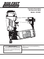
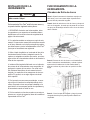
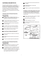
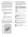
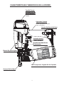
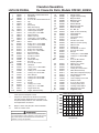
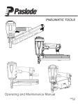
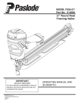
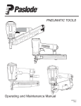
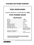
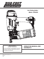
Coil Siding Nailer Model DF225C OPERATING MANUAL AND SCHEMATIC IMPORTANT! DO NOT DESTROY It is the customer’s responsibility to have all operators and service personnel read and understand this manual. PRINTED IN U.S.A. © 2009, Illinois Tool Works, Inc. 503026-1 08/09 1 INTRODUCTION The Duo-Fast® DF225C coil siding nailer is a quality-built tool designed for use in residential siding, fencing, decking, pallet & crating applications. This tool will deliver efficient, dependable performance when used according to the manufacturer’s guidelines. Please study this manual, including the safety instructions, to fully understand the operation of this tool. TOOL AND FASTENER SPECIFICATIONS ................................................................. 3 SAFETY INSTRUCTIONS ............................................................................................. 4 TOOL INSTALLATION AND OPERATION ................................................................ 5-6 AIR SYSTEMS ............................................................................................................. 7-8 FEATURES AND BENEFITS .......................................................................................... 9 EXPLODED VIEW AND SPARE PARTS LIST ....................................................... 10-11 MAINTENANCE ....................................................................................................... 12-13 TROUBLESHOOTING .................................................................................................. 14 WARRANTY .................................................................................................................. 15 ACCESSORIES ........................................................................................................... 16 2 TOOL AND FASTENER SPECIFICATIONS TOOL SPECIFICATIONS MODEL NO. DF225C (Part# 502950) HEIGHT 12 5/8” WIDTH 5 3/4” LENGTH 11" WEIGHT 4 lbs. 5 oz. OPERATING PRESSURE 80 to 120 psi (5.5 to 8.3 bar) MAGAZINE TYPE 0 Degree, Plastic Coil FASTENER SPECIFICATIONS NAIL LENGTH 1 1/4” - 2 1/2” SHANK DIAMETER .080 -.105” NAIL COATINGS Electro-Galvanized, Aluminum, Hot Dipped Galvanized, Stainless Steel TOOL AIR FITTINGS: This tool uses a 1/4” N.P.T. male plug. The fitting must be capable of discharging tool air pressure when disconnected from the air supply. OPERATING AIR PRESSURE: 80 to120 psi (5.5 to 8.3 bar). Select the operating air pressure within this range for best tool performance. DO NOT EXCEED THIS RECOMMENDED OPERATING PRESSURE. 3 SAFETY INSTRUCTIONS SAFETY FIRST These safety instructions provide information necessary for safe operation of Duo-Fast ® tools. DO NOT ATTEMPT TO OPERATE THE TOOL UNTIL YOU READ AND UNDERSTAND ALL SAFETY PRECAUTIONS AND MANUAL INSTRUCTIONS. DISCONNECT THE TOOL WHEN NOT IN USE Always disconnect the tool from the air line when it is not in use, when you leave the work area or when moving the tool to a new location. The tool must never be left unattended because people who are not familiar with the tool might handle it and injure themselves or others. WEAR EYE AND HEARING PROTECTION Always wear hearing and eye protection devices, that conform to ANSI Z87.1 requirements, when operating or working in the vicinity of a tool. As an employer you are responsible for enforcing the use of eye protection. Wear hard hats in environments that require their use. CARRY THE TOOL ONLY BY THE HANDLE Always carry the tool by the handle only. Never carry the tool by the air hose or with the trigger depressed since you could drive a fastener unintentionally and injure yourself or someone else. THE TOOL MUST BE USED ONLY FOR THE PURPOSE FOR WHICH IT WAS DESIGNED Do not throw the tool on the floor, strike the housing in any way or use the tool as a hammer to knock material into place. DO NOT WEAKEN THE TOOL HOUSING The tool housing is a pressure vessel and should never be weakened by having your company’s name, area of work or anything else stamped or engraved into its surface. NEVER ENGAGE IN HORSEPLAY WITH THE TOOL The tool is not a toy so do not use it like one. Never engage in horseplay with the tool or point it at yourself or any other person, even if you think it is not loaded. DISCONNECT THE TOOL WHEN PERFORMING REPAIRS AND CLEARING JAMS Never attempt to clear a jam or repair a tool unless you have disconnected the tool from the air line and removed all remaining fasteners from the tool. NEVER ASSUME THE TOOL IS EMPTY Check the magazine for fasteners that may be left in the tool. Even if you think the tool is empty or disconnected, never point it at anyone or yourself. Unseen fasteners could fire from the tool. ALWAYS USE THE PROPER FITTING FOR THE TOOL Only MALE pneumatic type air connectors should be fitted to the tool, so that high pressure air in the tool is vented to atmosphere as soon as the air line is disconnected. NEVER install FEMALE quick disconnect couplings on the tool. Female couplings will trap high pressure air in the tool when the air line is disconnected, leaving the tool charged and able to drive at least one fastener. NEVER CLAMP THE TRIGGER IN A LOCKED OR OPERATING POSITION The trigger of the tool must never be tampered with, disabled or clamped in a locked or operating position since this will cause the tool to drive a fastener any time the work contacting element depressed. DO NOT EXCEED THE MAXIMUM RECOMMENDED AIR PRESSURE Operate the tool only at the recommended air pressure. Do not exceed the maximum air pressure marked on the tool. Be sure the air pressure gauge is operating properly and check it at least twice a day. DO NOT LOAD FASTENERS WITH THE AIR LINE CONNECTED, OR WITH THE TOOL TRIGGER OR WORK CONTACTING ELEMENT DEPRESSED When loading fasteners into the tool be sure you disconnect the air line and that you do not depress the trigger or work contacting element. Never use any bottled air or gases such as oxygen to operate the tool since they could cause the tool to OPERATE THE TOOL ONLY ON A WORKPIECE The tool should be operated only when it is in contact with the workpiece. Even then you should be careful when fastening thin material or working near the edges and corners of the workpiece since the fasteners may drive through or away from the workpiece. explode. INSPECT TOOL FOR PROPER OPERATION Clean the tool at least daily and lubricate as required. Never operate a dirty or malfunctioning tool. USE ONLY DUO-FAST® RECOMMENDED PARTS AND FASTENERS Use only parts and fasteners specifically designed and recommended by Duo-Fast ® for use in the tool and for work to be done. Using unauthorized parts and fasteners or modifying the tool in any way creates dangerous situations. Replace all missing warning labels---refer to tool schematic for correct placement and part number. DO NOT DISABLE OR REMOVE THE WORK CONTACTING ELEMENT This tool is equipped with a safety mechanism, called a work contacting element, to help prevent accidental firing. Never tamper with, disable or remove the work contacting element. Do not use the tool unless the work contacting element is working properly. The tool could fire unexpectedly. WARNING Failure to follow any of the above instructions could result in severe personal injury to tool user and bystanders or cause damage to tool and property. 4 TOOL INSTALLATION TOOL OPERATION Loading of Nails Step No. 1- Grasp the nailer handle firmly with one hand and with the other hand depress the door latch. Swing the magazine and door open. Your Duo-Fast tool comes ready for immediate use and can be installed by following these steps: Step No. 2- Remove the retaining tape from the ® nail coil and place the nail coil in the magazine with the tips of the nails against the loading tray and about 4 inches of coil unwound. 1. SAFETY - All tool operators and their immediate supervisors must become familiar with the operator safety instructions before operating the tool. The instructions are on page 4 of this manual. 2. Included with each tool is a copy of the operation manual and schematic. Keep this publication for future reference. An ownership registration card is also included. This card must be completed and returned to Duo-Fast ® immediately to register your ownership. 3. The plastic cap in the air inlet of the tool must be removed before the male fitting is installed. The fitting must be a male pneumatic type that discharges the air from the tool when the air line is disconnected. Step No. 3- Slide the free strip of nails along the top of the feeder body assembly and feed the nails over the feed pawls until the first nail is in the nose raceway. 4. Install a filter/regulator/lubricator unit, with a gauge as close as practical to the tool, preferably within ten feet. Refer to the Air Systems section of this manual for air hose requirements and lengths. In general, no other special installation is required. 5. If the operator is working at a bench or table, it is usually best to run the air line underneath the bench. A small tray under the benchtop can hold the fastener supply and the tool when not in use. 6. If this tool does not work when it is first connect® ed, do not try to make repairs. Call your Duo-Fast representative immediately. Step No. 4- Close the magazine cover and then the gate making sure the gate is latched securely. 5 TOOL OPERATION continued Note: Follow the siding manufacturer’s instructions when installing the nails. Always use the nail size specified by the siding manufacturer and/or the local building codes. WARNING Use only fasteners that meet Duo-Fast® specifications. Use of fasteners that do not meet Duo-Fast specifications can result in damage to the tool or injury to the operator or bystanders. ® Successive (Bounce) Driving - (Orange Trigger) ■ Grasp the handle firmly. Squeeze the trigger and move the tool along the workpiece with a bouncing motion, depressing the work contacting element at the points where you want to insert a fastener. ■ Keep the trigger depressed and continue to bounce the work contacing element against the workpiece, positioning the tool above as carefully as possible. ■ When the desired number of fasteners have been driven, release the tool trigger to avoid unintentional fastener discharge. ■ Driving of Nails Precision Placement Driving - (Orange Trigger) ■ Grasp the tool handle firmly and hold the bottom of the work contacting element firmly against the workpiece until it is completely depressed. ■ Squeeze the trigger to drive the fastener. ■ Lift the tool from the workpiece. ■ Repeat the procedure for the next fastener. Sequential Operation - (Gray Trigger) The sequential operating kit prevents successive or “bounce” driving. Depress the work contacting element and hold it against the work surface before pulling the trigger. ■ After each fastener is driven, completely release the trigger and lift the tool from the work surface. ■ 6 AIR SYSTEMS • Air hoses are not longer than 150 feet. For air-powered tools to work their best, the air supply system must be properly installed and maintained regularly. A drawing in this section shows a properly installed air supply system. Handy checklists for installing and maintaining air supply systems follow. • The air system is lubricated regularly. • A regular maintenance program is followed. Indoor Air System Installation -Be certain that: Filter/Regulator/Lubricator Units Filter/regulator/lubricator units that can supply enough air and protection for Duo-Fast ® tools must meet the following specifications: • All pipes supplying air have a large enough inside diameter to ensure adequate air supply. • The main supply pipe slopes down, away from • Minimum 3/8 inch NPT port the compressor (1/16 inch per foot). size . • 50 micron or fine filters. • Air storage is provided along lengthy air lines. • Regulated pressure from zero to 120 psi. • Pipe line branch outlets are at the top of the main pipe line. • Lubricators designed for low or changing airflow. • Cutoff valves are provided at each branch pipe line throughout the system. • Water legs extend from the bottom of each branch line. • A refrigerant-type dryer is installed on the system. • Air hoses are kept as short as practical. • A regular maintenance program is followed. Outdoor Air System Installation -Be certain that: • A moisture trap and a filter/regulator/lubricator are installed at the compressor. • Air hoses and fittings are large enough so that air flow is not restricted. Minimum hose size is 3/8 inch ID with 1/2 inch ID hose used for any application over 25 feet. 7 AIR SYSTEMS - Continued Calculating Compressor Size Use the air consumption chart in the Tool Schematic for each tool when calculating the operating requirements for the tools. Duo-Fast ® tools are designed to operate efficiently between 80 and 120 psi and should never be operated at pressure greater than 120 psi. The air consumption chart will help you find the correct compressor size for your application that will quickly replenish tool air pressure. To use the chart you will need to know how many tools will be used and approximately how many fasteners will be driven each minute by each tool onthe line. Using the equation: Number of tools X average fasteners/minute/ tool X 1.2 (safety factor) X air consumption (scfm) @ pressure* (psi) = scfm required. We can use the following example: 10 tools X 30 fasteners/minute/tool X 1.2 X 0.051scfm* (@100psi) = 18.36 scfm. *This number is found in the Air Consumption Chart In this example, using the air consumption chart we find that a compressor providing at least 19 scfm of air is required. Because in compressors approximately 1 hp is required to produce 4 scfm, a compressor of at least 5 hp is required. Calculated Required Piping For example, given a 20 hp electric compressor supplying approximately 80 cfm of air at 120 psi and a main supply pipe length of 350 feet, we see by the table the minimum main pipe inside diameter required for this application is 1-1/4 inch. LENGTH OF RUN (FT.) VOLUME OF AIR (CFM) 50-200 30-60 1 1 1¼ 1½ 1½ 60-100 1 1¼ 1¼ 2 2 100-200 1¼ 1½ 2 2¼ 2½ 200-500 2 2½ 3 3½ 3½ 500-1000 2½ 3 3½ 4 4½ 290-500 500-1000 1000-2500 2500-5000 NOMINAL PIPE DIAMETER (IN.) Pneumatic System Maintenance - Be certain that: • Pneumatic fittings are tight and do not leak. and ensure that automatic draining systems are operating correctly. • Air lines are cleared to prevent freezing, especially in winter. • Lubricator operation is checked regularly and ensure it has an adequate supply of lubricant. (Part No. 403720) • Only regulated air is being used and that each regulator is operating properly. 8 DF225C FEATURES AND BENEFITS Adjustable Exhaust Cap Deflects air away from user. Comfort Grip Ergonomic design provides greater comfort. Metal Belt Hook Successive Trip Trigger (Orange) Tool-Less Depth of Drive Lightweight Design 4.5 Lbs. Clear View, High Capacity Magazine No-Mar Work Contact 9 PARTS LEGEND * ** 502996 502997 502969 502998 502970 503236 502971 502972 503021 502973 503218 502974 502975 503219 502976 502977 502220 503246 502978 503221 502979 502979 503223 503224 502980 502981 502982 503225 502983 503227 503214 503228 503229 503215 503230 503231 503232 503216 503233 503234 503217 502984 1 1 1 4 1 1 1 1 1 1 2 1 1 1 1 1 1 1 1 1 3 1 1 1 2 1 1 5 1 1 1 1 1 1 1 1 1 1 2 1 1 1 BHCS M5 x 10mm-P30 Precoat Flat Washer Air Deflector S.H.C.S. M5 x 20mm-P30 Precoat Cap Collar Piston Stop Main Valve Spring O-Ring 35.5 x 2mm NBR Outer Poppet Assembly O-Ring 49.5 x 2mm NBR Sleeve Retainer Gasket, Top Cap O-Ring 38.7 x 3.5mm NBR Driver Blade/Piston Assembly Sleeve O-Ring 45.7 x 2.6mm NBR O-Ring 47.3 x 2.6mm NBR Sleeve Bulkhead Seal O-Ring 68 x 3mm NBR O-Ring 1.9 x 1.9mm NBR Housing/Handle Roll Pin 3 x 20mm Roll Pin 3 x 30mm Pin, Trigger Gasket, End Cap End Cap S.H.C.S. M5 x 16mm Belt Hook O-Ring 15.6 x 1.8mm NBR Trigger Valve O-Ring 17.5 x 1.5mm NBR O-Ring 5.8 x 1.9mm NBR Valve Plunger O-Ring 6.8 x 1.9mm NBR O-Ring 8.8 x 1.9mm NBR Spring Plunger O-Ring 2.5 x 1.4mm O-Ring 21 x 1.5mm NBR Trigger Valve Cap Trigger Valve Assembly Apply Loctite® 242 (Blue) Part No. 093500 ➔ Denotes New Change 502985 502986 502987 502988 502042 502989 502990 502991 502992 502993 502994 502995 503200 503201 503202 502999 503203 503204 503237 503238 503007 503239 502340 503206 503241 1 1 1 1 1 3 1 1 1 1 1 1 1 1 1 1 1 1 2 1 1 1 1 1 4 68 69 70 71 72 73 74 75 76 77 78 79 80 81 ** 82 503207 503208 503209 503242 503210 503211 503212 503243 503244 503213 503245 503247 503248 503249 503250 2 1 1 1 1 1 1 1 1 1 1 1 1 1 1 WARNING All parts must be periodically inspected and replaced if worn or broken. Failure to do this can affect the tool’s operation and present a safety hazard. .090 .080 .070 .060 . .066 .050 .040 .030 60 70 80 90 100 110 120 AIR PRESSURE-PSIG 10 502950 Spring, Trigger Trigger Lever Assembly Magazine Base Magazine Cover Lock Nut, M5 Rubber Washer Magazine Hinge Pin WCE Assembly No --Mar Tip Depth of Drive Assembly Check Pawl Pin Check Pawl Check Pawl Spring Nail Door Nail Door Pin Guide Nail Door Torsion Spring Nail Door Pin Feed Cover Flat Washer 4 x 10mm S.H.C.S. M4 x 5mm Bumper O-Ring 47.4 x 1.8mm NBR O-Ring 3.7 x 1.8mm NBR Nose S.H.C.S. M6 x 20mm W/Spring Washer Roll Pin, 2.5 x 12mm Nail Feed Pawl Piston, Nail Feed O-Ring 18 x 2.5mm Viton Nail Feed Piston Stop Nail Feed Compression Spring Nail Feed Spring Collar C Ring, 24mm Torsion Spring, Door Latch Nail Door Latch S.H.C.S. M4 x 10mm Housing Label, LEFT Housing Label, RIGHT Magazine Door Label Magazine Label AIR CONSUMPTION CHART Denotes Normal Wear Items Make sure Warning Label (Part No.503250) is properly affixed. Replace if necessary. Label available at no charge through the Service Department. ▲ DF225C 43 44A 45 46 *47 48 49 50A *51 52A 53 54 55 56 57 58 59 60 61 62 *63 64 65 66 ▲67 AIR CONSUMPTION-CFM FASTENER 1 2 3 ▲ 4 5 6 7 8 *9 10A *11 12 13 *14 *15 A 16 *17 *18 19 *20 *21 22 23 24 25 26 27 ▲ 28 29 * 30 31 *32 33 34 *35 * 36 37 *38 *39 *40 41 42A Coil Siding Nailer DF225C 502950 88 28 1 27 2 29 26 3 14 88 4 21 15A 5 30 31 32 33 34 35 23 6 7 24 89 16 25 8 36 37 38 39 40 41 22 88 9 10A 44A 18 11 42A 43 17 28 47 **82 19 52A 12 45 20 13 48 63 49 50A 53 64 65 60 54 75 68 48 55 21 56 57 51 58 59 36 61 69 70 76 62 71 77 72 61 73 74 48 78 46 67 150 66 81 Torque Values IN/LBS MAINTENANCE Duo-Fast ® tools are built for ease of maintenance. A few simple details will assure trouble-free operation and long tool life. Anyone who uses or maintains the tool must read the safety and maintenance instructions. Study the schematic drawing before starting any repairs on the tool. Testing the Tool After Servicing Air-operated tools must be inspected periodically, and worn or broken parts must be replaced to keep the tool operating safely and efficiently. Also the items on the maintenance chart must be checked often. ❑ Ensure that all hardware is tight. After replacing any part or parts, it is important to check the tool for proper operation. This ensures that the tool was put together correctly, is safe to use, and will perform the job properly. ❑ Ensure that the work contacting element is installed correctly in relation to the trigger, and that both parts move freely. Cold Weather Care ❑ Ensure that the magazine is properly attached. When temperatures are below freezing, tools should be kept warm by any convenient, safe method. If this is not possible, the following procedure should be used to warm up the tools. ❑ Ensure that the required safety information on the tool is legible. ❑ Use only Duo-Fast ® approved fasteners in the tool, and ❑ Reduce the regulated air pressure to 30 psi. ensure that they are correct for the application. ❑ Remove all fasteners from the tool. ❑ Ensure that a male air fitting is securely connected to the tool. ❑ Connect an air line and blank fire the tool. The reduced air pressure will be enough to free-fire the tool. Slow speed operation tends to warm up the moving parts. Slowing up the piston helps the bumper and the O-rings to become springy. ❑ Once the tool is warmed up, readjust the regulator to the proper working pressure and reload the tool. ❑ Tool operators working outdoors or in unheated areas in extremely cold temperatures should also: Use pneumatic oil with antifreeze in the lubricator, Part No. 219090 (8oz.) Cleaning the air-operated tools with solvents removes the thin coating of grease applied to the cylinder wall and O-rings at the factory. To replace this coating of grease, use Chemplex® grease (Part No. 403734). ❑ Open the drain on the air compressor tank to drain any moisture at least daily in extremely cold or humid weather. A few ounces of antifreeze in the tank will keep the air free of frost. 12 ❑ Test the tool by driving fasteners into a workpiece identical to the tool's application. ❑ Check the tool for air leaks during testing and for the proper sequence of operation. ❑ Ensure that all fasteners are driven to the same depth and that the crown of the fastener is flush with the workpiece. Tool Lubrication It is most important that the tool be properly lubricated by keeping the air line lubricator filled and correctly adjusted. Without proper lubrication the tool will not work properly and parts will wear prematurely. Use the proper lubricant in the air line lubricator. The lubricator should be of low air flow or changing air flow type, and should be kept filled to the correct level. Use only Duo-Fast ® recommended lubricants. Substitutes may harm the rubber compounds in the tools O-rings and other rubber parts. Part No. 403720 is a pneumatic lubricating oil is specially made for pneumatic applications. If a filter/regulator/lubricator is not installed on the air system, air operated tools should be lubricated at least once a day with 6 to 20 drops of oil, depending on the work environment, directly through the male fitting in the tool housing. Most minor problems can be resolved quickly and easily using the maintenance table that follows. If problems persist, contact your Duo-Fast ® dealer for assistance. MAINTENANCE - Continued CAUTION Disconnect the tool when performing repairs or clearing jams. MAINTENANCE TABLE ACTION WHY HOW Drain air line filter(daily). Prevent accumulation of moisture and dirt. Open manual petcock (most air supply systems have such a valve). Keep lubricator filled. Keep tool lubricated. Fill with pneumatic tool lubricant. Part No. 403720. Clean filter element-then blow air through filter in direction opposite to normal flow. Prevent clogging of filter with dirt. Wash with soap and water or follow manufacturers instructions. Check that all screws on tool are tight. Prevent air leakage and promote efficient operation. Check screws daily. Keep work contacting element working properly. Promote operator safety and efficient tool operation. Blow clean daily. Keep magazine and feeder mechanism clean. Prevent jamming of fasteners. Blow clean daily. Lubricate "O" rings that are replaced. Assure long life and proper operation of tool. Use Chemplex ® grease, Part No. 403734. Use only Duo-Fast ® replacement Keep tool operating efficiently parts. and maintain Duo-Fast ® tool warranty. Order any repacement parts ® needed from Duo-Fast Dealer. Check the driver blade regularly Ensure proper operation of the and replace when worn. tool. Remove piston and driver assembly from tool and compare with new driver blade. Replace when worn. 13 OPERATOR TROUBLESHOOTING CAUTION Disconnect the tool when performing repairs or clearing jams. PROBLEM CORRECTIVE ACTION Fasteners will not drive completely into wood. Increase air pressure (do not exceed 120 psi). Fasteners penetrate properly during normal operation, but won't drive fully at faster speeds. Increase air flow to tool -- use larger air lines (3/8 inch ID minimum). Fasteners drive too deeply into wood. Reduce air pressure. Make sure correct fasteners are being used. Use fasteners that meet Duo-Fast ® specifications only. Tools skips during operation - no fasteners are driven from time to time. Inspect check and feed claw for wear and proper operation. Clean as needed to remove debris. Increase air flow to tool -- use larger air lines (3/8 ID minimum). Check magazine for proper fasteners. Fasteners should slide freely with no follower pressure. Tool operates, but no fasteners are driven. Increase air pressure (do not exceed 120psi). Tighten capscrews. Air leaks at cap when tool is connected to air. 14 TOOL WARRANTY An Illinois Tool Works Company 955 National Parkway Schaumburg, Illinois 60173-5172 TOOL WARRANTY AND LIMITATIONS Duo-Fast® warrants that newly purchased power fastening tools, parts and accessories will be free from defects in material and workmanship for the period shown below, after the date of delivery to the original user. WARRANTY STATEMENT This warranty is limited to tools sold and service requested in the United States. To obtain information on warranty service in the United States, refer to the Service Center listing that was provided with your tool. 90-DAY LIMITED WARRANTY Duo-Fast's sole liability hereunder will be to replace any part or accessory which proves to be defective within the specific time period. Any replacement part or accessory provided in accordance with this warranty will carry a warranty for the balance of the period of warranty applicable to the part it replaces. This warranty does not apply to part replacement required due to normal wear. A 90-day warranty will apply to all parts, except those which are specifically covered by an extended warranty. EXTENDED LIMITED WARRANTY FOR ON SITE CONSTRUCTION APPLICATIONS A one year warranty will apply to all housing and cap assembly castings. A six month warranty will apply to all magazine parts. NORMAL WEARING PARTS The following parts are considered normal wearing parts and are not under warranty. • Bumper • Driver Blades • ”O” Rings • Piston Rings This warranty is void as to any tool which has been subjected to misuse, abuse, accidental or intentional damage, use with fasteners, fuel, batteries, or battery chargers not meeting DuoFast® specification, size, or quality, improperly maintained, repaired with other than genuine Duo-Fast® replacement parts, damaged in transit or handling, or which, in Duo-Fast's opinion, has been altered or repaired in a way that affects or detracts from the performance of the tool. ® DUO-FAST MAKES NO WARRANTY,EXPRESSED OR IMPLIED, RELATING TO MERCHANTABILITY, FITNESS, OR OTHERWISE, EXCEPT AS STATED ABOVE, and DUOFAST's liability AS STATED ABOVE AND AS ASSUMED ABOVE is in lieu of all other warranties arising out of, or in connection with, the use and performance of the tool, except to the extent other wise provided by applicable law. ® DUO-FAST SHALL IN NO EVENT BE LIABLE FOR ANY DIRECT, INDIRECT, OR CONSEQUENTIAL DAMAGES, INCLUDING, BUT NOT LIMITED TO, DAMAGES WHICH MAY ARISE FROM LOSS OF ANTICIPATED PROFITS OR PRODUCTION, SPOILAGE OF MATERIALS, INCREASED COST OF OPERATION, OR OTHERWISE. 15 ACCESSORIES Lubricants and Loctite Loctite® 242 (Blue) Lubricating Oil 16 oz. Lubricaing Oil with Antifreeze 8 oz. Chemplex ® 710 Lubricant 1lb. Lubricant 5 gram tube ® Part No. Part No. Part No. Part No. Part No. 093500 403720 219090 403734 219188 Degreaser Cleaner Ideal cleaner for all Duo-Fast tools. ® Safety Glasses Clear Part No. 902330 Part No. 401382 Tool Case Heavy duty nylon carrying case with 16 pockets. An Illinois Tool Works Company 955 National Parkway Schaumburg, Illinois 60173-5172 Duo-Fast® is a registered trademarks of ITW. All other trademarks are property of their respective owners. Part No. 219246 Clavadora Neumática De Clavos En Rollo Modelo DF225C Manual de Funcionamiento y Esquema ¡IMPORTANTE! NO DESTRUYE ESTE MANUAL El cliente tiene la responsibilidad de que todo el personal de operaciones y servicio lea y entienda este manual. 17 INTRODUCCIÓN La Duo-Fast® DF225C clavadora neumática es una herramienta de construcción de calidad, diseñado para la construcción residencial en el revestimiento, vallas, cercado, patios, paletas y aplicaciones de paqueteria. Esta herramienta entrega eficiente y seguro cuando se utiliza de acuerdo con las operación instrucciones del fabricante. Por favor estudié este manual, incluyendo las instrucciones de seguridad, para comprender el funcionamiento de esta herramienta. CONTENIDO SPECIFICACIONES DEL LA HERRAMINETA Y SUS SUJETADORES.............................3 INSTRUCCIONES DE SEGURIDAD................................................................................... 4 INSTALACION Y OPERACION DE LA HERRAMINETA..................................................5-6 SISTEMAS DE AIRES......................................................................................................7-8 BENEFICIOS DE LA HERRAMIENTA................................................................................ 9 ESQUEMA CON LISTA DE PIEZAS DE REEMPLAZOS.............................................10-11 MANTENIMIENTO.........................................................................................................12-13 DETECCION Y CORRECION DE FALLAS........................................................................14 GARANTIA.........................................................................................................................15 ACESORIOS.......................................................................................................................16 18 2 ESPECIFICACIONES DE LA HERRAMIENTA Y LOS SUJETADORES ESPECIFICACIONES DE LA HERRAMIENTA NO. de MODELO DF225C (Pieza# 502950) ALTURA 12 5/8” ANCHO 5 3/4" LONGITUD 11" PESO 4 lbs. 5 oz. PRESIÓN de OPERACIÓN 80 hasta 120 psi (5.5 hasta 8.3 bar) TIPO de CARGADOR 0 Grados, en Rollo, de plástico ESPECIFICACIONES de los SUJETADORES LONGITUD DEL CLAVO 1 1/4" - 2 1/2” DIAMETRO DEL TALLO .080 -.105 ACABADOS DEL CLAVO Electro-galvanizado, aluminio, galvanizado a fuego y acero inoxidable. ACOPLAMIENTO DE AIRE: Esta herramienta utiliza un tapón macho de 1/4" N.P.T. El acoplamiento debe ser capaz de descargar la presión de aire en la herramienta cuando sea desconectada del suministro de aire. OPERACION de PRESIÓN de AIRE: 80 hasta120 psi (5.5 hasta 8.3 bar). Seleccione una presión de aire dentro de esta gama para obtener el mejor rendimiento. NO EXCEDA LA PRESIÓN DE AIRE RECOMENDADA. 19 3 INSTRUCCIONES DE SEGURIDAD LA SEGURIDAD ESTA PRIMERO DESCONECTE LA HERRAMIENTA CUANDO NO LA ESTE USANDO Estas instrucciones proporcionan la información necesatia para el funcionamiento sin peligrode las herramientas Duo-Fast®. NO trate de usar su herramienta hasta que no haya léido y entendido todas las precauciones de seguridad y las instrucciones de este manual. Siempre desconecte la herramienta de la línea de aire comprimdo cuando no la esté usando o al dejar su lugar de trabajo. Nunca la descuide, porque cualquier persona que no esté familiarizada con ella podría lastimarse o lastimar otros. PROTEJASE LOS OJOS Y LOS OIDOS Use siempre el equipo adecuado para protegerse los ojos y los oídos que sea conforme con ANSI Z87, meintras usa una herramienta o trabaja cerca de una herramienta en uso. Como empleador usted es responsable de imponer el usp del la porteccion de ojo. Lleve sombreros duros en los ambientes que requieren su uso. TOME LA HERRAMIENTA SOLAMENTE POR EL MANGO Siempre tome la herramienta sólo por el mango. Nunca la tome por la manguera o con el gatillo oprimido, porque se podría disparar un sujetador y herirlo o herir a otra persona. NO ALTERE EL ARMAZON DE LA HERRAMIENTA El armazón de la herramienta es un recipiente a presión y nunca se debe grabar en su superficie el nombre de su compañia, el del área de trabajo, ni ningún otro detalle. USE SU HERRAMIENTA SOLAMENTE PARA EL PROPOSITO CON QUE FUE DISEÑADA No arroje la herramienta al suelo; no golpee el armazón ni la use como un martillo. DESCONECTE LA HERRAMIENTA PARA HACER REPARACIONES O ELIMINAR OBSTRUCCIONES Nunca trate de eliminar obstrucciones o reparar una herramienta sin haberla desconectado de la línea de aire compromido y quitado todos los sujetadores. NUNCA USE LA HERRAMIENTA PARA JUGUETEAR Esta herramienta no es un juguete; por lo tanto no la trate como tal. Nunca juguetee con ella, ni se apunte a usted mismo ni a otra persona, aun cuando crea que no está cargada. USE SIEMPRE LOS ADAPTADORES APROPIADOS PARA SU HERRAMIENTA NUNCA ASUMAQUE LA HERRAMIENTA ESTA VACIA Se debe conectar a la herramienta solamente conectores neumáticos MACHOS, para permitir que el aire de alta presíon salga tan pronto como se desconecte la línea de aire comprimido. Verfique que ho haya sujetadores en elcargador. Aun cuando crea que está vacía o desconectada, nunca se apunte ni apunte a otra persona con la herramienta, porque podría dispararse un sujetador que no esté a la vista. NUNCA coloque enlaces HEMBRAS de desconexíon rápida en la herramienta, porque atrapan el aire a alta presíon al desconectar la línea de aire comprimido, dejándola cargada y lista para disparar por lo menos un sujetador. NUNCA SUJETE EL GATILLO EN LA POSICION DE CIERRE O DE FUNCIONAMIENTO Nunca se debe manipular indebidamente o dejar inoperante el gatillo, o sujetarlo en la posición de cierre o defuncionamiento, porque se podría disparar un sujetador al oprimirse el elemento de contacto. NO EXCEDA LA PRESION NEUMATICA MAXIMA RECOMENDADA La herramienta debe funcionar sólo con la presíon neumática recomendada. No exceda la presíon neumática máxima marcada en la herramienta. Verifique por lo menos dos veces al día que el calibre de la presíon neumática funcione correctamente. NO CARGUE SUJETADORES CUANDO LA LINEA DE AIRE COMPRIMIDO ESTE CONECTADA, O CUANDO EL GATILLO O EL ELEMENTO DE CONTACTO ESTE OPRIMIDO. Nuna use aire o gases envasado, como el oxígeno, para hacer funcionar la herramienta porque podrían hacer que explotara. Antes de cargar sujetadores en la herramienta, verifique que la línea de aire comprimido esté desconectada y que ni el gatillo ni el elemento de contacto estén oprimidos. INSPECCIONE LA HERRAMIENTA PARA LA OPERACION APROPIADA Limpie diariamente la herramienta y lubríquela como se recomienda. Nunca trate de hacer funcionar una herramienta sucia o defectuosa. USE LA HERRAMIENTA SOLAMENTE SOBRE UN MATERIAL DE TRABAJO La herramienta debe funcionar sólo cuando esté en contacto con el material de trabajo. Debe tener mucho cuidado cuando el material sea delagado o trabaje cerca de las aristas del mismo, porque los sujetadores podrían atravesar o salirse del material. USE SOLAMENTE PIEZAS Y SUJETADORES RECOMENDADOS POR DUO-FAST ® Use sólo piezas y sujetadores específicamente diseñados y recomendados por Duo-Fast® para usar con esa herramienta y para la tarea requerida. Si se usan piezas o sujetadores no autorizados o se modifica de alguna forma la herramienta, se pueden crear situaciones peligrosas. Vuelva a colocar todas las etiquetas de precaucíon que flaten. Consulte el diagrama de la herramienta sobre el número de cada parte y su ubligación correcta. NO DEJE INOPERANTE NI QUITE EL ELEMENTO DE CONTACTO Esta herramienta está equipada con un mecanismo de seguridad, llamado elemento de contacto, para prevenir cualquier disparo accidental. Nunca manipule indebidamente, deje inoperante, ni quite el elemento de contacto. No use la herramienta a menos que dicho elemento funcione correctamente, porque podría producirse un disparo imprevisto. PELIGRO La falta de observación de cualquiera de estas instrucciones puede ser causa de graves lesiones personales, tanto al operador de la herramienta comoa quienes estén cerca de ella o de daños materiales o a la herramienta. 20 4 INSTALACION DE LA HERRAMIENTA FUNCIONAMIENTO DE LA HERRAMIENTA Clavadora de Rollo de clavos PELIGRO Paso 1: Sujete firmemente la clavadora manejar con una mano y con la otra mano bajar el pestillo de la puerta. Abra la puerta del cargador. La presión de aire en la herramienta nunca debe exceder 120 psi. Paso 2: Quite el retén de un rollo de clavos y coloque el rollo en el cargador, de modo que la punta de los clavos se apoye en la bandeja, teniendo unos 10 cm de clavos desen rollados. Su herramienta Duo-Fast está lista para usarse y se puede instalar siguiendo estos pasos: ® 1. SEGURIDAD: Antes de usar la herramienta, todos los operadores y sus supervisores inmediatos deben familiarizarse con las instrucciones de seguridad de la página 4 de este manual. 2. Con cada herramienta se entrega una copia de este manual. Conserve este manual para cualquiera consulta en el futuro. Además, se incluye una targeta de registro, que debe llenarse y enviar inmediatamente a Duo-Fast® para que su herramienta sea registrada. 3. Quite el tapón de plástico en la entrada del aire de la herrmienta antes de instalar el adaptador macho. Se requiere un adaptador neumático tipo macho, que descargue el aire de la herramienta cuando se desconecte la línea de aire conpresión. 4. Instale un filtro/regulador/lubricador con un indicador,. tan cercano al de la herramienta como sea posible, de preferencia a menos de tres metros. Con sulte le sección Sistemas Neumáticos de este manual sobre la longitud y los requisitos de las mangueras de aire conpresión. En general, no se exige ninguna otra instalación especial. Paso 3: Presente el rollo de clavos con la banda libre sobre el mecanismo transbordador y oriente el primer apertura de la banda entre la uña transbordador y guia para colocar el primer clavo en posición de descargo. 5. Si el operador usa una mesa para trabajar. se aconseja colocar la línea de aire comprimido debajo de la misma. Se puede colocar una pequeña bandeja en la parte inferior de la mesa para quardar los sujetadores y la herramienta cuando no están un uso. 6. Si la herramienta no funciona cuando se conecta por primera vez, no trate de repararla; llame de inmediato al representate de Duo-Fast.® Paso 4: Cierre la tapa del cargador y luego la puerta asegurándose de que la puerta quede trabada con sequridad. 5 FUNCIONAMIENTO DE LA HERRAMIENTA (Continuación) NOTA: Siga las instrucciones del fabricante de conectores metálicos cuando instale los clavos. Siempre use el tamaño de clavo especificado por el fabricante de conectores metálicos y/o los códigos de edificación locales. Impulsos sucesivos (de robote) (Gatillo Naranjado) Tome la herramienta firmemente por el mango. Apriete el gatillo y mueva la herramienta a lo largo del material de trabajo con un movimiento de robote, oprimiendo el elemento de contacto en los lugares donde quiera colocar un sujetador. ADVERTENCIA Solo use clavos que reunan las especificaciones de Duo-Fast.® El uso de clavos que no reunan las especificaciones de Duo-Fast® puede resultar en daños a la herramienta o causar lesiones personales al operador o a quienes estén cerca de ella. No mezcla diferentes tamaños de clavos dentro del cargador a la misma ves. Quite todos los clavos antes de cambiar a clavos de otro tamaño. Manteniendo apretado el gatillo, continúe haciendo rebotar el elemento de contacto contra el material de trabajo, colocando cuidadosamente la herramienta, como se indica más arriba. Una vez que haya colocado todos los sujetadores necesarios, deje de oprimir el gatillo para evitar que salgan más. PELIGRO Impulsó de Clavos No sujete ni sostenga el gatillo con ninguna otra cosa que no sea la mano. Colocación precisa (Naranjado) Tome firmemente la herramienta por el mango y sosténgala de modo que la base del elemento de contacto quede bienapoyada en el material de trabajo. Funcionamiento en secuencia (Gatillo Gris) Con el gatillo gris elfuncionamiento en secuencia evita los impulsos sucesivos o “de rebote” Apriete el gatillo para disparar el sujetador. Oprima el elemento de contacto y manténgalo apoyado contra el material de trabajo antes de apretar el gatillo. Separe la herramienta del material de trabajo. Repita el mismo procedimiento con el próximo sujetador. Después de haber impulsado cada clavo, suetar completamente el gatillo y levante la herramienta del material de trabajo. 6 SISTEMAS NEUMATICOS SISTEMAS NEUMÁTICOS El sistema neumático debe estar correctamente instalado y recibir mantenimiento periódicamente para que todas las herramientas de potencia neumática funcionen bien. El diagrama de más abajo muestra un sistema neumático correctamente instalado. A continuación se detallan las revisiones necesarias para la instalación y el mantenimiento de los sistemas neumáticos. La línea principal tenga una inclinación de (1/16 de pulgada por pie) a partir del compressor. ■ Existen almacenamientos de aire a lo largo de las líneas muy largas. ■ Las salidas de aire en las líneas secundarias estén en la parte superior de la línea principal. ■ Existen válvulas de cierre en cada una de las líneas secundarias de todo el sistema. ■ Las columnas de agua se extiendan desde el extremo inferior de cada línea secundaria. ■ Se haya instalado en el sistema un secador tipo refrigerante. ■ Las mangueras de aire sean tan cortas como sea posible. ■ Se siga un programa regular de mantenimiento. Instalación de Un Sistema Neumático para Exteriores - Asegure Que: ■ Se hayan instalado en el compresor un colector de humedad y un filtro/regulador/lubricador. ■ Las mangueras de aire y los adaptadores tengan la longitud suficiente para que el aire circule sin problemas. El diámetro mínimo de una manguera de aire es de 3/8 de pulgada y de 1/2 pulgada para cualquier aplicación de más de 7.60 m. ■ El sistema neumático sea lubricado periódicamente. ■ Se siga un programa regular de mantenimiento. Las unidades de filtro/regulador/lubricador capaces de proporcionarDuo-Fast aire y protección suficientes a las herramientas Duo-Fast ® deben tener las siguientes características: El diámetro interior de todas las líneas que suministran aire sea bastante grande como para garantizar un suministro de aire adecuado. ■ Las mangueras de aire no midan más de 45.70 m de longitud. Unidades de Filtro/Regulador/Lubricador Instalación de Un Sistema Neumático para Interiores - Asegure Que: ■ ■ 23 7 ■ Tamaño mínimo del orificio a presión y tempera tura normales de 3/8 de pulgada ■ Filtros de 50 micrones o más finos ■ Presión regulada de 0 a 120 psi ■ Lubricadores diseñados para corriente de aire baja o variable SISTEMAS NEUMATICOS (continuación) Cómo Calcular el Tamaño del Compresor Duo-Fast® Use la tabla de consumo de aire en el esquema de cada herramienta para calcular los requisitos de funcionamiento de las herramientas. Las herramientas Paslode han sido diseñadas para funcionar eficientemente entre 80 y 120 psi, y nunca se deben usar a presiones superiores a 120 psi. La tabla de consumo de aire le permitirá encontrar el tamaño correcto del Duo-Fast® compresor para reponer rápidamente la presión del aire en su herramienta. Cómo Calcular la Tubería Necesaria Por ejemplo, si un compresor eléctrico de 20 hp proporciona aproximadamente 80 pies³/min. de aire a 120 psi y la longitud de la línea principal es de 106.70 m, la tabla indica que el diámetro interior de la línea principal necesario para esta aplicación debe ser de 1-1/4 pulgadas como mínimo. Para usar la tabla necesita saber cuántas herramientas se usarán y aproximadamente cuántos sujetadores aplicará, por minuto, cada herramienta de la línea. Use esta ecuación: Número de herramientas X promedio de sujetadores/minuto/herramienta X 1.2 (factor de seguridad) X consumo de aire (pies³/min./ estándar) @ presión* (psi) = pies³/min./ estándar requeridos Importante: Presión de Aire (80-100 psi) Mantenimiento del Sistema Neumático - Asegure Que: Por ejemplo: 10 herramientas X 30 sujetadores/minuto/ herramienta X 1.2 X 0.051 pies³/min./ estándar* (@ 100 psi) = 18.36 pies³/min./ estándar. ■ Los adaptadores neumáticos estén apretados y no haya pérdidas. ■ Las columnas de agua, o los filtros y las líneas de aire se drenen diariamente, y que los sistemas de drenaje automáticos funcionen correctamente. ■ Las líneas de aire estén limpias para evitar que se congelen, especialmente en invierno. ■ El funcionamineto del lubricador se examine periódicamente y que el suministro ). de lubricante sea adecuado (Pieza N° 403720). ■ Se limpie el filtro cada seis meses. ■ Sólo se use aire regulado y que cada regulador funcione correctamente. ). * Esta cifra aparece en la tabla de Consumo de Aire. Usando la tabla de consumo de aire, este ejemplo demuestra que se necesita un compresor que proporcione 19 pies³/min./estándar de aire, por lo menos. Como en compresores se necesita aproximadamente 1 hp para proporcionar 4 pies³/min./estándar, se requiere, por lo menos, un compresor de 5 hp. 24 8 CARACTERÍSTICAS Y BENEFICIOS DE LA DF225C Tapa De Escape Ajustable Sin Uso De Herramientas Desvia el aire del usuario. Agarradera Comoda Diseño ergonómico promueve mayor comodidad. Gancho De Cinturón De Metal Activación Sucesiva (Gatillo Naranjo) Ajuste De Profundidad Sin Uso De Herramientas Diseño De Peso Ligero 4.5 Lbs. Vista Transparente, Cargador De Alta Capcidad Contacto De No-Marzo 25 9 LISTA DE PIEZAS, 1 2 3 ▲ 4 5 6 7 8 *9 10A *11 12 13 *14 *15 A 16 *17 *18 19 *20 *21 22 23 24 25 26 27 ▲ 28 29 * 30 31 *32 33 34 *35 * 36 37 *38 *39 *40 41 42A ▲ ➔ 1 1 1 4 1 1 1 1 1 1 2 1 1 1 1 1 1 1 1 1 3 1 1 1 2 1 1 5 1 1 1 1 1 1 1 1 1 1 2 1 1 1 BHCS M5 x 10mm-P30 Precoat Flat Washer Air Deflector S.H.C.S. M5 x 20mm-P30 Precoat Cap Collar Piston Stop Main Valve Spring O-Ring 35.5 x 2mm NBR Outer Poppet Assembly O-Ring 49.5 x 2mm NBR Sleeve Retainer Gasket, Top Cap O-Ring 38.7 x 3.5mm NBR Driver Blade/Piston Assembly Sleeve O-Ring 45.7 x 2.6mm NBR O-Ring 47.3 x 2.6mm NBR Sleeve Bulkhead Seal O-Ring 68 x 3mm NBR O-Ring 1.9 x 1.9mm NBR Housing/Handle Roll Pin 3 x 20mm Roll Pin 3 x 30mm Pin, Trigger Gasket, End Cap End Cap S.H.C.S. M5 x 16mm Belt Hook O-Ring 15.6 x 1.8mm NBR Trigger Valve O-Ring 17.5 x 1.5mm NBR O-Ring 5.8 x 1.9mm NBR Valve Plunger O-Ring 6.8 x 1.9mm NBR O-Ring 8.8 x 1.9mm NBR Spring Plunger O-Ring 2.5 x 1.4mm O-Ring 21 x 1.5mm NBR Trigger Valve Cap Trigger Valve Assembly Indica piezas de desgaste normal. Asegure que la Etiqueta de Advertencia (503250) este bien pegada. Reemplaze si es necesario. La etiqueta esta disponible sin costo adicional a traves del Departamento de Servicio. 43 44A 45 46 *47 48 49 50A *51 52A 53 54 55 56 57 58 59 60 61 62 *63 64 65 66 ▲67 502985 502986 502987 502988 502042 502989 502990 502991 502992 502993 502994 502995 503200 503201 503202 502999 503203 503204 503237 503238 503007 503239 502340 503206 503241 1 1 1 1 1 3 1 1 1 1 1 1 1 1 1 1 1 1 2 1 1 1 1 1 4 68 69 70 71 72 73 74 75 76 77 78 79 80 81 ** 82 503207 503208 503209 503242 503210 503211 503212 503243 503244 503213 503245 503247 503248 503249 503250 2 1 1 1 1 1 1 1 1 1 1 1 1 1 1 CONSUMO DE AIRE -CFM SUJETADOR * ** 502996 502997 502969 502998 502970 503236 502971 502972 503021 502973 503218 502974 502975 503219 502976 502977 502220 503246 502978 503221 502979 502979 503223 503224 502980 502981 502982 503225 502983 503227 503214 503228 503229 503215 503230 503231 503232 503216 503233 503234 503217 502984 Clavadora Neumática De Clavos En Rollo, Modelo DF225C, 502950 Aplique Loctite® 242 (Azul) No. de Pieza 093500 Indica un cambio nuevo . ADVERTENCIA Todas las piezas deben ser inspeccionadas periódicamente y ser reemplazadas si estan gastadas o rotas. Falta de hacer esto puede afectar el funcionamiento de la herramienta y presentar un riesgo de seguridad. .090 .080 .070 .060 Spring, Trigger Trigger Lever Assembly Magazine Base Magazine Cover Lock Nut, M5 Rubber Washer Magazine Hinge Pin WCE Assembly No --Mar Tip Depth of Drive Assembly Check Pawl Pin Check Pawl Check Pawl Spring Nail Door Nail Door Pin Guide Nail Door Torsion Spring Nail Door Pin Feed Cover Flat Washer 4 x 10mm S.H.C.S. M4 x 5mm Bumper O-Ring 47.4 x 1.8mm NBR O-Ring 3.7 x 1.8mm NBR Nose S.H.C.S. M6 x 20mm W/Spring Washer Roll Pin, 2.5 x 12mm Nail Feed Pawl Piston, Nail Feed O-Ring 18 x 2.5mm Viton Nail Feed Piston Stop Nail Feed Compression Spring Nail Feed Spring Collar C Ring, 24mm Torsion Spring, Door Latch Nail Door Latch S.H.C.S. M4 x 10mm Housing Label, LEFT Housing Label, RIGHT Magazine Door Label Magazine Label TABLA DE CONSUMO DE AIRE . .066 .050 .040 .030 60 70 80 90 100 110 120 PRESIÓN DE AIRE 10 DF225C 502950 88 28 1 27 2 29 26 3 14 88 4 21 15A 5 30 31 32 33 34 35 23 6 7 24 89 16 25 8 36 37 38 39 40 41 22 88 9 10A 44A 18 11 42A 43 17 28 47 **82 19 52A 12 45 20 13 48 63 49 50A 53 64 65 60 54 75 68 48 55 21 56 57 51 58 59 36 61 69 70 76 62 71 77 72 61 73 74 48 78 46 67 150 66 81 Torque Values IN/LBS MANTENIMIENTO El mantenimiento de cualquier herramienta Duo-Fast ® es simple. Su funcionamiento sin problemas y la prolongación de la vida de la herramienta se logran siguiendo un sencillo procedimiento. Las personas encargadas de usar y mantener la herramienta deben leer las instrucciones de seguridad y mantenemiento. Estudie los diagramas antes de hacer cualquier reparación. ■ Probar la Herramienta Después de Darle Servicio Las herramientas neumáticas deben revisarse periódicamente, y se deben cambiar las piezas gastadas o deterioradas para que la herramienta siga funcionando con eficiencia y sin peligro. Además, se debe revisar la tabla de mantenimiento frecuentemente. Después de reemplazar una o más piezas, es importante comprobar si la herramienta funciona como es debido. Esto asegura que todas las piezas estén puestas correctamente, que la herramienta esté segura y que funcione correctamente. ■ Verifique que ninguna pieza esté floja. ■ Compruebe que el elemento de contacto haya sido correctamente instalado en relación con el gatillo y que ambas piezas se muevan libremente. ■ Verifique que el cargador esté colocado correctamente. ■ Verifique que la información sobre seguridad, que está en la herramienta, sea legible. ■ Use solamente sujetadores aprobados por Duo-Fast ® y compruebe que sean los apropiados para su aplicación. ■ Verifique que se haya conectado firmemente un adaptador macho a la herramienta. ■ Pruebe la herramienta impulsando sujetadores en un material de trabajo idéntico al de la aplicación. ■ Verifique que no haya pérdidas de aire en la herramienta durante las pruebas y revise la secuencia apropiada de funcionamiento. ■ Asegure que todos los sujetadores sean impulsados a la misma profundidad y que la cabeza del sujetador esté al ras con el material de trabajo. Cuando Hace Mucho Frio Cuando la temperatura es inferior a la de congelamiento, las herramientas deben mantenerse a la temperatura ambiente por el método más seguro y conveniente. De lo contrario, aconsejamos seguir el siguiente procedimiento para calentar las piezas de la herramienta. ■ Disminuya la presión regulada del aire a 30 psi ■ Quite todos los sujetadores de la herramienta. ■ Conecte una línea de aire y dispare la herramienta sin clavos. La presión reducida del aire será suficiente para lograrlo. El funionamiento a poca velocidad tiene la tendencia de calentar las partes movibles. Disminuyendo la velocidad del pistón le da cierta elasticidad al amortiguador y los anillos-o. PRECAUCIÓN Nunca dispare la herramienta sin clavos a alta presión. ■ ■ ■ Abra, por lo menos diariamente, el drenaje del tanque del compresor del aire para eliminar cualquier humedad, cuando haga mucho frío o el grado de humedad sea muy alto. Poniendo una pequeña cantidad de descongelante en el tanque evitará que la humedad se congele. Una vez que la herramienta se haya calentado, ajuste nuevamente el regulador a la presión apropiada para trabajar y cargue de nuevo la herramienta. Los operadores que trabajen al aire libre o en áreas sin calefacción con temperaturas extremadamente frías también tienen que usar en el lubricador el aceite neumático con anticongelante N° 219090 (8 oz.). Una vez por semana, según el uso que le dé a su herramienta, desármela y lávela con el solvente N° 902330, para eliminar cualquier suciedad y asegurar que la herramienta siga funcionando bien. Lubricación de la Herramienta PRECAUCIÓN Nunca use queroseno ni ningún solvente inflamable par limpiar la herramienta. Al usar solventes para limpiar herramientas neumáticas se destruye la delgada capa de grasa lubricante, que se aplica en la fábrica, de la pared del cilindro y de los anillos-o. Use grasa Chemplex® N° 403734 para reemplazar la capa de grasa lubricante. 28 Es muy importante lubricar la herramienta correctamente, manteniendo lleno el lubricador de la línea de aire y correctamente regulado. Sin la lubricación apropiada, la herramienta no funcionará como es debido y sus piezas se gastarán prematuramente. Use el lubricante apropiado en el lubricador de la línea de aire. El lubricador debe ser para corriente de aire baja o variable, y tiene que estar lleno hasta el nivel apropiado por Duo-Fast ® porque otros lubricantes podrian dañar el caucho de los anillos-o y otras piezas de caucho. El lubricante N° 403720 (474 ml) es un aceite lubricante especialmente diseñado para aplicaciones neumáticas. Si no se instala un filtro/regulador/lubricador en el sistema neumático, las herramientas neumáticas deben ser lubricadas, por lo menos, diariamente, poniendo entre 6 y 20 gotas de aceite, según sea el tipo de trabajo que se realice, directamente a través del adaptador macho. Usando la siguiente tabla de mantenimiento es posible resolver rápidamente y fácilmente la mayoría de los pequeños problemas. Si un determinado problema persiste, comuniquese con el representante de Duo-Fast.® 12 MANTENIMIENTO (continuación) PRECAUCIÓN Desconecte la herramienta al hacer cualquier reparación o eliminar cualquier obstrucción. TABLA DE MANTENIMIENTO ACTIVIDAD POR QUE COMO Purgar el filtro de la línea de aire a diario. Para evitar que se acumulen la humedad y la suciedad. Abra la llave de escape. (La mayoría de los sistemas neumáticos la tienen.) Mantenga lleno el lubricador. Para mantener lubricada la herramienta. Llene con lubricante neumático N° 403720 (474 ml). Limpie el elemento del filtro; luego, sople aire a través del filtro en la dirección opuesta a la corriente normal. Para evitar que la suciedad ob struya el filtro. Lave con agua y jabón, o siga las instrucciones del fabricante. Verifique que todos los tornillos de la herramienta estén apretados. Para evitar pérdidas de aire y asegurar el buen funcionamiento de la herramienta. Revise los tornillos a diario. Revise si el elemento de contacto funciona correctamente. Para promover la seguridad del operador y el buen funcionamiento de la herramienta. Límpielo con aire a diario. Mantenga limpios los mecanismos del cargador y del alimentador. Par prevenir que se obstruyan los sujetadores. Límpielos con aire a diario. Lubrique los anillos-o que se hayan reemplazado. Para prolongar la vida de la herramienta y su funcionamiento adecuado. Use grasa lubricante Chemplex ® N° 403734. Use solamente piezas de repuesto Duo-Fast.® Para que la herramienta continúe funcionando eficientemente y mantener vigente la garantía de Paslode. Solicite al representante de Paslode cualquier pieza de repuesto que necesite. Revise la hoja de impulso periódicamente y reemplaze si esta desgastada. Asegure el funcionamiento apropiado de la herramienta. La punta de la hoja de impulso se debe inspeccionar periódicamente por desgastes. Reemplaze cuando este desgastada. 29 13 DETECCION Y CORRECCION DE FALLAS PRECAUCIÓN Desconecte la herramienta al hacer cualquier reparación o eliminar cualquier obstrucción. PROBLEMA SOLUCIÓN Los sujetadores no penetran completamente en la madera. Aumente la presión de aire (no debe exceder 120 psi). Los sujetadores penetran bien durante las operaciones normales, pero fallan a velocidades más altas. Aumente el flujo de aire a la herramienta; use líneas de aire más grandes (3/8” de diámetro como mínimo). Los sujetadores penetran demasiado en la madera. Reduzca la presión de aire. Los sujetadores se acumulan en la punta de la herramienta. Abra el seguro delantero, quite el sujetador obstruido y cierre bien el segurro. La herramienta “salta” mientras está funcionando; de vez en cuando no impulsa sujetadores. Verifique que se usen los sujetadores apropiados. Use solamente sujetadores que reúnan las especificaciones de Duo-Fast.® Inspeccionar y comprobar los piensos para la garra y el buen vestir operación. Límpielo para quitar cualquier suciedad. Aumente el flujo de aire a la herramienta; use líneas de aire más grandes (3/8” de diámetro como mínimo). Compruebe si el cargador tiene los sujetadores apropiados. Los sujetadores deben deslizarse libremente sin presión del transportador. La herramienta funciona, pero no dispara sujetadores. Abra el seguro delantero o afloje el botón del cargador y revise si hay suciedad o alguna obstrucción en el área de la punta. Límpiela si es necesario. Aumente la presión de aire (no debe exceder 120 psi). Apriete los tornillos. Hay pérdidas de aire en la cubierta cuando la herramienta está conectada a la línea de aire. 30 14 GARANTÍA Una Compañia de Illinois Tool Works 955 National Parkway Schaumburg, Illinois 60173-5172 TERMINOS DE LA GARANTÍA Duo-Fast garantiza que sus herramientas mecánicas, sus piezas y accesorios, que hayan sido comprados nuevos, están libres de defectos de material y fabricación por el período indicado más abajo, a partir de la fecha de compra del comprador original. DECLARACIÓN DE LA GARANTÍA GARANTIA LIMITADA DE 90 DÍAS Duo-Fast asume únicamente la responsabilidad de reponer cualquier pieza o accesorio que se compruebe como defectuoso dentro del período especificado. Cualquier pieza o accesorio de repuesto, entregado de conformidad con esta garantía, gozará de la garantía por el período restante de la garantía que cubría a la pieza o al accesorio original. Esta garantía no cubre las piezas que necesitan ser repuestas como consecuencia de su desgaste normal. ® Esta garantía esta limitada a las herramientas vendidas y revisadas en los Estados Unidos. Para obtener más información sobre el servicio de garantía en los Estados Unidos, véa la lista de Centros de Servicio que fue proporcionada con su herramienta. ® La garantia limitada de 90 días cubre todas las piezas, con excepción de las que estén especificamente cubiertas por una garantía extendida. GARANTIA LIMITADA ADICIONAL PARA APLICACIONES EN EL LUGAR DE CONSTRUCCION. Se cancelará esta garantía a cualquier herramienta que haya sido usada incorrectamente, dañada accidental o intencionalmente, usada con sujetadores, combustible, baterías o cargadores de batería que no reúnan las especificaciones, el tamaño o la calidad de Duo-Fast, o a la que no se le haya dado el mantenimiento o el uso adecuado, o que haya sido reparada con piezas que no sean marca Duo-Fast, o que en opinión de Duo-Fast hayan sido modificadas o reparadas de manera que afecte o sea contraria al funcionamiento de la herramienta. Todas las piezas fundididas del armazón y de la tapa están cubiertas por una garantía de un año. Todas las piezas del cargador están cubiertas por una garantía de seis meses. ® ® ® PIEZAS DE DESGASTE NORMAL DUO-FAST NO OTORGA NINGUNA GARANTÍA EXPLÍCITA O IMPLÍCITA CON RESPECTO A LA COMERCIALIZACIÓN O ADAPTACIÓN AL USO PREVISTO, O DE CUALQUIER OTRA NATURALEZA, CON EXCEPCIÓN DE LO DECLARADO ANTERIORMENTE, y la responsabilidad de Duo-Fast TAL COMO SE INDICA Y SE ASUME MÁS ARRIBA reemplaza a todas las otras garantías que resulten o estén relacionadas con el uso y funcionamiento de la herramienta, excepto según lo estipulen las leyes pertinentes. DUO-FAST NO SERÁ RESPONSABLE EN NINGÚN CASO POR NINGÚN DAÑO DIRECTO, INDIRECTO O CONSECUENTE INCLUYENDO, PERO SIN LIMITARSE, CUALQUIER DAÑO RESULTADO DE LA PÉRDIDA DE PRODUCCIÓN O GANANCIAS ANTICIPADAS, EL DETERIORO DE MATERIALES, AUMENTOS EN EL COSTO DE OPERACIÓN O CUALQUIER OTRO. Las siguientes piezas se consideran como piezas que sufren desgaste normal y no están cubiertas por ninguna garantía. • Amortiguador ® • Hojas del impulsor ® • “O rings” • Anillos del pistón Duo-Fast se reserva el derecho de cambiar las especificacionnes, el equipo o los diseños en cualaquier momento, sin aviso previo y sin incurrir en obligación alguna. ® 31 15 ACESORIOS Lubricantes Y Loctite ® Loctite® 242 (Azul) Aceite Lubricante 16 oz. Aceite Lubricante con Anticongelante 8 oz. Lubricante Chemplex® 710 1lb. Lubricante en Tubo de 5 gramos Desengrasador El limpiador ideal para todas las herramientas Paslode. Lentes de Seguridad Pieza No. Pieza No. Pieza No. Pieza No. Pieza No. 093500 403720 219090 403734 219188 Pieza No. 902330 Pieza No. 401382 Claros Maletin Maletin de nylon resistente con 16 bolsillos. Pieza No. 219246 Una Compañia de Illinois Tool Works 955 National Parkway Schaumburg, Illinois 60173-5172 PUBLICADO EN EE.UU. © 2009, Illinois Tool Works, Inc. Duo-Fast® es una marca registrada de ITW. Las marcas registradas son propiedad de sus empresas individuales.