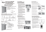
1
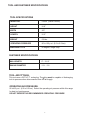
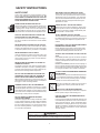
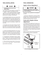
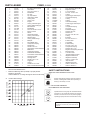
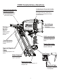
MODEL F325R
Framing Nailer
IMPORTANT!
OPERATING MANUAL AND
SCHEMATIC
DO NOT DESTROY
It is the customers responsibility to have all
operators and service personnel read and
understand this manual.
PRINTED IN U.S.A.
© 2014, Illinois Tool Works Inc.
513057-1
03/14
1
INTRODUCTION
The Paslode® F325R remodeling framing nailer is a quality-built tool designed for use in
residential framing applications. This tool will deliver efficient, dependable performance
when used according to the manufactures guidelines. Please study this manual including
the safety instructions to fully understand the operation of this tool.
TOOL AND FASTENER SPECIFICATIONS ................................................................. 3
SAFETY INSTRUCTIONS ............................................................................................ 4
TOOL INSTALLATION AND OPERATION ................................................................ 5-6
AIR SYSTEMS ............................................................................................................. 7-8
FEATURES AND BENEFITS .......................................................................................... 9
EXPLODED VIEW AND SPARE PARTS LIST ....................................................... 10-11
MAINTENANCE ........................................................................................................ 12-13
TROUBLESHOOTING .................................................................................................. 14
WARRANTY .................................................................................................................. 15
ACCESSORIES ........................................................................................................... 16
2
TOOL AND FASTENER SPECIFICATIONS
TOOL SPECIFICATIONS
MODEL NO.
F325R (Part# 513000)
HEIGHT
12.9”
WIDTH
4.3"
LENGTH
12.3"
WEIGHT
5.9 lbs.
OPERATING PRESSURE
90 to 120 p.s.i. (6.2 to 8.3 bar)
MAGAZINE TYPE
30 degree, Single Strip
FASTENER SPECIFICATIONS
NAIL LENGTH
SHANK DIAMETER
2” - 3-1/4"
.113 - .131
TOOL AIR FITTINGS:
This tool uses a 3/8” N.P.T. male plug. The tting must be capable of discharging
tool air pressure when disconnected from the air supply.
OPERATING AIR PRESSURE:
90 to120 p.s.i. (6.2 to 8.3 bar). Select the operating air pressure within this range
for best tool performance.
DO NOT EXCEED THIS RECOMMENDED OPERATING PRESSURE.
3
SAFETY INSTRUCTIONS
SAFETY FIRST
These safety instructions provide information necessary for safe operation of Paslode® framing tools. DO
NOT ATTEMPT TO OPERATE THE TOOL UNTIL YOU
READ AND UNDERSTAND ALL SAFETY PRECAUTIONS AND MANUAL INSTRUCTIONS.
DISCONNECT THE TOOL WHEN NOT IN USE
Always disconnect the tool from the air line when it
is not in use, when you leave the work area or when
moving the tool to a new location. The tool must
never be left unattended because people who are
not familiar with the tool might handle it and injure
themselves or others.
WEAR EYE AND HEARING PROTECTION
Always wear hearing and eye protection devices, that
conform to ANSI Z87.1 requirements, when operating
or working in the vicinity of a tool. As an employer you
are responsible for enforcing the use of eye protection.
Wear hard hats in environments that require their use.
CARRY THE TOOL ONLY BY THE HANDLE
Always carry the tool by the handle only. Never carry
the tool by the air hose or with the trigger depressed
since you could drive a fastener unintentionally and
injure yourself or someone else.
THE TOOL MUST BE USED ONLY FOR THE PURPOSE FOR WHICH IT WAS DESIGNED
Do not throw the tool on the floor, strike the housing in
any way or use the tool as a hammer to knock material
into place.
DO NOT WEAKEN THE TOOL HOUSING
The tool housing is a pressure vessel and should never
be weakened by having your companyʼs name, area of
work or anything else stamped or engraved into its
surface.
NEVER ENGAGE IN HORSEPLAY WITH THE TOOL
The tool is not a toy so do not use it like one. Never
engage in horseplay with the tool or point it at yourself
or any other person, even if you think it is not loaded.
DISCONNECT THE TOOL WHEN PERFORMING
REPAIRS AND CLEARING JAMS
Never attempt to clear a jam or repair a tool unless
you have disconnected the tool from the air line and
removed all remaining fasteners from the tool.
NEVER ASSUME THE TOOL IS EMPTY
Check the magazine for fasteners that may be left in the
tool. Even if you think the tool is empty or disconnected,
never point it at anyone or yourself. Unseen fasteners
could fire from the tool.
ALWAYS USE THE PROPER FITTING FOR THE
TOOL
Only MALE pneumatic type air connectors should be
fitted to the tool, so that high pressure air in the tool is
vented to atmosphere as soon as the air line is disconnected.
NEVER install FEMALE quick disconnect couplings on
the tool. Female couplings will trap high pressure air in
the tool when the air line is disconnected, leaving the
tool charged and able to drive at least one fastener.
NEVER CLAMP THE TRIGGER IN A LOCKED OR
OPERATING POSITION
The trigger of the tool must never be tampered with,
disabled or clamped in a locked or operating position
since this will cause the tool to drive a fastener any
time the work contacting element depressed.
DO NOT EXCEED THE MAXIMUM RECOMMENDED
AIR PRESSURE
Operate the tool only at the recommended air pressure.
Do not exceed the maximum air pressure marked on
the tool. Be sure the air pressure gauge is operating
properly and check it at least twice a day.
DO NOT LOAD FASTENERS WITH THE AIR LINE
CONNECTED, OR WITH THE TOOL TRIGGER OR
WORK CONTACTING ELEMENT DEPRESSED
When loading fasteners into the tool be sure you
disconnect the air line and that you do not depress
the trigger or work contacting element.
Never use any bottled air or gases such as oxygen to
operate the tool since they could cause the tool to
OPERATE THE TOOL ONLY ON A WORKPIECE
The tool should be operated only when it is in contact
with the workpiece. Even then you should be careful
when fastening thin material or working near the edges
and corners of the workpiece since the fasteners may
drive through or away from the workpiece.
explode.
INSPECT TOOL FOR PROPER OPERATION
Clean the tool at least daily and lubricate as required.
Never operate a dirty or malfunctioning tool.
USE ONLY PASLODE ® RECOMMENDED PARTS
AND FASTENERS
Use only parts and fasteners specifically designed and
recommended by Paslode® for use in the tool and for
and for work to be done. Using unauthorized parts
and fasteners or modifying the tool in any way creates
dangerous situations. Replace all missing warning
labels---refer to tool schematic for correct placement
and part number.
DO NOT DISABLE OR REMOVE THE WORK
CONTACTING ELEMENT
This tool is equipped with a safety mechanism, called
a work contacting element, to help prevent accidental
accidental firing. Never tamper with, disable or remove
the work contacting element. Do not use the tool unless
the work contacting element is working properly. The
tool could fire unexpectedly.
WARNING
Failure to follow any of the above instructions could result in severe personal
injury to tool user and bystanders or cause damage to tool and property.
4
TOOL INSTALLATION
TOOL OPERATION
Depth of Drive Adjustment
Your Paslode tool comes ready for immediate use
and can be installed by following these steps:
®
1. SAFETY - All tool operators and their immediate
supervisors must become familiar with the operator
safety instructions before operating the tool. The
instructions are on page 4 of this manual.
The depth of drive adjustment can be adjusted
two ways.
1. One way is to adjust the air supply to provide
enough drive to meet the proper depth for the
application without exceeding manufactures recommended operating pressure of 120 PSI.
2. Included with each tool are one copy of this
Safety and Maintenance manual and one copy of
the Tool Schematic. Keep these publications for
future reference. An ownership registration card is
also included. This card must be completed and
returned to Paslode immediately to register your
ownership.
Tools with a Depth of Drive
Adjustment
®
2. The depth of drive adjustment is made by turning the thumbwheel on the work contact element.
If the tool is overdriving (the fastener head is
driven below the work surface), the work contact element should be moved downward. If
the fasteners stand up (the head not flush with
the surface), the work contact element should
be moved up.
3. The plastic cap in the air inlet of the tool must be
removed before the male fitting is installed. The tting must be a male pneumatic type that discharges
the air from the tool when the air line is disconnected.
4. Install a filter/regulator/lubricator unit, with a
gauge as close as practical to the tool, preferably
within ten feet. Refer to the Air Systems section of
this manual for air hose requirements and lengths.
In general, no other special installation is required.
Adjust the work contact element until the fastener head depth meets job requirements.
5. If the operator is working at a bench or table,
it is usually best to run the air line underneath the
bench. A small tray under the benchtop can hold
the fastener supply and the tool when not in use.
6. If this tool does not work when it is first connected, do not try to make repairs. Call your Paslode
representative immediately.
ROTATE
THUMBWHEEL
IN EITHER
DIRECTION
®
WORK
CONTACT
ELEMENT
(On tools equipped with this feature)
5
TOOL OPERATION continued
Loading of Nails
Step 1 - Grasp the handle firmly.
Step 2 - Insert one strip of nails into the
rear of the magazine.
Step 3 - Pull the follower to the rear of the
magazine until it is engaged behind
the nails.
Sequential Operation
The sequential operating kit prevents succesive or "bounce"
driving.
Depress the work contacting element and hold it against the
work surface before pulling the trigger.
After each fastener is driven, completely release the trigger
and lift the tool from the work surface.
Switching the Trigger
The tool is manufactured with a trigger that
can be switched from sequential operation to a
bounce drive operation. The trigger is placed in
the sequential operating position when the tool
was manufactured. To switch the trigger to the
bounce operating position, remove the O-ring
and trigger pivot pin from the trigger assembly.
Move the trigger to the bounce operation position
and install the trigger pivot pin and O-ring. The
postion indicator
on the tool should now be
pointing to the
as shown in the illustration.
Sequential
drive position
Precision Placement Driving
■ Grasp the tool handle firmly and place the bottom of the work
contacting element firmly against the workpiece until it is completely depressed.
■ Squeeze the trigger to drive the fastener.
■ Lift the tool from the workpiece.
Pivot pin
and o-ring
■ Repeat the procedure for the next fastener.
Successive (Bounce) Driving
Position
indicator
■ Grasp the handle firmly.
Bounce drive
position
■ Squeeze the trigger and move the tool along the workpiece
with a bouncing motion, depressing the work contacting element
at the points where you want to insert a fastener.
■ Keep the trigger depressed and continue to bounce the work
contacing element against the workpiece, positioning the tool
above as carefully as possible.
■ When the desired number of fasteners have been driven,
release the tool trigger to avoid unintentional fastener discharge.
6
AIR SYSTEMS
Air hoses are not longer than 150 feet.
For air-powered tools to work their best, the air
supply system must be properly installed and
maintained regularly. A drawing in this section
shows a properly installed air supply system.
Handy checklists for installing and maintaining
air supply systems follow.
The air system is lubricated regularly.
A regular maintenance program is followed.
Indoor Air System Installation
-Be certain that:
Filter/Regulator/Lubricator Units
Filter/regulator/lubricator units that can supply
enough air and protection for Paslode® tools
must meet the following specifications:
All pipes supplying air have a large enough
inside diameter to ensure adequate air supply.
The main supply pipe slopes down, away from
the compressor (1/16 inch per foot).
Minimum 3/8 inch NPT port size .
50 micron or fine filters.
Air storage is provided along lengthy air lines.
Regulated pressure from zero to 120 psi.
Pipe line branch outlets are at the top of the
main pipe line.
Lubricators designed for low or changing
airflow.
Cutoff valves are provided at each branch pipe
line throughout the system.
Water legs extend from the bottom of each branch
line.
A refrigerant-type dryer is installed on the system.
Air hoses are kept as short as practical.
A regular maintenance program is followed.
Outdoor Air System Installation
-Be certain that:
A moisture trap and a filter/regulator/lubricator
are installed at the compressor.
Air hoses and fittings are large enough so that air
flow is not restricted. Minimum hose size is 3/8
inch ID with 1/2 inch ID hose used for any application over 25 feet.
7
AIR SYSTEMS - Continued
Calculating Compressor Size
Use the air consumption chart in the Tool
Schematic for each tool when calculating
the operating requirements for the tools.
Paslode® tools are designed to operate
efficently between 90 and 120 psi and should
never be operated at pressure greater than
120 psi.
The air consumption chart will help you find
the correct compressor size for your application that will quickly replenish tool air pressure. To use the chart you will need to know
how many tools will be used and approximately how many fasteners will be driven
each minute by each tool on the line.
Using the equation:
Number of tools X average fasteners/minute/
tool X 1.2 (safety factor) X air consumption
(scfm) @ pressure* (psi) = scfm required.
We can use the following example:
10 tools X 30 fasteners/minute/tool X 1.2 X
0.051scfm* (@100psi) = 18.36 scfm.
*This number is found in the air consumption
chart.
In this example, using the air consumption
chart we find that a compressor providing
at least 19 scfm of air is required. Because
in compressors approximately 1 hp is required
to produce 4 scfm, a compressor of at least
5 hp is required.
AIR CONSUMPTION-SCFM/FASTENER
AIR CONSUMPTION CHART
Calculated Required Piping
For example, given a 20 hp electric compressor
supplying approximately 80 cfm of air at 120 psi
and a main supply pipe length of 350 feet, we see
by the table the minimum main pipe inside diameter required for this application is 1-1/4 inch.
LENGTH OF RUN (FT.)
VOLUME
OF AIR
(CFM)
50-200
30-60
1
1
1¼
1½
1½
60-100
1
1¼
1¼
2
2
100-200
1¼
1½
2
2¼
2½
200-500
2
2½
3
3½
3½
500-1000
2½
3
3½
4
4½
290-500
500-1000
1000-2500
2500-5000
NOMINAL PIPE DIAMETER (IN.)
Pneumatic System Maintenance
- Be certain that:
• Pneumatic ttings are tight and do not leak.
and ensure that automatic draining systems are
operating correctly.
• Air lines are cleared to prevent freezing,
especially in winter.
• Lubricator operation is checked regularly and
ensure it has an adequate supply of lubricant.
.060
ER RT
F
RE HA L
C OO IC
O
T N T AT
I EM
H
C
S
.055
.050
.040
.035
.030
60
70
80
90
100
110
AIR PRESSURE-PSIG
• Only regulated air is being used and that each
regulator is operating properly.
120
8
F325R FEATURES & BENEFITS
Nonslip No-Mar Protection
Tool-Less
Depth of Drive
Prevents scratches of interior work
surfaces and prevents the tool from
sliding on smooth surfaces
Provides precise control
of nail depth (on other side)
Metal
Exhaust Cap
For maximun
durability.
Aggressive
Work Contact
Grabs the wood
when toe nailing.
Dual Mode Trigger
Lock Out
Switches from sequential to
bounce fire.
Eliminates blank
firing.
Ultra Lightweight Design
Bypass Follower
Easy to manuever with less arm
fatigue.
For fast 2-step loading.
Compact
Design
Able to get into
tight spots
Rear Load Magazine
Holds 1 strip or appoximately
41 nails plus lockout.
End Plug
Left/Right Rafter Hook
Accommodates left-or righthanded operators.
9
F325R , 513000
PARTS LEGEND
1
2
3
4
5
* 6
* 7
* 8
* 9
10
* 11
* 12
13
14
15
16
17
* 18
* 19
20
* 21
* 22
* 23
24
25
26
27
28
29
30
31
32
33
34
35
* 36
37
38
511943
511444
511847
408302
513003
511413
513042
201756
202398
511960
539676
511876
511719
1011802
511799
511411
511409
511410
511970
511407
511447
511576
511585
511448
502050
404361
502046
502049
502061
502036
502047
513002
502058
502333
502324
502042
511713
502033
1
1
4
6
1
1
1
1
1
1
1
1
1
1
1
1
1
1
1
1
1
1
1
1
1
1
1
1
1
1
1
1
2
2
1
1
1
1
Nut, Nylon-insert 1/4”-28
Air Deflector
S.H.C.S. #10-24 x 1”
Flat Washer
Top Cap
Top Cap Gasket
Valve Spring, Main
O-Ring, Post
O-Ring, Cap
Poppet
O-Ring, Internal Poppet
O-Ring, External Poppet
Exhaust Seal
Flat Washer
S.H.C.S.1/4-28 x 1-9/16”
Piston “K” Seal
Sleeve
Check Valve Band
O-Ring, Inner Flange
Sleeve Flange
O-Ring, Outer Flange
*
*
*
*
*
Bumper
Driver Blade Seal
Compression Spring
Detent Body
Roll Pin 1/8 x 1/2”
Upper Work Contact Element
Ball Detent
Compression Spring
Thumbwheel Assembly
Lower Work Contact Element
Housing with Grip
Housing Label
Roll Pin 1/8 x 1-1/2”
Trigger Pin
O-Ring
Roll Pin 3/16 x 1-3/8”
Work Contact Element Guide
*
**
Denotes Normal Wear Items.
Make sure Warning Label (513092) is properly affixed.
Replace if necessary.
Label available at no charge through the Service Parts Dept.
➔
Denotes New Change
AIR CONSUMPTION - SCF/FASTENER
*
**
39
40
41
42
43
44
45
46
47
48
49
50
51
52
53
54
55
56
57
58
59
60
61
62
63
64
65
66
67
68
69
70
71
72
73
74
75
76
513066
502014
002187
511714
197913
502044
502059
196345
1015358
511446
502043
092747
502060
502040
511145
091866
502332
502345
402963
513005
502336
502019
502021
511118
500627
502020
403796
511196
513092
442681
502193
513016
513059
502017
404325
502029
502031
502038
1
2
4
4
1
1
1
1
1
1
1
1
1
1
1
1
1
1
1
1
2
1
1
1
1
1
1
1
1
2
1
2
1
2
2
1
1
1
Nose Assembly with Isolators
Magazine Isolator
1/4” Lockwasher
S.H.C.S. 1/4-20 x 7/8”
O-Ring
Upper Trigger Valve Spool
Compression Spring
O-Ring
O-Ring
Valve Pin Assembly
Lower Trigger Valve Spool
O-Ring
Compression Spring
Trip Lever
Dual ModeTrigger
Roll Pin 1/8 x 3/4”
Rafter Hook
S.H.C.S. 5/16-18 x 5/8”
O-Ring
End Plug
S.H.C.S. #10-24 x 1”
Follower Claw
Lockout Bar
Follower Body
S.H.C.S. 8-32 x 1/2”
Compression Spring
Roll Pin 1/8 x 1-1/4”
Negator Drum/Spring Assembly
Warning Label
Lock Nut 1/4-20
Actuation Settings Label
Magazine Wear Rods
Magazine Assembly
B.H.C.S. 1/4-20 x 3/4”
Stop Nut 8-32
Magazine End Cap
B.H.C.S. #8-32 x 1/2”
B.H.C.S. #8-32 x 1”
SAFETY INSTRUCTIONS
WEAR EYE AND HEARING PROTECTION
Always wear hearing protection and eye protection
devices, including side shields when operating or
working in the vicinity of a tool.
DO NOT EXCEED MAXIMUM
•
RECOMMENDED AIR PRESSURE
.090
SCF
Operate the tool using only the recommended air
pressure. Do not exceed the maximum air pressure
marked on the tool. Be sure the air pressure gauge is
operating properly and check it at least twice a day.
Never use any bottled air or gases such as oxygen
to operate the tool since they could cause the tool
to explode.
AIR PRESSURE - PSIG
10
F325R
513000
Piston
Assembly
513008
1
2
55
56
16
3
70
#
120
#
59
58
57
65
#
32
4
4
5
34
35
36
37
33
6
7
Main
Valve
Assembly
511465
8
9
24
38
40
25
51
52
26
➔
11
12
Note: Install check band
with thick side down.
28
29
30
21
130
#
Nose
Assembly
513066
41
42
200
#
74
22
31
66
Magazine
Assembly
513059
65
69
68
23
62
63
73
15
#
75
76
67
72
64
61
Trigger
Assembly
513061
54
27
20
14
Trigger
Valve
Assembly
511460
53
19
13
60
43
44
45
46
47
49 48
50
39
18
10
15
17
Upper WCE
Assembly
502734
20
#
Follower Body
Assembly
513068
71
70
120
#
# Torque Values
IN-LBS
11
MAINTENANCE
❑ Open the drain on the air compressor tank to drain any
moisture at least daily in extremely cold or humid weather.
A few ounces of anti-freeze in the tank will keep the air
free of frost.
Paslode® tools are built for ease of maintenance.
A few simple details will assure trouble-free operation and
long tool life. Anyone who uses or maintains the tool must
read the safety and maintenance instructions. Study the
schematic drawing before starting any repairs on the tool.
Testing the Tool After Servicing
After replacing any part or parts, it is important to check
the tool for proper operation. This ensures that the tool
was put together correctly, is safe to use, and will perform
the job properly.
Air-operated tools must be inspected periodically, and worn
or broken parts must be replaced to keep the tool operating
safely and efficiently. Also the items on the maintenance
chart must be checked often.
❑ Ensure that all hardware is tight.
❑ Ensure that the work contacting element is installed
correctly in relation to the trigger, and that both parts move
freely.
Cold Weather Care
When temperatures are below freezing, tools should be
kept warm by any convenient, safe method. If this is not
possible, the following procedure should be used to warm
up the tools.
❑ Ensure that the magazine is properly attached.
❑ Ensure that the required safety information on the tool
is legible.
❑ Reduce the regulated air pressure to 30 psi.
❑ Use only Paslode® approved fasteners in the tool, and
ensure that they are correct for the application.
❑ Remove all fasteners from the tool.
❑ Collect an air line and blank fire the tool. The reduced
air pressure will be enough to free-fire the tool. Slow speed
operation tends to warm up the moving parts. Slowing up
the piston helps the bumper and the O-rings to become
springy.
❑ Ensure that a male air fitting is securely connected to
the tool.
❑ Test the tool by driving fasteners into a workpiece identical to the tool's application.
❑ Check the tool for air leaks during testing and for the
proper sequence of operation.
❑ Ensure that all fasteners are driven to the same depth
and that the crown of the fastener is flush with the workpiece.
❑ Once the tool is warmed up, readjust the regulator to the
proper working pressure and reload the tool.
Tool Lubrication
❑ Tool operators working outdoors or in unheated areas in
It is most important that the tool be properly lubricated by
keeping the air line lubricator filled and correctly adjusted.
Without proper lubrication the tool will not work properly
and parts will wear prematurely.
Use the proper lubricant in the air line lubricator. The
lubricator should be of low air flow or changing air flow
type, and should be kept filled to the correct level. Use
only Paslodeʼs recommended lubricants. Substitutes may
harm the rubber compounds in the tools O-rings and other
rubber parts. Part No. 403720 is a pneumatic lubricanting
oil specially made for pneumatic applications.
If a filter/regulator/lubricator is not installed on the air system, air operated tools should be lubricated at least once
a day with 6 to 20 drops of oil, depending on the work environment, directly through the male fitting in the tool
housing.
Most minor problems can be resolved quickly and easily
using the maintenance table that follows. If problems persist, contact your Paslode® dealer for assistance.
extremely cold temperatures should also:
Use pneumatic oil with antifreeze in the
lubricator, Part No. 219090 (8oz.)
Once a week, depending on the amount of tool
use, take the tool apart and wash away any sludge
with tool cleaner ( Part No. 219348) to keep the
tool operating efficently.
Cleaning the air-operated tools with solvents removes the
thin coating of grease applied to the cylinder wall and
O-rings at the factory. To replace this coating of grease,
use Chemplex grease (Part No. 403734).
12
MAINTENANCE - Continued
CAUTION
Disconnect the tool when performing
repairs or clearing jams.
MAINTENANCE TABLE
ACTION
WHY
HOW
Drain air line filter(daily).
Prevent accumulation of
mositure and dirt.
Open manual petcock (most
air supply systems have such
a valve).
Keep lubricator filled.
Keep tool lubricated.
Fill with pneumatic tool
lubricant. Part No. 403720.
Clean filter element-then blow
air through filter in direction
opposite to normal flow.
Prevent clogging of filter with
dirt.
Wash with soap and water or
follow manufacturers instructions.
Check that all screws on tool
are tight.
Prevent air leakage and promote efficient operation.
Check screws daily.
Keep work contacting elelment
working properly.
Promote operator safety and
efficient tool operation.
Blow clean daily.
Keep magazine and feeder
mechanism clean.
Prevent jamming of fasteners.
Blow clean daily.
Lubricate "O" rings that are
replaced.
Assure long life and proper
operation of tool.
Use Chemplex grease, Part
No. 403734.
Use only Paslode® replacement
parts.
Keep tool operating efficiently
and maintain Paslode® tool warranty.
Order any repacement parts
needed from your local
Paslode® Dealer.
13
OPERATOR TROUBLESHOOTING
CAUTION
Disconnect the tool when performing
repairs or clearing jams.
PROBLEM
CORRECTIVE ACTION
Adjust work contacting element (retract length).
Fasteners will not drive completely into wood.
Increase air pressure (do not exceed 120 psi).
Increase air flow to tool -- use larger air lines
(3/8 inch ID minimum).
Fasteners penetrate properly during normal
operation, but won't drive fully at faster speeds.
Reduce air pressure.
Fasteners drive too deeply into wood.
Adjust work contacting element (extend length).
Check magazine for proper fasteners. Magazine
follower should slide freely. Clean as needed to
remove debris.
Tools skips during operation - no fasteners are
driven from time to time.
Make sure correct fasteners are being used.
Use fasteners that meet Paslode specifications
only.
Increase air flow to tool -- use larger air lines
(3/8 ID minimum).
Adjust work contacting element where available.
Check magazine for proper fasteners. Fasteners
should slide freely with no follower pressure.
Tool operates, but no fasteners are driven.
Increase air pressure (do not exceed 120psi).
Tighten cap screws.
Air leaks at cap when tool is connected to air.
14
14
TOOL WARRANTY
An Illinois Tool Works Company
888 Forest Edge Drive
Vernon Hills, Illinois 60061
MODEL F325R
Framing Nailer
TOOL WARRANTY AND LIMITATIONS
Paslode® warrants that newly purchased power
fastening tools, parts and accessories will be free
from defects in material and workmanship for the
period shown below, after the date of delivery to
the original user.
ONE-YEAR LIMITED WARRANTY
A one-year warranty will apply to all parts, except
those which are specifically covered by an extended
warranty.
FIVE-YEAR EXTENDED LIMITED WARRANTY
A ve-year warranty will apply to all housing and cap
assembly castings.
WARRANTY STATEMENT
This warranty is limited to tools sold and service requested
in the United States. To obtain information on warranty
service in the United States, refer to the Service Center
listing that was provided with your tool.
Paslode's sole liability hereunder will be to replace any
part or accessory which proves to be defective within the
speci c time period. Any replacement part or accessory
provided in accordance with this warranty will carry a
warranty for the balance of the period of warranty applicable to the part it replaces. This warranty does not apply
to part replacement required due to normal wear.
This warranty is void as to any tool which has been subjected
to misuse, abuse, accidental or intentional damage, use
with fasteners, not meeting Paslodeʼs specification, size,
or quality, improperly maintained, repaired with other than
genuine Paslode® replacement parts, damaged in transit or
handling, or which, in Paslodeʼs opinion, has been altered
or, repaired in a way that affects or detracts from the
performance of the tool.
PASLODE® MAKES NO WARRANTY, EXPRESSED OR
IMPLIED, RELATING TO MERCHANTABILITY, FITNESS, OR OTHERWISE, EXCEPT AS STATED ABOVE, AND
PASLODEʼs LIABILITY AS STATED ABOVE AND AS
ASSUMED ABOVE is in lieu of all other warranties arising
out of, or in connection with, the use and performance of the
tool, except to the extent otherwise provided by applicable law. PASLODE® SHALL IN NO EVENT BE LIABLE
FOR ANY DIRECT, INDIRECT,OR CONSEQUENTIAL
DAMAGES, INCLUDING, BUT NOT LIMITED TO, DAMAGES
WHICH MAY ARISE FROM LOSS OF ANTICIPATED
PROFITS OR PRODUCTION, SPOILAGE OF MATERIALS,
INCREASED COST OF OPERATION, OR OTHERWISE.
Paslode® reserves the right to change specifications, equipment, or
designs at any time without notice and without incurring obligation.
15
ACCESSORIES
Lubricants and Loctite
Loctite 242 (Blue) .20 oz.
Lubricating Oil 16 oz.
Lubricating Oil with Antifreeze 8 oz.
Chemplex 710 Lubricant 1lb.
Part No.
Part No.
Part No.
Part No.
093500
403720
219090
403734
Tool Cleaner
Ideal cleaner for all Paslode ® tools in a 12 oz. aerosol can.
Safety Glasses
Part No. 219348
Clear
Part No. 401382
No Mar Work Contact
Part No. 502234
For technical support call 1-800-222-6990.
To purchase parts and accessories, visit www.itwconstructionparts.com.
An Illinois Tool Works Company
888 Forest Edge Drive
Vernon Hills, Illinois 60061-3105
ACESORIOS
Lubricantes Y Loctite
Loctite 242 (Azul )
Acetite Lubricante 16 oz.
Acetite Lubricante 8 oz .
Lubricante Chemplex 710 1lb.
Pieza No.
Pieza No.
Pieza No.
Pieza No.
093500
403720
219090
403734
Limpiador
El limpiador ideal para todas las herramientas
Lentes de Seguridad
Claros
Pieza No. 219348
Pieza No. 401382
Kit de reparación de parte de F325R
Pieza No. 219389
Contacto de elemento "no-mar"
Pieza No. 502234
Para llamada técnica de apoyo, 1-800-222-6990.
Para comprar las partes y los accesorios, la visita www.itwconstructionparts.com.
PRINTED IN U.S.A.
© 2014, Illinois Tool Works Inc.
An Illinois Tool Works Company
888 Forest Edge Drive
Vernon Hills, Illinois 60061-3105
GARANTÍA
An Illinois Tool Works Company
888 Forest Edge Drive
Vernon Hills, Illinois 60061
TERMINOS DE LA GARANTÍA
Paslode ® garantías que sus herramientas mecánicas,
sus piezas y accesorios, que hayan sido comprados
nuevos, están libres de defectos de material y fabricación por el período indicado más abajo, a partir de
la fecha de compra del comprador original.
Paslode ® asume únicamente la responsabilidad de
reponer cualquier pieza o accesorio que se compruebe
pruebe como defectuoso dentro del período especificado. Cualquier pieza o accesorio de repuesto,
entregado de conformidad con esta garantía, gozará de
la garantía por el período restante de la garantía que
cubría a la pieza o al accesorio originales. Esta garantía
no cubre las piezas que necesitan ser repuestas como
consecuencia de su desgaste normal.
GARANTÍA LIMITADA DE UN AÑO
La garantía limitada de un año cubre todas las piezas,
con excepción de aquellas cubiertas por la extención
de garantía.
Se cancelará esta garantía a cualquier herramienta que
haya sido usada incorrectamente, dañada accidental o
intencionalmente, usada con sujetadores que no
reúnan las especificaciones, el tamaño o la calidad de
Paslode ® o a la que no se le haya dado el man tenimiento
o el uso adecuado, o que haya sido reparada con piezas
que no sean marca Paslode ® o que en opinión de Paslode ®
hayan sido modificadas o reparadas de manera que afecte
o sea contraria al funcionamiento de la herrmienta.
GARANTÍA LIMITADA ADICIONAL DE CINCO AÑOS
La garantía de cinco años cubre todos los armazones
y ensambles de las tapas.
PASLODE ® NO OTORGA NINGUNA GARANTÍA
EXPLÍCITA O IMPLÍCITA CON RESPECTO A LA
COMERCIALIZACIÓN O ADAPTACIÓN AL USO
PREVISTO, O DE CUALQUIER OTRA NATURALEZA,
CON EXCEPCIÓN DE LO DECLARADO ANTERIORMENTE, y la responsabilidad de PASLODE ® TAL COMO
SE INDICA Y SE ASUME MÁS ARRIBA reemplaza a
todas las otras garantías que resulten o estén relacionadas con el uso y funcionamiento de la herramienta
mienta, excepto según lo estipulen las leyes pertinentes. PASLODE ® NO SERÁ RESPONSABLE EN NINGÚN
CASO POR NINGÚN DAÑO DIRECTO, INDIRECTO
O CONSECUENTE INCLUYENDO, PERO SIN LIMITARSE,
CUALQUIER DAÑO RESULTADO DE LA PÉRDIDA
DE PRODUCCIÓN O GANAN CIAS ANTICIPADAS,
EL DETERIORO DE MATERIALES, AUMENTOS EN
EL COSTO DE OPERACIÓN O CUALQUIER OTRO.
DECLARACIÓN DE LA GARANTÍA
Esta garantía esta limitada a las herramientas vendidas y revisadas en los Estados Unidos. Para obtener
mas información sobre el servicio de garantía en los
Estados Unido, véa la lista de Centros de Servicio que
fue proporcionada con su herramienta.
Paslode se reserva el derecho de cambiar las especificaciones, el equipo o los
diseños en cualquier momento, sin aviso previo y sin incurrir en obligación alguna.
15
DETECCION Y CORRECCION DE FALLAS
PRECAUCIÓN
Desconecte la herramienta al hacer cualquier
reparación o eliminar cualquier obstrucción.
PROBLEMA
SOLUCIÓN
Los sujetadores no penetran completamente en la
madera.
Cambie la posición del elemento de contacto (Retraiga
la longitud).
Aumente la presión de aire (no debe exceder 120 psi).
Los sujetadores penetran bien durante las operaciones
normales, pero fallan a velocidades más altas.
Aumente el flujo de aire a la herramienta; use líneas
de aire más grandes (3/8” de diámetro como mínimo).
Los sujetadores penetran demasiado en la madera.
Cambie la posición del elemento de contacto (Extienda la longitud).
Reduzca la presión de aire.
Los sujetadores se acumulan en la punta de la herramienta.
Abra el seguro delantero, quite el sujetador obstruido y
cierre bien el segurro.
La herramienta “salta” mientras está funcionando; de
vez en cuando no impulsa sujetadores.
Compruebe si el cargador tiene los sujetadores apropiados. El transportador debe deslizarse sin dificultad.
Límpielo para quitar cualquier suciedad.
Verifique que se usen los sujetadores apropiados.
Use solamente sujetadores que reúnan las especificaciones de Paslode®.
Aumente el flujo de aire a la herramienta; use líneas
de aire más grandes (3/8” de diámetro como mínimo).
Ajuste el elemento de contacto donde sea posible.
Compruebe si el cargador tiene los sujetadores apropiados. Los sujetadores deben deslizarse libremente
sin presión del transportador.
La herramienta funciona, pero no dispara sujetadores.
Abra el seguro delantero o afloje el botón del cargador
y revise si hay suciedad o alguna obstrucción en el
área de la punta. Límpiela si es necesario.
Aumente la presión de aire (no debe exceder 120 psi).
Apriete los tornillos.
Hay pérdidas de aire en la cubierta cuando la herramienta está conectada a la línea de aire.
14
MANTENIMIENTO (continuación)
PRECAUCIÓN
Desconecte la herramienta al hacer cualquier
reparación o eliminar cualquier obstrucción.
TABLA DE MANTENIMIENTO
ACTIVIDAD
POR QUE
COMO
Drene el filtro de la línea de aire a
diario.
Para evitar que se acumulen la
humedad y la suciedad.
Abra la llave de escape.
(La mayoría de los sistemas
neumáticos la tienen.)
Mantenga lleno el lubricador.
Para mantener lubricada la
herramienta.
Llene con lubricante neumático
N° 403720 (474 ml).
Limpie el elemento del filtro;
luego, sople aire a través del filtro
en la dirección opuesta a la
corriente normal.
Para evitar que la suciedad obstruya el filtro.
Lave con agua y jabón, o siga las
instrucciones del fabricante.
Verifique que todos los tornillos de
la herramienta estén apretados.
Para evitar pérdidas de aire y
asegurar el buen funcionamiento
de la herramienta.
Revise los tornillos a diario.
Revise si el elemento de contacto
funciona correctamente.
Para promover la seguridad del
Límpielo con aire a diario.
operador y el buen funcionamiento
de la herramienta.
Mantenga limpios los mecanismos
del cargador y del alimentador.
Par prevenir que se obstruyan los
sujetadores.
Límpielos con aire a diario.
Lubrique los anillos-o que se
hayan reemplazado.
Para prolongar la vida de la
herramienta y su funcionamiento
adecuado.
Use grasa lubricante Chemplex
N° 403734.
Use solamente piezas de repuesto
Paslode ® .
Para que la herramienta continúe
funcionando eficientemente y
mantener vigente la garantía de
Paslode ®.
Solicite al representante de
Paslode® cualquier pieza
de repuesto que necesite.
13
MANTENIMIENTO
El mantenimiento de cualquier herramienta Paslode ®
es simple. Su funcionamiento sin problemas y la prolongación de la vida de la herramienta se logran siguiendo un
sencillo procedimiento. Las personas encargadas de
usar y mantener la herramienta deben leer las instrucciones de seguridad y mantenemiento. Estudie los diagramas antes de hacer cualquier reparación.
Las herramientas neumáticas deben revisarse periódicamente, y se deben cambiar las piezas gastadas o deterioradas para que la herramienta siga funcionando con
eficiencia y sin peligro. Además, se debe revisar la tabla
de mantenimiento frecuentemente.
Cuando Hace Mucho Frio
Cuando la temperatura es inferior a la de congelamiento,
las herramientas deben mantenerse a la temperatura
ambiente por el método más seguro y conveniente. De lo
contrario, aconsejamos seguir el siguiente procedimiento
para calentar las piezas de la herramienta.
■ Disminuya la presión regulada del aire a 30 psi
■ Quite todos los sujetadores de la herramienta.
■ Conecte una línea de aire y dispare la herramienta
sin clavos. La presión reducida del aire será suficiente
para lograrlo. El funionamiento a poca velocidad tiene
la tendencia de calentar las partes movibles. Dis
minuyendo la velocidad del pistón le da cierta elasticidad
al amortiguador y los anillos-o.
PRECAUCIÓN
Nunca dispare la herramienta sin clavos a
alta presión.
■
■
■
Una vez que la herramienta se haya calentado, ajuste
nuevamente el regulador a la presión apropiada para
trabajar y cargue de nuevo la herramienta.
Los operadores que trabajen al aire libre o en áreas
sin calefacción con temperaturas extremadamente
frías también tienen que usar en el lubricador el aceite
neumático con anticongelante N° 219090 (8 oz.).
Una vez por semana, según el uso que le dé a su
herramienta, desármela y lávela con el solvente N°
219348, para eliminar cualquier suciedad y asegurar
que la herramienta siga funcionando bien.
PRECAUCIÓN
Nunca use queroseno ni ningún solvente
inflamable par limpiar la herramienta.
Al usar solventes para limpiar herramientas neumáticas se
destruye la delgada capa de grasa lubricante, que se aplica en la fábrica, de la pared del cilindro y de los anillos-o.
Use grasa Chemplex N° 403734 para reemplazar la capa
de grasa lubricante.
■
Abra, por lo menos diariamente, el drenaje del tanque
del compresor del aire para eliminar cualquier humedad,
cuando haga mucho frío o el grado de humedad sea
muy alto. Poniendo una pequeña cantidad de descon
gelante en el tanque evitará que la humedad se congele.
Probar la Herramienta Después de Darle
Servicio
Después de reemplazar una o más piezas, es importante
comprobar si la herramienta funciona como es debido.
Esto asegura que todas las piezas estén puestas correctamente, que la herramienta esté segura y que funcione correctamente.
■ Verifique que ninguna pieza esté floja.
■ Compruebe que el elemento de contacto haya sido
correctamente instalado en relación con el gatillo y
que ambas piezas se muevan libremente.
■ Verifique que el cargador esté colocado correctamente.
■
■
■
■
■
■
Verifique que la información sobre seguridad, que
está en la herramienta, sea legible.
Use solamente sujetadores aprobados por Paslode®
y compruebe que sean los apropiados para su aplicación.
Verifique que se haya conectado firmemente un adaptador macho a la herramienta.
Pruebe la herramienta impulsando sujetadores en un
material de trabajo idéntico al de la aplicación.
Verifique que no haya pérdidas de aire en la herramienta durante las pruebas y revise la secuencia apropiada de funcionamiento.
Asegure que todos los sujetadores sean impulsados
a la misma profundidad y que la cabeza del jujetador
esté al ras con el material de trabajo.
Lubricación de la Herramienta
Es muy importante lubricar la herramienta correctamente,
manteniendo lleno el lubricador de la línea de aire y correctamente regulado. Sin la lubricación apropiada, la herramienta no funcionará como es debido y sus piezas se
gastarán prematuramente.
Use el lubricante apropiado en el lubricador de la línea de
aire. El lubricador debe ser para corriente de aire baja o
variable, y tiene que estar lleno hasta el nivel apropiado
por Paslode® porque otros lubricantes podrian dañar el
caucho de los anillos-o y otras piezas de caucho. El lubricante N° 403720 (474 ml) es un aceite lubricante especial
mente diseñado para aplicaciones neumáticas.
Si no se instala un filtro/regulador/lubricador en el sistema
neumático, las herramientas neumáticas deben ser lubricadas, por lo menos, diariamente, poniendo entre 6 y 20
gotas de aceite, según sea el tipo de trabajo que se realice,
directamente a través del adaptador macho.
Usando la siguiente tabla de mantenimiento es posible resolver rápidamente y fácilmente la mayoría de los pequeños problemas. Si un determinado problema persiste,
comuniquese con el representante de Paslode ®.
12
F325R
513000
Montaje
del Pistón
1
513008
2
55
56
16
3
70
#
59
58
57
120
#
65
#
32
4
4
33
5
34
6
7
Válvula
Principal
511465
8
9
24
38
40
25
11
12
51
52
26
➔
Nota:
Manga de instalación
verificación banda
gruesa hacia abajo.
28
29
30
21
130
#
Montaje del
Gatillo
513061
Montaje
la Nariz
513066
41
42
200
#
74
22
31
66
511460
54
27
20
14
Montaje de
a Válvula
del Gatillo
53
19
13
60
43
44
45
46
47
49 48
50
39
18
10
15
17
35
36
37
Montaje del
Elementode
Contacto
Superior
502734
68
23
Montaje del
Magazine
65
69
73
15
#
75
76
67
513059
72
64
61
62
63
20
#
De Montaje
de Carrocerías
del Seguidor
513068
71
70
120
#
# Torque Values
IN-LBS
11
F325R , 513000
LIS TA DE PIEZAS
1
2
3
4
5
* 6
* 7
* 8
* 9
10
* 11
* 12
13
14
15
16
17
* 18
* 19
20
* 21
* 22
* 23
24
25
26
27
28
29
30
31
32
33
34
35
* 36
37
38
*
**
511943
511444
511847
408302
513003
511413
513042
201756
202398
511960
539676
511876
511719
1011802
511799
511411
511409
511410
511970
511407
511447
511576
511585
511448
502050
404361
502046
502049
502061
502036
502047
513002
502058
502333
502324
502042
511713
502033
1
1
4
6
1
1
1
1
1
1
1
1
1
1
1
1
1
1
1
1
1
1
1
1
1
1
1
1
1
1
1
1
2
2
1
1
1
1
Nut, Nylon-insert 1/4”-28
Air Deflector
S.H.C.S. #10-24 x 1”
Flat Washer
Top Cap
Top Cap Gasket
Valve Spring, Main
O-Ring, Post
O-Ring, Cap
Poppet
O-Ring, Internal Poppet
O-Ring, External Poppet
Exhaust Seal
Flat Washer
S.H.C.S.1/4-28 x 1-9/16”
Piston “K” Seal
Sleeve
Check Valve Band
O-Ring, Inner Flange
Sleeve Flange
O-Ring, Outer Flange
*
*
*
*
*
Bumper
Driver Blade Seal
Compression Spring
Detent Body
Roll Pin 1/8 x 1/2”
Upper Work Contact Element
Ball Detent
Compression Spring
Thumbwheel Assembly
Lower Work Contact Element
Housing with Grip
Housing Label
Roll Pin 1/8 x 1-1/2”
Trigger Pin
O-Ring
Roll Pin 3/16 x 1-3/8”
Work Contact Element Guide
513066
502014
002187
511714
197913
502044
502059
196345
1015358
511446
502043
092747
502060
502040
511145
091866
502332
502345
402963
513005
502336
502019
502021
511118
500627
502020
403796
511196
513092
442681
502193
513016
513059
502017
404325
502029
502031
502038
1
2
4
4
1
1
1
1
1
1
1
1
1
1
1
1
1
1
1
1
2
1
1
1
1
1
1
1
1
2
1
2
1
2
2
1
1
1
Nose Assembly with Isolators
Magazine Isolator
1/4” Lockwasher
S.H.C.S. 1/4-20 x 7/8”
O-Ring
Upper Trigger Valve Spool
Compression Spring
O-Ring
O-Ring
Valve Pin Assembly
Lower Trigger Valve Spool
O-Ring
Compression Spring
Trip Lever
Dual ModeTrigger
Roll Pin 1/8 x 3/4”
Rafter Hook
S.H.C.S. 5/16-18 x 5/8”
O-Ring
End Plug
S.H.C.S. #10-24 x 1”
Follower Claw
Lockout Bar
Follower Body
S.H.C.S. 8-32 x 1/2”
Compression Spring
Roll Pin 1/8 x 1-1/4”
Negator Drum/Spring Assembly
Warning Label
Lock Nut 1/4-20
Actuation Settings Label
Magazine Wear Rods
Magazine Assembly
B.H.C.S. 1/4-20 x 3/4”
Stop Nut 8-32
Magazine End Cap
B.H.C.S. #8-32 x 1/2”
B.H.C.S. #8-32 x 1”
INSTRUCCIONES DE SEGURIDAD
Indica piezas de desgaste normal
Asegure que la Etiqueta de Advertencia (513092) este bien pegada
pegada. Reemplaze si es necesario. La etiqueta esta disponible
sin costo adicional a traves del Departamento de Servicio.
USE PROTECCIÓN PARA OJOS Y OÍDOS.
➔ Indica un cambio nuevo .
AIR CONSUMPTION - SCF/FASTENER
*
**
39
40
41
42
43
44
45
46
47
48
49
50
51
52
53
54
55
56
57
58
59
60
61
62
63
64
65
66
67
68
69
70
71
72
73
74
75
76
Siempre use protección para oídos y equipo de seguridad para los ojos, incluyendo protectores laterales
cuando este manejando o trabajando en los alrededores de una herramienta.
•
NO SOBRE PASE LA MAXIMA PRESIÓN DE
AIRE RECOMENDADA
.090
SCF
Solo opere la herramienta usando la presión de aire
recomendada. No sobre pase la maxima presión de
aire marcada sobre la herramienta. Asegure que el
indicador de presi ón de aire este trabajando bien y
reviselo por lo menos dos veces al día.
Nunca use algún aire o gas embotellado tal como el
oxígeno para funcionar la herramienta ya que pueden
causar que la herramienta explote.
AIR PRESSURE - PSIG
10
F 325 R Características y Beneficios
Antideslizante Protección No-Mar
Ajuste de Profundidad Sin
Uso de Herramienta
Evita los arañazos de las superficies
de trabajo interiores y evita que la
herramienta se deslizamiento sobre
superficies lisas
Proporciona control preciso
de la profundidad de clavo
(sobre lado opuesto)
Tapa de Escape
Hecha de Metal
Contacto
Agresivo
Para máxima durabilidad
Agarra la
madera cuando
sujeta clavos
oblicuos
Gatillo en modo dual
Cambia de disparos en
secuencia a disparos en
rebote
Cierre de Disparo
Elimina disparos en
blanco
Diseño Ultra Liviano
Fácil de manejar con menos
cansancio del brazo
Desvío del Seguidor de
Clavos
Para carga rápida en dos
pasos
Tapón Trasero
Diseño Compacto
Puede entrar en
lugares apretados
Depósito de Ca rga
Capacidad de 1 tira de clavos o 41
bloqueo más.
Gancho de Vigas
Ensamblé al derencho
Ó al izquierdo.
9
SISTEMAS NEUMATICOS (continuación)
Cómo Calcular la Tubería Necesaria
Por ejemplo, si un compresor eléctrico de 20 hp
proporciona aproximadamente 80 pies³/min. de aire a
120 psi y la longitud de la línea principal es de 106.70
m, la tabla indica que el diámetro interior de la línea
principal necesario para esta aplicación debe ser de
1-1/4 pulgadas como mínimo.
Cómo Calcular el Tamaño del Compresor
Use la tabla de consumo de aire en el esquema de
cada herramienta para calcular los requisitos de
funcionamiento de las herramientas. Las herramientas Paslode ® han sido diseñadas para funcionar
eficientemente entre 90 y 120 psi, y nunca se deben
usar a presiones superiores a 120 psi. La tabla de
consumo de aire le permitirá encontrar el tamaño
correcto del compresor para reponer rápidamente la
presión del aire en su herramienta.
Para usar la tabla necesita saber cuántas herramientas se usarán y aproximadamente cuántos sujetadores aplicará, por minuto, cada herramienta de la línea.
Use esta ecuación:
Número de herramientas X promedio de
sujetadores/minuto/herramienta X 1.2 (factor
de seguridad) X consumo de aire (pies³/min./
estándar) @ presión* (psi) = pies³/min./
estándar requeridos
Importante: Presión de Aire (80-100 psi)
Mantenimiento del Sistema Neumático
- Asegure Que:
Por ejemplo:
10 herramientas X 30 sujetadores/minuto/
herramienta X 1.2 X 0.051 pies³/min./
estándar* (@ 100 psi) = 18.36 pies³/min./
estándar.
■
Los adaptadores neumáticos estén apretados y
no haya pérdidas.
■
Las columnas de agua, o los filtros y las líneas
de aire se drenen diariamente, y que los sistemas de drenaje automáticos funcionen correctamente.
■
Las líneas de aire estén limpias para evitar que
se congelen, especialmente en invierno.
■
El funcionamineto del lubricador se examine
periódicamente y que el suministro de lubricante
sea adecuado (Pieza N° 403720).
■
Se limpie el filtro cada seis meses.
■
Sólo se use aire regulado y que cada regulador
funcione correctamente.
* Esta cifra aparece en la tabla de Consumo de Aire.
Usando la tabla de consumo de aire, este ejemplo
demuestra que se necesita un compresor que proporcione 19 pies³/min./estándar de aire, por lo menos.
Como en compresores se necesita aproximadamente
1 hp para proporcionar 4 pies³/min./estándar, se requiere, por lo menos, un compresor de 5 hp.
8
SISTEMAS NEUMÁTICOS
■
Las mangueras de aire no midan más de 45.70 m
de longitud.
■
El sistema neumático sea lubricado
periódicamente.
■
Se siga un programa regular de mantenimiento.
El sistema neumático debe estar correctamente instalado y recibir mantenimiento periódicamente para
que todas las herramientas de potencia neumática
funcionen bien. El diagrama de más abajo muestra
un sistema neumático correctamente instalado. A
continuación se detallan las revisiones necesarias
para la instalación y el mantenimiento de los sistemas
neumáticos.
Unidades de Filtro/Regulador/Lubricador
Instalación de Un Sistema Neumático
para Interiores
- Asegure Que:
■
Tamaño mínimo del orificio a presión y tempera
tura normales de 3/8 de pulgada
■
Filtros de 50 micrones o más finos
■
Presión regulada de 0 a 120 psi
■
Lubricadores diseñados para corriente de aire
baja o variable
■
Las unidades de filtro/regulador/lubricador capaces
de proporcionar aire y proetección suficientes a las
herramientas Paslode ® deben tener las siguientes
características:
El diámetro interior de todas las líneas que
suministran aire sea bastante grande como para
garantizar un suministro de aire adecuado.
■
La línea principal tenga una inclinación de (1/16
de pulgada por pie) a partir del compressor.
■
Existen almacenamientos de aire a lo largo de las
líneas muy largas.
■
Las salidas de aire en las líneas secundarias
estén en la parte superior de la línea principal.
■
Existen válvulas de cierre en cada una de las
líneas secundarias de todo el sistema.
■
Las columnas de agua se extiendan desde el
extremo inferior de cada línea secundaria.
■
Se haya instalado en el sistema un secador tipo
refrigerante.
■
Las mangueras de aire sean tan cortas como sea
posible.
■
Se siga un programa regular de mantenimiento.
Instalación de Un Sistema Neumático
para Exteriores
- Asegure Que:
■
Se hayan instalado en el compresor un colector
de humedad y un filtro/regulador/lubricador.
■
Las mangueras de aire y los adaptadores tengan
la longitud suficiente para que el aire circule sin
problemas. El diámetro mínimo de una manguera
de aire es de 3/8 de pulgada y de 1/2 pulgada
para cualquier apalicación de más de 7.60 m.
23
7
FUNCIONAMIENTO DE LA
HERRAMIENTA (continuación)
Funcionamiento en secuencia
El juego de funcionamiento en secuencia evita los
impulsos sucesivos o "de rebote".
Sujetadores
■ Oprima el elemento de contacto y manténgalo
apoyado contra el material de trabajo antes de
apreter el gatillo.
Paso 1 Tome firmamente el mango.
Paso 2 Insertar uno o uno tiras de clavos en parte
atras del cargador.
■ Después de haber impulsado cada sujetador,
suelte completamente el gatillo y levante la herramienta del material de trabajo.
Paso 3 Hale el seguidor hasta que conecte con
la oparte trasera del cargador.
Cambio de gatillo
La herramienta ha sido manufacturada para cambiar del posición secuencial a operacion por salto
(bounce drive). la posición de manufactura del
gatillo es secuencia. Para cambiar el gatillo a la
posición de impulso por salto, remover el anillo-o
y el pino pasador del sistemade ensamblado del
gatillo. Mover el gatillo a la posición de salto y
coloque el pino pasador y el anillo-o. El indicador
de posición en la herramienta debe ahora indicar
como se muestra en la ilustración.
▼
Posición de disparo
secuencial
Colocación precisa
■ Tome firmamente la herramienta por el mango
y sosténgala de modo que el base del elemento
de contacto quede bien apoyada en el material de
trabajo.
■ Apriete el gatillo para disparar el sujetador.
■ Separe la herramienta del material de trabajo.
Pino pasador y
anillo-o
Indicador
de posición
■ Repita el mismo procedimiento con el próximo
sujetador.
Impulsos sucesivos (de rebote)
■
Tome la herramienta firmemente por el mango.
■ Apriete el gatillo y mueva la herramienta a lo
largo del material de trabajo con un movimiento de
rebote, oprimiendo el elemento de contacto en los
lugares donde quiera colocar un sujetador.
Posición de impulso
por salto
■ Manteniendo apretado el gatillo, continúe
haciendo rebotar el elemento de contacto contra
el material de trabajo, colocando cuidadosamente
la herramienta.
■ Una vez que haya colocado todos los sujetadores necesarios, deje de oprimir el gatillo para
evitar que salgan más.
PELIGRO
No sujete ni sostenga el gatillo con ninguna
otra cosa que no sea la mano.
22
6
INSTALACION DE LA
HERRAMIENTA
FUNCIONAMIENTO DE LA
HERRAMIENTA
Regulación de la profundida de colocación (en herramientas que tienen esta car-
PELIGRO
La presión de aire en la herramienta nunca
debe exceder 120 psi.
acterística)
PELIGRO
Apunte la herramienta en alguna dirección en
que no haya peligro. Deconéctela de la fuente
de aire comprimido y quítele todos los
sujetadores.
Su herramienta Paslode está lista para usarse y se
puede unstalar siguiendo estos pasos:
®
1. SEGURIDAD: Antes de usar la herramienta, todos
los operadores y sus supervisores inmediatos deben
familiarizarse con las instrucciobnes de seguridad de la
página 4 de este manual.
La profundidad de colocaión se logra regulando la
tuerca de ajuste a sea el elemento de contacto.
2. Con cada herramienta se entrega una copia de este
manual. Conserve este manual para cualquiera consulta
futura. Además, se incluye una targeta de rehistro, que
debe llenarse y devolverse inmediatamente a Paslode ®
para que su herramienta quede registrada.
Si la herramienta excede la profundidad deseada (la
cabeza del sujetador es impulsada por debajo de la
superfice de trabajo), baje el elemento de contacto. Si
los sujetadores sobresalen (la cabeza del sujetador no
está al mismo nivel que la superficie de trabajo), suba
el elemento de contacto.
3. Quite la cubierta plástica en la entrada del aire de la
herrmienta antes de instalar el adaptador macho. Se
requiere un adaptador neumático tipo macho, que descargue el aire de la herramienta cuando se desconecte la
línea de aire comprimido.
Mueva el elemento de contacto hasta que la cabeza del
sujetador quede a la profundidad deseada.
4. Instale una unidad de filtro/regulador/lubricador con
un calibre, tan cercano al de la herramienta como sea
posible, de preferencia a menos de tres metros. Consulte le sección Sustemas Neumáticos de este manual
sobre la longitud y los requisitos de las mangueras de
aire comprimido. En general, no se exige ninguna otra
instalación especial.
5. Si el operador usa una mesa para trabajar. se aconseja colocar la línea de aire comprimido debajo de la
misma. Se puede colocar una pequeña bandeja en la
parte inferior de la mesa para quardar los sujetadores y
la herramienta cuando no están un uso.
Tuerca de
ajuste
6. Si la herramienta no funciona cuando se conecta por
primera vez, no trate de repararla; llame de inmediato al
representate de Paslode ® .
Elemento de
contacto
5
INSTRUCCIONES DE SEGURIDAD
LA SEGURIDAD ESTA PRIMERO
DESCONECTE LA HERRAMIENTA CUANDO NO LA
ESTE USANDO
Estas instrucciones proporcionan la información necesatia para
el funcionamiento sin peligrode las herramientas Paslode®.
No trate de usar su herramienta hasta que no haya léido y
entendido todas las precauciones de seguridad y las
instrucciones de este manual.
Siempre desconecte la herramienta de la línea de aire comprimdo
cuando no la esté usando o al dejar su lugar de trabajo. Nunca la
descuide, porque cualquier persona que no esté familiarizada con
ella podría lastimarse o lastimar otros.
PROTEJASE LOS OJOS Y LOS OIDOS
Use siempre el equipo adecuado para protegerse los ojos
y los oídos que sea conforme con ANSI Z87, meintras usa
una herramienta o trabaja cerca de una herramienta en uso.
Como empleador usted es responsable de imponer el usp
del la porteccion de ojo. Lleve sombreros duros en los
ambientes que requieren su uso.
TOME LA HERRAMIENTA SOLAMENTE POR EL
MANGO
Siempre tome la herramienta sólo por el mango. Nunca la tome
por la manguera o con el gatillo oprimido, porque se podría
disparar un sujetador y herirlo o herir a otra persona.
NO ALTERE EL ARMAZON DE LA HERRAMIENTA
El armazón de la herramienta es un recipiente a presión y nunca se
debe grabar en su superficie el nombre de su compañia, el del área
de trabajo, ni ningún otro detalle.
USE SU HERRAMIENTA SOLAMENTE PARA EL
PROPOSITO CON QUE FUE DISEÑADA
No arroje la herramienta al suelo; no golpee el armazón ni la use
como un martillo.
DESCONECTE LA HERRAMIENTA PARA HACER
REPARACIONES O ELIMINAR OBSTRUCCIONES
Nunca trate de eliminar obstrucciones o reparar una herramienta
sin haberla desconectado de la línea de aire compromido y quitado
todos los sujetadores.
NUNCA USE LA HERRAMIENTA PARA JUGUETEAR
Esta herramienta no es un juguete; por lo tanto no la trate como
tal. Nunca juguetee con ella, ni se apunte a usted mismo ni a otra
persona, aun cuando crea que no está cargada.
NUNCA ASUMAQUE LA HERRAMIENTA ESTA VACIA
USE SIEMPRE LOS ADAPTADORES APROPIADOS
PARA SU HERRAMIENTA
NUNCA SUJETE EL GATILLO EN LA POSICION DE
CIERRE O DE FUNCIONAMIENTO
NUNCA coloque enlaces HEMBRAS de desconexíon rápida en la
herramienta, porque atrapan el aire a alta presíon al desconectar
la línea de aire comprimido, dejándola cargada y lista para disparar
por lo menos un sujetador.
Se debe conectar a la herramienta solamente conectores neumáticos
MACHOS, para permitir que el aire de alta presíon salga tan pronto
como se desconecte la línea de aire comprimido.
Verfique que ho haya sujetadores en elcargador. Aun cuando crea
que está vacía o desconectada, nunca se apunte ni apunte a otra
persona con la herramienta, porque podría dispararse un sujetador
que no esté a la vista.
Nunca se debe manipular indebidamente o dejar inoperante el
gatillo, o sujetarlo en la posición de cierre o defuncionamiento,
porque se podría disparar un sujetador al oprimirse el elemento de
contacto.
NO EXCEDA LA PRESION NEUMATICA MAXIMA
RECOMENDADA
La herramienta debe funcionar sólo con la presíon neumática
recomendada. No exceda la presíon neumática máxima marcada
en la herramienta. Verifique por lo menos dos veces al día que el
calibre de la presíon neumática funcione correctamente.
NO CARGUE SUJETADORES CUANDO LA LINEA DE
AIRE COMPRIMIDO ESTE CONECTADA, O CUANDO
EL GATILLO O EL ELEMENTO DE CONTACTO ESTE
OPRIMIDO.
Nuna use aire o gases envasado, como el oxígeno, para hacer
funcionar la herramienta porque podrían hacer que explotara.
Antes de cargar sujetadores en la herramienta, verifique que la
línea de aire comprimido esté desconectada y que ni el gatillo ni
el elemento de contacto estén oprimidos.
INSPECCIONE LA HERRAMIENTA PARA LA
OPERACION APROPIADA
Limpie diariamente la herramienta y lubríquela como se recomenda.
Nunca trate de hacer funcionar una herramienta sucia o defectuosa.
USE LA HERRAMIENTA SOLAMENTE SOBRE UN MATERIAL DE TRABAJO
La herramienta debe funcionar sólo cuando esté en contacto con el
material de trabajo. Debe tener mucho cuidado cuando el material
sea delagado o trabaje cerca de las aristas del mismo, porque los
sujetadores podrían atravesar o salirse del material.
USE SOLAMENTE PIEZAS Y SUJETADORES
RECOMENDADOS POR PASLODE
Use sólo piezas y sujetadores específicamente diseñados y
recomendados por Paslode para usar con esa herramienta y para
la tarea requerida. Si se usan piezas o sujetadores no autorizados
o se modifica de alguna forma la herramienta, se pueden crear
situaciones peligrosas. Vuelva a colocar todas las etiquetas de
precaucíon que flaten. Consulte el diagrama de la herramienta
sobre el número de cada parte y su ubligación correcta.
NO DEJE INOPERANTE NI QUITE EL ELEMENTO DE
CONTACTO
Esta herramienta está equipada con un mecanismo de seguridad,
llamado elemento de contacto, para prevenir cualquier disparo
accidental. Nunca manipule indebidamente, deje inoperante, ni
quite el elemento de contacto. No use la herramienta a menos que
dicho elemento funcione correctamente, porque podría producirse
un disparo imprevisto.
PELIGRO
La falta de observación de cualquiera de estas instrucciones puede ser causa de graves
lesiones personales, tanto al operador de la herramienta comoa quienes estén cerca de
ella o de daños materiales o a la herramienta.
4
SPECIFICACIONES DE LA HERRAMIENTA Y LOS SUJETADORES
SPECIFICACIONES de la HERRAMIENTA
MODELO NO.
F325R (5130000)
ALTURA
12.9”
ANCHO
4.3"
LARGO
12.3"
PESO
5.9 lbs.
PRESION de OPERACION
90 hasta 120 p.s.i. (6.2 hasta 8.3 bar)
TIPO DE CARGADOR
30 grados, la Franja de
SPECIFICACIONES de los SUJETADORES
LONGITUD DEL CLAVO
2”- 3-1/4"
DIAMETRO
.113 - .131
ACOPLAMIENTO DE AIRE:
Esta herramienta utiliza un enchufe de 3/8" N.P.T. El acoplamiento debe ser capaz
de descargar la presion de aire en la herramienta cuando sea desconectado del
suministro de aire.
OPERACION de PRESION de AIRE:
90 hasta120 p.s.i. (6.2 hasta 8.3 bar). Para mjor funcionamiento seleccionar la
presion de aire en el rango indicado.
NO EXCEDA LA PRESIóN DE AIRE RECOMENDADA
3
INTRODUCCION
La herramienta Paslode® F325R clavadora remodelación es una herramienta de calidad,
diseñada para uso en aplicaciones residencial. Esta herramienta le provera confiabilidad
y eficencia cuando sea usada acorde con las reglas del fabricante. Lea cudadosamente
este manual y las instrucciones de seguridad para comprender como usar le herrminienta
correctamente.
CONTENIDO
SPECIFICACIONES DEL LA HERRAMINETA Y SUS SUJETADORES.............................3
INSTRUCCIONES DE SEGURIDAD................................................................................... 4
INSTALACION Y OPERACION DEL LA HERRAMINETA................................................5-6
SISTEMAS DE AIRES......................................................................................................7-8
BENEFICIOS DEL LA HERRAMIENTA.............................................................................. 9
VISTA EXPANDIDA CON LISTADO DE PIEZAS..........................................................10-11
MANTENIMIENTO.........................................................................................................12-13
DETECCION Y CORRECION DE FALLAS........................................................................14
GARANTIA.........................................................................................................................15
ACESORIOS.......................................................................................................................16
2
MODELO F325R
Framing Clavadora
¡IMPORTANTE!
NO DESTRUYE ESTE MANUAL
El cliente tiene la responsibilidad de que todo
el personal de operaciones y servicio lea y
entienda este manual.
Manual de Funcionamiento y
Esquema