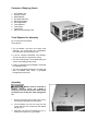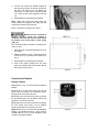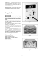
1
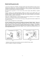
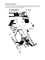
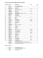
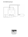
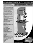
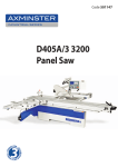
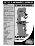
This .pdf document is bookmarked
Operating Instructions and Parts Manual
AFS-1000B Air Filtration System
JET
427 New Sanford Road
LaVergne, Tennessee 37086
Ph.: 800-274-6848
www.jettools.com
Part No. M-708620B
Revision B2 05/2014
Copyright © 2014 JET
Warranty and Service
®
JET warrants every product it sells against manufacturers’ defects. If one of our tools needs service or repair, please
contact Technical Service by calling 1-800-274-6846, 8AM to 5PM CST, Monday through Friday.
Warranty Period
The general warranty lasts for the time period specified in the literature included with your product or on the official
JET branded website.
•
JET products carry a limited warranty which varies in duration based upon the product. (See chart below)
•
Accessories carry a limited warranty of one year from the date of receipt.
•
Consumable items are defined as expendable parts or accessories expected to become inoperable within a
reasonable amount of use and are covered by a 90 day limited warranty against manufacturer’s defects.
Who is Covered
This warranty covers only the initial purchaser of the product from the date of delivery.
What is Covered
This warranty covers any defects in workmanship or materials subject to the limitations stated below. This warranty
does not cover failures due directly or indirectly to misuse, abuse, negligence or accidents, normal wear-and-tear,
improper repair, alterations or lack of maintenance.
Warranty Limitations
Woodworking products with a Five Year Warranty that are used for commercial or industrial purposes default to a
Two Year Warranty. Please contact Technical Service at 1-800-274-6846 for further clarification.
How to Get Technical Support
Please contact Technical Service by calling 1-800-274-6846. Please note that you will be asked to provide proof
of initial purchase when calling. If a product requires further inspection, the Technical Service representative will
explain and assist with any additional action needed. JET has Authorized Service Centers located throughout the
United States. For the name of an Authorized Service Center in your area call 1-800-274-6846 or use the Service
Center Locator on the JET website.
More Information
JET is constantly adding new products. For complete, up-to-date product information, check with your local distributor
or visit the JET website.
How State Law Applies
This warranty gives you specific legal rights, subject to applicable state law.
Limitations on This Warranty
JET LIMITS ALL IMPLIED WARRANTIES TO THE PERIOD OF THE LIMITED WARRANTY FOR EACH PRODUCT.
EXCEPT AS STATED HEREIN, ANY IMPLIED WARRANTIES OF MERCHANTABILITY AND FITNESS FOR A
PARTICULAR PURPOSE ARE EXCLUDED. SOME STATES DO NOT ALLOW LIMITATIONS ON HOW LONG AN
IMPLIED WARRANTY LASTS, SO THE ABOVE LIMITATION MAY NOT APPLY TO YOU.
JET SHALL IN NO EVENT BE LIABLE FOR DEATH, INJURIES TO PERSONS OR PROPERTY, OR FOR
INCIDENTAL, CONTINGENT, SPECIAL, OR CONSEQUENTIAL DAMAGES ARISING FROM THE USE OF OUR
PRODUCTS. SOME STATES DO NOT ALLOW THE EXCLUSION OR LIMITATION OF INCIDENTAL OR
CONSEQUENTIAL DAMAGES, SO THE ABOVE LIMITATION OR EXCLUSION MAY NOT APPLY TO YOU.
JET sells through distributors only. The specifications listed in JET printed materials and on official JET website are
given as general information and are not binding. JET reserves the right to effect at any time, without prior notice,
those alterations to parts, fittings, and accessory equipment which they may deem necessary for any reason
®
whatsoever. JET branded products are not sold in Canada by JPW Industries, Inc.
Product Listing with Warranty Period
90 Days – Parts; Consumable items; Light-Duty Air Tools
1 Year – Motors; Machine Accessories; Heavy-Duty Air Tools; Pro-Duty Air Tools
2 Year – Metalworking Machinery; Electric Hoists, Electric Hoist Accessories
5 Year – Woodworking Machinery
Limited Lifetime – JET Parallel clamps; VOLT Series Electric Hoists; Manual Hoists; Manual Hoist
Accessories; Shop Tools; Warehouse & Dock products; Hand Tools
NOTE: JET is a division of JPW Industries, Inc. References in this document to JET also apply to JPW Industries,
Inc., or any of its successors in interest to the JET brand.
2
Table of Contents
Warranty and Service ............................................................................................................................................ 2 Table of Contents .................................................................................................................................................. 3 Electrical Requirements ........................................................................................................................................ 5 Specifications ........................................................................................................................................................ 6 For Your Own Safety............................................................................................................................................. 6 Contents of Shipping Carton ............................................................................................................................. 7 Tools Required for Assembly ............................................................................................................................ 7 Assembly ........................................................................................................................................................... 7 Controls and Features ....................................................................................................................................... 8 Changing the Filters .......................................................................................................................................... 9 Replacement Parts.............................................................................................................................................. 10 Parts List for the AFS-1000B Air Filtration System ......................................................................................... 11 AFS-1000B Wiring Diagram ................................................................................................................................ 12 3
1. FOR YOUR OWN SAFETY, READ
INSTRUCTION MANUAL BEFORE
OPERATING THE TOOL. Learn the tool’s
application and limitations as well as the
specific hazards peculiar to it.
2. KEEP GUARDS IN PLACE and in working
order.
3. ALWAYS WEAR EYE PROTECTION.
4. GROUND ALL TOOLS. If tool is equipped
with three prong plug, it should be plugged
into a three-hole electrical receptacle. If an
adapter is used to accommodate a two
prong receptacle, the adapter lug must be
attached to a known ground. Never remove
the third prong.
5. KEEP WORK AREA CLEAN. Cluttered
areas and benches invite accidents.
6. DON’T USE IN DANGEROUS
ENVIRONMENT. Don’t use power tools in
damp or wet locations, or expose them to
rain. Keep work area well-lighted.
7. KEEP CHILDREN AND VISITORS AWAY.
All children and visitors should be kept a
safe distance from work area.
8. MAKE WORKSHOP CHILDPROOF. Use
padlocks, master switches, or remove
starter keys.
9. DON’T FORCE TOOL. It will do the job
better and be safer at the rate for which it
was designed.
10. USE RIGHT TOOL. Don’t force tool or
attachment to do a job for which it was not
designed.
11. WEAR PROPER APPAREL. No loose
clothing, gloves, neckties, rings, bracelets,
or other jewelry to get caught in moving
parts. Nonslip footwear is recommended.
Wear protective hair covering to contain long
hair.
12. ALWAYS USE SAFETY GLASSES. Wear
safety glasses (must comply with ANSI
Z87.1). Everyday eyeglasses only have
impact resistant lenses; they are not safety
glasses. Also use face or dust mask if
cutting operation is dusty.
13. SECURE WORK. Use clamps or a vise to
hold work when practical. It’s safer than
using your hands and frees both hands to
operate tool.
14. DON’T OVERREACH. Keep proper footing
and balance at all times.
15. MAINTAIN TOOLS IN TOP CONDITION.
Keep tools sharp and clean for best and
safest performance. Follow instructions for
lubricating and changing accessories.
16. DISCONNECT TOOLS before servicing
and when filters.
17. USE RECOMMENDED ACCESSORIES.
The use of accessories and attachments not
recommended by manufacturer may cause
hazards or risk of injury to persons.
18. AVOID ACCIDENTAL STARTING. Make
sure switch is in “OFF” position before
plugging in power cord.
19. NEVER STAND ON TOOL. Serious injury
could occur if the tool is tipped or if the fan
blade is accidentally contacted.
20. CHECK DAMAGED PARTS. Before further
use of the tool, a guard or other part that is
damaged should be carefully checked to
ensure that it will operate properly and
perform its intended function-check for
alignment of moving parts, binding of
moving parts, breakage of parts, mounting,
and any other conditions that may affect its
operation. A guard or other part that is
damaged should be properly repaired or
replaced.
21. NEVER LEAVE TOOL RUNNING
UNATTENDED. TURN POWER OFF.
Don’t leave tool until it comes to a complete
stop.
22. DRUGS, ALCOHOL, MEDICATION. Do not
operate tool while under the influence of
drugs, alcohol or any medication.
23. MAKE SURE TOOL IS DICONNECTED
FROM POWER SUPPLY while motor is
being mounted, connected or reconnected
24. WARNING: Some dust created by power
sanding, sawing, grinding, drilling and other
construction activities contains chemicals
known to cause cancer, birth defects or
other reproductive harm. Some examples of
these chemicals are:
• Lead from lead based paint
• Crystalline silica from bricks and
cement and other masonry products,
and
• Arsenic and chromium from chemicallytreated lumber.
Your risk from those exposures varies,
depending on how often you do this type of
work. To reduce your exposure to these
chemicals: work in a well ventilated area,
and work with approved safety equipment,
such as those dust masks that are
specifically designed to filter out microscopic
particles.
Electrical Requirements
In the event of a malfunction or breakdown, grounding provides a path of least resistance for electric current to
reduce the risk of electric shock. This tool is equipped with an electric cord having an equipment-grounding
conductor and a grounding plug. The plug must be plugged into a matching outlet that is properly installed and
grounded in accordance with all local codes and ordinances.
Do not modify the plug provided. If it will not fit the outlet, have the proper outlet installed by a qualified
electrician.
Improper connection of the equipment-grounding conductor can result in a risk of electric shock. The
conductor, with insulation having an outer surface that is green with or without yellow stripes, is the equipmentgrounding conductor. If repair or replacement of the electric cord or plug is necessary, do not connect the
equipment-grounding conductor to a live terminal.
Check with a qualified electrician or service personnel if the grounding instructions are not completely
understood, or if in doubt as to whether the tool is properly grounded.
Use only three wire extension cords that have three-prong grounding plugs and three-pole receptacles that
accept the tool’s plug.*
Repair or replace a damaged or worn cord immediately.
This tool is intended for use on a circuit that has an outlet that looks the one illustrated in Figure A below. The
tool has a grounding plug that looks like the grounding plug as illustrated in Figure A below. A temporary
adapter, which locks like the adapter as illustrated in Figures B below, may be used to connect this plug to a
two-pole receptacle, as shown in Figure B if a properly grounded outlet is not available.** The temporary
adapter should only be used until a properly grounded outlet can be installed by a qualified electrician. The
green colored rigid ear or tab, extending from the adapter, must be connected to a permanent ground such as
a properly grounded outlet box.
* Canadian electrical codes require extension cords to be certified SJT type or better.
** Use of an adapter in Canada is not acceptable.
5
Specifications
Model Number ...................................................................................................................................... AFS-1000B
Stock Number ........................................................................................................................................... 708620B
Outer Filter .............................................................................................................................................. 5 Microns
Inner Filter ................................................................................................................................................. 1 Micron
Overall Dimensions (LxWxH/in) ........................................................................................ 30-1/4 x 24-1/8 x 12-1/8
Sound Rating @ 3ft .................................................................................................................... High Speed 69 dB
............................................................................................................................................. Medium Speed 67 dB
.................................................................................................................................................... Low Speed 62 dB
Air Flow .............................................................................................................................. High Speed 1044 CFM
........................................................................................................................................ Medium Speed 702 CFM
.............................................................................................................................................. Low Speed 556 CFM
Filter Cycle (min.) ............................................................................................................................................. 3.06
Cycles per Hour (20’x20’x8’) .......................................................................................................................... 19.58
Motor ............................................................................................................. 1/5 HP, 115V, 60Hz, 1 PH, 6P, 4.5A
Net Weight ................................................................................................................................................... 54 lbs.
Shipping Weight ........................................................................................................................................... 61 lbs.
For Your Own Safety
1. Read and understand instruction manual before installing or operating air cleaner.
2. To reduce the risk of injury disconnect the air cleaner from the power source (unplug) before servicing
or changing filters.
3. If ceiling mounted, bottom of air cleaner must be at least 7 feet above the floor.
4. If ceiling mounted, mounts must be anchored to building structure which will support a minimum of at
least 100 pounds. Never mount to surfaces such as dry wall or false ceiling grids, etc.
5. To reduce the risk of electrical shock, do not expose air cleaner to water or rain.
6. Never duct a machine directly into the air cleaner.
7. To avoid a potentially dangerous situation, do not use this equipment to filter flammable vapors or
smoke. This air cleaner is designed and intended for the filtration of air borne wood dust only. It is
neither designed nor intended for any other purpose whatsoever.
8. Failure to comply may result in serious injury and / or property damage.
The above specifications were current at the time this manual was published, but because of our policy of
continuous improvement, JET reserves the right to change specifications at any time and without prior notice,
without incurring obligations.
6
Contents of Shipping Carton
1
1
3
4
4
8
8
4
1
1
Air Filtration Unit
Remote Control
AAA Batteries
Eye Bolts and Nuts
Mounting Brackets
Hex Cap Screws
Lock Washers
Foam Pads
Velcro Pad
Manual and Warranty Card
Tools Required for Assembly
No. 2 Cross Point Screwdriver
10mm Wrench
• The air filtration unit does not require much
assembly. You should take into consideration
how and where you will place this unit.
• It can be mounted horizontally and vertically.
The unit can also be hung from the ceiling.
• This unit will work best if it is located away from
corners, and heating/cooling vents.
• If using on sawhorses the air filtration unit should
be clamped in place.
• This unit is specifically designed to circulate and
filter non-metallic dust, which is generated
throughout the work area.
Assembly
Mounts must be anchored to
building structure, which will support a
minimum of at least 100 pounds. Never mount
to surfaces such as dry wall, false ceiling grids,
etc.
1.
Remove all packing from inside of the unit by
removing the outer filter and inner filters.
2.
The air filtration unit can be hung from the
ceiling. Remove four screws from the cabinet
top (A, Fig. 1).
3.
Hang the unit using four eyebolts (B, Fig. 1),
and four hex nuts (C, Fig. 1) provided.
Figure 1
4.
The lock nut needs to be threaded almost all
the way up the eyebolt. Screw the eye bolt into
the hole and tighten lock nut against the
cabinet top. You will need to hold the eyebolt
so it does not spin while tightening the lock
nut.
5.
Repeat steps for remaining three eyebolts.
Note: Make sure chain and ceiling hooks are
properly rated for hanging this unit. Hang unit with
a seven-foot clearance from the floor.
Figure 3 shows the mounting hole centers.
Figure 2
Mounts must be anchored to
building structure, which will support a
minimum of at least 100 pounds. Never mount
to surfaces such as dry wall or false ceiling
grids, etc.
Four brackets can also be used for mounting to the
ceiling, or wall:
1.
Place one end of bracket underneath the lip of
the cabinet.
2.
Attach the bracket (A, Fig. 2) with two hex cap
screws (B, Fig. 2) and two lock washers (C,
Fig. 2).
3.
Repeat steps for remaining three brackets.
4.
Peel off the paper backing from the foam
pads, and stick the pads to the bottom side of
the machine’s four corners.
Figure 3
Controls and Features
Remote Control:
Time button (A, Fig. 4) controls the three different
settings.
2H will light up on the back of the unit with one
press of the time button. The air filtration system
will operate for 2 hours then shut off.
4H will light up on the back of the unit by pressing
the time button twice. The air filtration system will
operate for 4 hours then shut off.
8H will light up on the back of the unit by pressing
the time button three times. The air filtration
system will operate for 8 hours then shut off.
Figure 4
Speed button (B, Fig. 4) controls the three different
settings, Low, Medium and High. There is also a
manual button (A, Fig. 5) on the backside of this
unit which controls the speed.
8
On/Off button (C, Fig. 4) turns the unit on and off.
There is also a manual on/off button (B, Fig. 5) on
the backside of the unit. Pressing this button will
turn the machine on Low.
Fuse switch (C, Fig. 5) will pop out in the case of
overload. Wait 3-5 minutes and push the fuse in.
Changing the Filters
To reduce the risk of injury,
disconnect the air cleaner from the power
source (unplug) before servicing or changing
filters. Failure to comply may cause serious
injury!
There are two filters that need to be changed. The
outer filter can easily be removed by disengaging
the two clips (A, Fig. 7).
Figure 5
Now you can simply pull the filter out, or use a
screwdriver to pop the filter out.
The inner filter (A, Fig. 7) can now be pulled out of
the unit. The inner filter can be blown out with
compressed air.
The filters should be replaced depending on the
amount of usage and the environment of your
shop. Clogged filters will reduce the amount of air
circulation. There is an arrow indicating the air
flow direction on the outer filter. Make sure the
filter is inserted facing the proper direction.
Replacement Filters
Figure 6
708731 electrostatic outer filter
708732 washable electrostatic outer filter
708733 inner filter
708734 charcoal filter
Figure 7
9
Replacement Parts
To order parts or reach our service department, call 1-800-274-6848, Monday through Friday (see our website
for business hours, www.jettools.com). Having the Model Number and Serial Number of your machine available
when you call will allow us to serve you quickly and accurately.
Parts List for the AFS-1000B Air Filtration System
Index No. Part No.
Description
Size
Qty
1 ................ 708731 ...................... Electrostatic Outer Filter .......................................... ...................................... 1
2 ................ 708733 ...................... Inner Three-Pocket Filter ......................................... ...................................... 1
4 ................ AB001008 ................. Door Clip Set ........................................................... ...................................... 2
5 ................ AB001108W .............. Air Box ..................................................................... ...................................... 1
6 ................ SJ069300 .................. Pan Head Bolt.......................................................... M6x12 ........................... 6
7 ................ OO1033..................... Switch Wire w/Terminal ........................................... ...................................... 1
8 ................ NH050800 ................. Nut ........................................................................... M5 ................................. 2
9 ................ WE050000 ................ Star Washer ............................................................. M5 ................................. 2
10 .............. OO1022W ................. Switch Plate ............................................................. ...................................... 1
.................. AB001022W .............. Switch Plate Set (assembly not shown)................... ........................................
11 .............. SP059300 ................. Pan Head Bolt.......................................................... M5x12 ........................... 1
12 .............. IC001015................... Electric Wire............................................................. ...................................... 1
13 .............. 998623 ...................... Strain Relief ............................................................. ...................................... 1
14 .............. 330075 ...................... 5A Thermos Switch.................................................. ...................................... 1
15 .............. 10042 ........................ Nut ........................................................................... M6 ................................. 4
16 .............. 330006 ...................... Sleeve ...................................................................... ...................................... 4
17 .............. 330005 ...................... Spacer ..................................................................... ...................................... 4
20 .............. WF061310................. Flat Washer ............................................................. M6 ................................. 6
21 .............. ST049200.................. Tapping Screw ......................................................... M4x8 ............................. 2
22 .............. SR089400 ................. Hex Socket Bolt ....................................................... M8x16 ........................... 1
23 .............. OO1055..................... Fan Blade ................................................................ ...................................... 1
24 .............. OO1056..................... Fan Housing ............................................................ ...................................... 1
25 .............. OO1057..................... Motor........................................................................ ...................................... 1
.................. CA001000B ............... Capacitor (not shown).............................................. ...................................... 1
26 .............. NF050800 ................. Nut ........................................................................... M5 ................................. 4
28 .............. 708711 ...................... Remote Control........................................................ ...................................... 1
29 .............. 330004 ...................... Flange ...................................................................... ...................................... 1
30 .............. 330043 ...................... PC Board ................................................................. ...................................... 1
31 .............. OO1023..................... Eye Bolt ................................................................... ...................................... 4
32 .............. NH061000 ................. Nut ........................................................................... M6 ................................. 4
33 .............. SN490200 ................. Counter Sunk Bolt.................................................... 1/8”x1/4” ........................ 3
34 .............. SP049100 ................. Pan Head Bolt.......................................................... M4x6 ............................. 4
35 .............. OO1029..................... Concave Handle ...................................................... ...................................... 2
36 .............. SR060600 ................. Hex Socket Bolt ....................................................... M6x30 ........................... 4
37 .............. WF061620................. Washer .................................................................... M6x16 ........................... 8
38 .............. LM000513 ................. I.D. Label ................................................................. ...................................... 1
39 .............. LM000344 ................. Remote Label .......................................................... ...................................... 1
40 .............. 990638 ...................... Wiring Nut ................................................................ P2.................................. 1
41 .............. SF069200.................. Rivet Nut .................................................................. M6x8 ............................. 4
42 .............. 330074 ...................... Pad .......................................................................... ...................................... 4
43 .............. TS-1551041 .............. Spring Washer ......................................................... M6 ................................. 6
44 .............. OO1027..................... Hanger Plate ............................................................ ...................................... 4
45 .............. SH069200 ................. Hex Head Bolt.......................................................... M6x8 ............................. 8
46 .............. TS-1551041 .............. Spring Washer ......................................................... M6 ................................. 8
.................. OO1045..................... Color Stripe (not shown) .......................................... ...................................... 1
.................. AH001103 ................. Hardware Kit (includes index # 28,31,32,37,42) ...... ...................................... 1
.................. LM000280 ................. JET Air Filtration I.D. Label (not shown: side of cabinet) ................................ 2
.................. LM000210 ................. Warning Label (not shown) ...................................... ...................................... 1
Replacement Filters:
.................. 708731 ...................... Electrostatic Outer Filter
.................. 708732 ...................... Washable Electrostatic Outer Filter
.................. 708733 ...................... Inner Three-Pocket Filter
.................. 708734 ...................... Charcoal Filter
11
AFS-1000B Wiring Diagram
427 New Sanford Road
LaVergne, Tennessee 37086
Phone: 800-274-6848
www.jettools.com
12