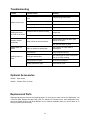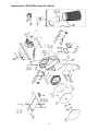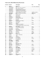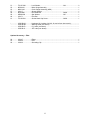
1
This .pdf document is bookmarked
Operating Instructions and Parts Manual
Benchtop 12-inch Disc Sander
Model JDS-12B
(708432K shown with optional stand 708438 and Canister Filter 708434)
WALTER MEIER (Manufacturing) Inc.
427 New Sanford Road
LaVergne, Tennessee 37086
Ph.: 800-274-6848
www.waltermeier.com
Part No. M-708433
Revision G 01/2010
Copyright © 2010 Walter Meier (Manufacturing) Inc.
Warranty and Service
Walter Meier (Manufacturing) Inc., warrants every product it sells. If one of our tools needs service or repair, one of
our Authorized Service Centers located throughout the United States can give you quick service. In most cases, any
of these Walter Meier Authorized Service Centers can authorize warranty repair, assist you in obtaining parts, or
perform routine maintenance and major repair on your JET ® tools. For the name of an Authorized Service Center in
your area call 1-800-274-6848.
MORE INFORMATION
Walter Meier is consistently adding new products to the line. For complete, up-to-date product information, check with
your local Walter Meier distributor, or visit waltermeier.com.
WARRANTY
JET products carry a limited warranty which varies in duration based upon the product (MW = Metalworking, WW =
Woodworking).
WHAT IS COVERED?
This warranty covers any defects in workmanship or materials subject to the exceptions stated below. Cutting tools,
abrasives and other consumables are excluded from warranty coverage.
WHO IS COVERED?
This warranty covers only the initial purchaser of the product.
WHAT IS THE PERIOD OF COVERAGE?
The general JET warranty lasts for the time period specified in the product literature of each product.
WHAT IS NOT COVERED?
Five Year Warranties do not cover woodworking (WW) products used for commercial, industrial or educational
purposes. Woodworking products with Five Year Warranties that are used for commercial, industrial or education
purposes revert to a One Year Warranty. This warranty does not cover defects due directly or indirectly to misuse,
abuse, negligence or accidents, normal wear-and-tear, improper repair or alterations, or lack of maintenance.
HOW TO GET SERVICE
The product or part must be returned for examination, postage prepaid, to a location designated by us. For the name
of the location nearest you, please call 1-800-274-6848.
You must provide proof of initial purchase date and an explanation of the complaint must accompany the
merchandise. If our inspection discloses a defect, we will repair or replace the product, or refund the purchase price,
at our option. We will return the repaired product or replacement at our expense unless it is determined by us that
there is no defect, or that the defect resulted from causes not within the scope of our warranty in which case we will,
at your direction, dispose of or return the product. In the event you choose to have the product returned, you will be
responsible for the shipping and handling costs of the return.
HOW STATE LAW APPLIES
This warranty gives you specific legal rights; you may also have other rights which vary from state to state.
LIMITATIONS ON THIS WARRANTY
WALTER MEIER (MANUFACTURING) INC., LIMITS ALL IMPLIED WARRANTIES TO THE PERIOD OF THE
LIMITED WARRANTY FOR EACH PRODUCT. EXCEPT AS STATED HEREIN, ANY IMPLIED WARRANTIES OR
MERCHANTABILITY AND FITNESS ARE EXCLUDED. SOME STATES DO NOT ALLOW LIMITATIONS ON HOW
LONG THE IMPLIED WARRANTY LASTS, SO THE ABOVE LIMITATION MAY NOT APPLY TO YOU.
WALTER MEIER SHALL IN NO EVENT BE LIABLE FOR DEATH, INJURIES TO PERSONS OR PROPERTY, OR
FOR INCIDENTAL, CONTINGENT, SPECIAL, OR CONSEQUENTIAL DAMAGES ARISING FROM THE USE OF
OUR PRODUCTS. SOME STATES DO NOT ALLOW THE EXCLUSION OR LIMITATION OF INCIDENTAL OR
CONSEQUENTIAL DAMAGES, SO THE ABOVE LIMITATION OR EXCLUSION MAY NOT APPLY TO YOU.
Walter Meier sells through distributors only. The specifications in Walter Meier catalogs are given as general
information and are not binding. Members of Walter Meier reserve the right to effect at any time, without prior notice,
those alterations to parts, fittings, and accessory equipment which they may deem necessary for any reason
whatsoever. JET ® branded products are not sold in Canada by Walter Meier.
2
Table of Contents
Warranty and Service..........................................................................................................................2
Table of Contents ...............................................................................................................................3
Warning .............................................................................................................................................4
Grounding Instructions ........................................................................................................................6
Introduction ........................................................................................................................................8
Specifications .....................................................................................................................................8
Unpacking ..........................................................................................................................................9
Contents of the Shipping Carton .......................................................................................................9
Assembly ......................................................................................................................................... 10
Stand Assembly (optional accessory) ............................................................................................. 10
Sander Assembly .......................................................................................................................... 10
Adjustments ..................................................................................................................................... 11
Table Adjustment .......................................................................................................................... 11
Sanding Disc Replacement ............................................................................................................ 11
Center Point .................................................................................................................................. 12
Filler Bar ....................................................................................................................................... 12
Brake............................................................................................................................................ 12
On/Off Switch................................................................................................................................ 12
Lubrication .................................................................................................................................... 12
Motor............................................................................................................................................ 12
Dust Collection .............................................................................................................................. 13
Canister Filter (optional accessory) ................................................................................................. 13
Cleaning the Filter ......................................................................................................................... 13
Optional Accessories ........................................................................................................................ 14
Replacement Parts ........................................................................................................................... 14
Breakdown for JDS-12B Benchtop Disc Sander .............................................................................. 15
Parts List for JDS-12B Benchtop Disc Sander ................................................................................. 16
Open Stand Assembly (Optional Accessory) ................................................................................... 18
Electrical Connections....................................................................................................................... 19
3
Warning
Wear eye protection.
Always keep guards in place and in proper operating condition. Do not operate the machine
without the guards for any reason.
This disc sander is intended to be used with wood and wood products only. Use of this disc
sander and a dust collector with metal products is a potential fire hazard.
Support the workpiece adequately at all times during operation; maintain control of the work
at all times.
This disc sander is designed and intended for use by properly trained and experienced personnel
only. If you are not familiar with the proper and safe operation of a disc sander, do not use until
proper training and knowledge has been obtained.
•
REMOVE ADJUSTING KEYS AND WRENCHES. Form a habit of checking to see that keys and
adjusting wrenches are removed from the machine before turning it on.
•
KEEP THE WORK AREA CLEAN. Cluttered areas and benches invite accidents.
•
DON’T USE IN A DANGEROUS ENVIRONMENT. Don’t use power tools in damp or wet locations,
or expose them to rain. Keep work area well lighted.
•
KEEP CHILDREN AWAY. All visitors should be kept a safe distance from the work area.
•
MAKE THE WORKSHOP KIDPROOF with padlocks, master swatches, or by removing starter keys.
•
DON’T FORCE THE MACHINE. It will do the job better and safer at the rate for which it was
designed.
•
USE THE RIGHT TOOL. Don’t force a machine or attachment to do a job for which it was not
designed.
•
USE THE PROPER EXTENSION CORD. Make sure your extension cord is in good condition. When
using an extension cord, be sure to use one heavy enough to carry the current your machine will
draw. An undersized cord will cause a drop in the line voltage resulting in power loss and
overheating. The table following shows the correct size to use depending on the cord length and
nameplate ampere rating. If in doubt, use the next heavier gauge. Remember, the smaller the gauge
number, the heavier the cord.
Volts
120V
25
16
Total Length of Cord in Feet
50
AWG
16
100
150
14
12
•
WEAR PROPER APPAREL. Do not wear loose clothing, gloves, neckties, rings, bracelets, or other
jewelry which may get caught in moving parts. Nonslip footwear is recommended. Wear protective
hair covering to contain long hair.
•
ALWAYS USE SAFETY GLASSES. Also use face or dust masks if the cutting operation is dusty.
Everyday eyeglasses only have impact resistant lenses; they are not safety glasses.
•
DON’T OVERREACH. Keep proper footing and balance at all times.
•
MAINTAIN TOOLS WITH CARE. Keep tools sharp and clean for best and safest performance.
Follow instructions for lubricating and changing accessories.
4
•
ALWAYS DISCONNECT THE MACHINE FROM THE POWER SOURCE BEFORE SERVICING.
•
REDUCE THE RISK OF UNINTENTIONAL STARTING. Make sure the switch is in the off position
before plugging in.
•
USE RECOMMENDED ACCESSORIES. The use of accessories and attachments not
recommended by JET may cause hazards or risk of injury to persons.
•
NEVER STAND ON A MACHINE. Serious injury could occur if the machine is tipped.
•
CHECK DAMAGED PARTS. Before further use of the machine, a guard or other part that is
damaged should be carefully checked to determine that it will operate properly and perform its
intended function - check for alignment of moving parts, binding of moving parts, breakage of parts,
mounting, and any other conditions that may affect its operation. A guard or other part that is
damaged should be properly repaired or replaced.
•
NEVER LEAVE THE MACHINE RUNNING UNATTENDED. TURN POWER OFF. Don’t leave the
machine until it comes to a complete stop.
•
SOME DUST CREATED by power sanding, sawing, grinding, drilling and other construction activities
contains chemicals known to cause cancer, birth defects or other reproductive harm. Some
examples of these chemicals are:
• Lead from lead based paint
• Crystalline silica from bricks and cement and other masonry products, and
• Arsenic and chromium from chemically-treated lumber.
Your risk from those exposures varies, depending on how often you do this type of work. To reduce
your exposure to these chemicals: work in a well ventilated area, and work with approved safety
equipment, such as those dust masks that are specifically designed to filter out microscopic particles
•
DO NOT operate tool while under the influence of drugs, alcohol or any medication.
•
AVOID kickback by sanding in accordance with directional arrows. Sand on downward side of disc.
Sanding on the upward side could cause the workpiece to fly up causing injury.
•
SAND with the grain of the wood.
•
DO NOT sand pieces of material that are too small to be safely supported.
•
WHEN sanding a large workpiece, provide additional support at table height.
•
ADDITIONAL INFORMATION regarding the safe and proper operation of this product is available
from the National Safety Council, 1121 Spring Lake Drive, Itasca, IL 60143-3201, in the Accident
Prevention Manual for Industrial Operations and also in the safety Data Sheets provided by the NSC.
Please also refer to the American National Standards Institute ANSI 01.1 Safety Requirements for
Woodworking Machinery and the U.S. Department of Labor OSHA 1910.213 Regulations.
•
SAVE THESE INSTRUCTIONS refer to them often and use them to instruct others.
Familiarize yourself with the following safety notices used in this manual:
This means that if precautions are not heeded, it may result in minor injury and/or
possible machine damage.
This means that if precautions are not heeded, it may result in serious or even fatal
injury.
5
Grounding Instructions
Warning: This tool must be grounded while in use to protect the operator from electric shock.
In the event of a malfunction or breakdown, grounding provides a path of least resistance for electric
current to reduce the risk of electric shock. This tool is equipped with an electric cord having an
equipment-grounding conductor and a grounding plug. The plug must be plugged into a matching outlet
that is properly installed and grounded in accordance with all local codes and ordinances.
Do not modify the plug provided. If it will not fit the outlet, have the proper outlet installed by a qualified
electrician.
Improper connection of the equipment-grounding conductor can result in a risk of electric shock. The
conductor, with insulation having an outer surface that is green with or without yellow stripes, is the
equipment-grounding conductor. If repair or replacement of the electric cord or plug is necessary, do not
connect the equipment-grounding conductor to a live terminal.
Check with a qualified electrician or service personnel if the grounding instructions are not completely
understood, or if in doubt as to whether the tool is properly grounded. Use only three wire extension
cords that have three-prong grounding plugs and three-pole receptacles that accept the tool’s plug.
Repair or replace a damaged or worn cord immediately.
115 Volt Operation
As received from the factory, your sander is ready to run at 115 volt operation. This sander, when wired
for 115 volt, is intended for use on a circuit that has an outlet and a plug that looks like the one illustrated
in (A). A temporary adapter, which looks like the adapter as illustrated in (B), may be used to connect
this plug to a two-pole receptacle, as shown in (B) if a properly grounded outlet is not available. The
temporary adapter should only be used until a properly grounded outlet can be installed by a qualified
electrician. This adapter is not applicable in Canada. The green colored rigid ear, lug, or tab,
extending from the adapter, must be connected to a permanent ground such as a properly grounded
outlet box, as shown in (B).
6
230 Volt Operation
If 230V, single phase operation is desired, the following instructions must be followed:
1. Disconnect the machine from the power source.
2. This JET sander is supplied with four motor leads that are connected for 115V operation, as shown in
Figure A. Reconnect these four motor leads for 230V operation, as shown in Figure B.
3. The 115V attachment plug (A), supplied with the sander, must be replaced with a UL/CSA listed plug
suitable for 230V operation (D). Contact your local Authorized JET Service Center or qualified
electrician for proper procedures to install the plug. The sander must comply with all local and
national codes after the 230 volt plug is installed.
4. The sander with a 230 volt plug should only be connected to an outlet having the same configuration
(D). No adapter is available or should be used with the 230 volt plug.
Important: In all cases (115 or 230 volts), make certain the receptacle in question is properly grounded.
If you are not sure, have a registered electrician check the receptacle.
7
Introduction
This manual is provided by Walter Meier (Manufacturing) Inc., covering the safe operation and
maintenance procedures for a JET Model JDS-12B Disc Sander. This manual contains instructions on
installation, safety precautions, general operating procedures, maintenance instructions and parts
breakdown. This machine has been designed and constructed to provide years of trouble free operation if
used in accordance with instructions set forth in this manual. If there are any questions or comments,
please contact either your local supplier or Walter Meier. Walter Meier can also be reached at our web
site: www.waltermeier.com.
Specifications
Model Number ........................................................................................................................ JDS-12B
Stock Number .......................................................................................................................... 708433
Disc Diameter (in.) ............................................................................................................................ 12
Table Tilt (deg.) ............................................................................................................. 15 up, 45 down
Dust Chute Diameter (in.) .................................................................................................................... 4
Disc Table (in.) .........................................................................................................16-3/8 W x 9-3/4 D
Motor ............................................................................................... TEFC, 1HP, 1PH, 115/230V, 60Hz
Impeller (in.) ................................................................................................................. 9 Dia. x 1-13/16
Overall Dimensions (in.) ..................................................................................... 21 W x 25-5/8 D x 21 H
Net Weight, approximate (lbs.)......................................................................................................... 100
The above specifications were current at the time this manual was published, but because of our policy of
continuous improvement, Walter Meier reserves the right to change specifications at any time and without
prior notice, without incurring obligations.
Read and understand the entire contents of this manual before attempting set-up
or operation! Failure to comply may cause serious injury.
8
Unpacking
Open shipping container and check for shipping
damage. Report any damage immediately to
your distributor and shipping agent. Do not
discard any shipping material until the Disc
Sander is assembled and running properly.
Compare the contents of your container with the
following parts list to make sure all parts are
intact. Missing parts, if any, should be reported
to your distributor. Read the instruction manual
thoroughly for assembly, maintenance and
safety instructions.
Contents of the Shipping Carton
JDS-12B Benchtop Sander
1
1
1
1
1
1
1
1
Sander
Sanding Disc
Table
Miter Gauge
Inlet
Inlet Gasket
Owner's Manual
Warranty Card
1
Hardware Kit
4 Hex Head Bolts M10x40
8 Flat Washers M10
4 Lock Washers M10
4 Hex Nuts M10
4 Hex Head Bolts M6x16
1 Center Point
1 Right Angle Hex Wrench 3mm
1 Filler Bar
1 Socket Head Cap Screw M5x8
(708432K shown with optional stand 708438
and Canister Filter 708434)
OS-12DS Stand (optional accessory)
4 Stand Legs
4 Stand Supports
Hardware Kit
16. Carriage Bolt M8x16
16. Hex Nut M8
CF-12DS Canister Filter (optional accessory)
1 Canister Filter
1 Plastic Elbow
1 Grounding Wire
Tools Required for Assembly &
Adjustments
1
1
13mm Wrench or socket
Combination Square
9
Assembly
Stand Assembly (optional accessory)
1. Match the hole patterns in the stand legs
with the hole patterns in the stand supports.
Mount the legs to the outside of the
supports using sixteen M8x16 carriage bolts
and sixteen M8 flange lock nuts, Figure 1.
Do not tighten until the stand has been
assembled and is sitting level on the floor.
2. Bolt the sander to the stand with four
M10x40 hex cap bolts, eight M10 flat
washers, four M10 lock washers and four
M10 hex nuts
Figure 1
Sander Assembly
1. Mount the sander to JET’s open stand with
four M10x40 hex head bolts, eight M10 flat
washers, four lock washers, and four hex
nuts. Tighten the nuts to secure the sander
to the stand.
2. Note: If you are going to use the sander as
a benchtop unit mount the sander to the
workbench with the supplied bolts.
3. Unscrew the knob (A, Figure 2), remove the
washer (B, Figure 2) and the trunnion holder
(C, Figure 2). Repeat for opposite side.
4. Lift the table (D, Figure 2) into position and
set on top of the split pins and threaded
shaft.
Figure 2
5. Reinstall the trunnion holder, washer and
knob. Repeat for opposite side.
6. Make sure the trunnion and trunnion holder
engage and tighten the knob.
7. Place the gasket (E, Figure 3) against the
sander base and mount the inlet port (F,
Figure 3) to the sander with four M6x16 hex
cap bolts (G, Figure 3).
Avoid kickback by sanding
in accordance with directional arrow. Sand
on downward side of disc. Sanding on the
upward side could cause the workpiece to fly
up causing injury! Failure to comply may
cause serious injury!
Figure 3
10
Adjustments
Table Adjustment
1. The table stops have been set-up at the
factory. However, if you run into a problem,
or want to check the table follow the below
listed steps.
2. Loosen lock knobs (B, Figure 4) and move
the table to the 90 degree position. Tighten
knobs and place a square (A, Figure 4)
against the table and disc. The square
should rest flat against the table and disc.
Figure 4
3. If adjustment is needed move the table so
that it rests 90 degrees from the table, and
loosen the hex nut (D, Figure 5) and tighten
the set screw (C, Figure 5) until it contacts
the table surface. Tighten hex nuts. This will
properly adjust the 90-degree stop.
4. Loosen the lock knobs (F, Figure 5) and tilt
the table up just enough to pivot the stop (E,
Figure 5) out of the way.
5. Tilt the table down until it hits the 45 degree
stop (G, Figure 5). Tighten lock knobs, and
check the table with a combination square.
6. If adjustment is needed, loosen the hex nut
(H, Figure 5) and adjust the socket head
cap screw (G, Figure 5) until it contacts the
table. Tighten hex nuts.
Figure 5
7. Always maintain a gap of approximately
1/16” between the table edge, and disc. If
adjustment is necessary loosen hex cap
bolts (I, Figure 5) and move the table into
position. Tighten hex cap bolts.
8. The table tilts between 15° up - 45° down by
loosening the lock knobs and tilting the table
to the desired angle. Tighten the knobs.
9. If you want to tilt the table up you need to
pivot the stop (E, Figure 5) out of the way.
Sanding Disc Replacement
1. Disconnect machine from the power
source.
2. Remove the knobs (J, Figure 6), washers
(K, Figure 6), and trunnion holders (L,
Figure 6) followed by the table assembly (M,
Figure 6).
3. Remove old sanding disc by striping from
wheel. Use a cleaner and putty knife to
remove the residue. Make sure the disc
plate is clean and dry.
4. Press the new disc firmly into place.
Figure 6
11
Center Point
The center point (A, Figure 7) provided with the
sander can be used for sanding circles. Slide
the center point into the miter slot that is
perpendicular to the sanding disc. The radius of
the desired circle should be the distance from
the center point to the sanding disc. Lock the
center point in position by tightening the set
screws. Cut the wood to the approximate
diameter and press on to the center point.
Rotate the wood until the desired results are
achieved.
Filler Bar
Figure 7
The filler bar (H, Figure 7) should be added
when sanding small workpieces. Secure in place
with the socket head cap screw (I, Figure 7).
When not using the filler bar thread the socket
head cap screw (I, Figure 7) in the tapped hole
as a stop.
Brake
After you have turned the sander “OFF” you can
press the brake (B, Figure 7) to slow, or stop the
sanding disc.
On/Off Switch
The machine can be turned “ON” by moving the
switch (D, Figure 8) to the “UP” position. The
key (E, Figure 8) can be removed when the
machine is in the “OFF” position. With the key
removed the switch will not operate.
Lubrication
You may need to lubricate the trunnion, and
trunnion holder (G, Figure 8) if the table does
not tilt smoothly.
Motor
Figure 8
Make frequent inspections of the motor fan cover,
and blow out (with low pressure air hose) or
vacuum any accumulation of foreign material in
order to maintain normal motor ventilation.
All electrical connections
must be done by a qualified electrician in
compliance with all relevant codes. All
adjustments or repairs must be done with
the sander disconnected from the power
source, unplugged. Failure to comply may
result in serious injury!
The JDS-12B disc sander is rated 115V/230V,
Prewired 115V.
12
If you want to run the JDS-12B on 230V refer to
the wiring diagram found on the inside of the
switch box cover (F, Figure 8).
Before hooking up to the power source, make
sure that the switch is in the off position.
It is recommended that the sander, when
operated at 115 volts, be connected to a
dedicated, minimum 20 amp circuit with a 20
amp circuit breaker or time delay fuse. When
operated at 230 volts, connect the sander to a
dedicated, minimum 10 amp circuit with 10 amp
circuit breaker or time delay fuse. Local codes
take precedence over recommendations.
Dust Collection
The disc sander has a built in fan designed to
suck the saw dust away from the sanding disc
and exhaust through the inlet (C, Figure 7). For
best results hook the sander to JET’s optional
accessory canister filter (#708434).
The sander can also be attached to a dust
collector using a 4” diameter hose and clamp.
JET offers a wide variety of hoses, adapters and
dust collectors.
Figure 9
Canister Filter (optional accessory)
1. Remove the inlet port that came with the
sander.
Cleaning the Filter
2. Mount the plastic elbow (A, Figure 9) to the
sander using the same hardware (B, Figure
9) from the inlet port.
Wearing
a
particle
mask/respirator for protection against fine
dust particles during cleaning is highly
recommended.
3. Connect the filter (C, Figure 9) to the elbow
and turn counter-clockwise so that it locks in
place.
Static electricity will build up
in the filter during operation. The filter
ground must be attached to the machine
ground, and to the filter. Failure to comply
may result in fire/loss of property, or
personal injury.
Clean the canister filter frequently to keep the
sander’s performance at its optimum. To clean:
1. Disconnect the machine from the power
source.
2. Take off the grounding clip and remove the
filter (C, Figure 9) by turning clockwise.
3. Empty the contents into an appropriate
container.
4. Remove the screw (D, Figure 9) from the
sander base. Attach the end of the
grounding wire to the screw and thread back
in to the base.
4. The filter can be cleaned with a low pressure
air hose. Blow from the outside of the filter to
clean the dust particles. For best results
check and empty the filter frequently.
5. Attach the grounding clip (E, Figure 9) to the
metal part of the filter. This will prevent static
electricity from building up in the filter.
5. Install the filter and reattach the grounding
clip.
13
Troubleshooting
Trouble
Probable Cause
Remedy
Sander unplugged from wall, or
motor.
Check all plug connections.
Fuse blown, or circuit breaker tripped.
Replace fuse, or reset circuit breaker.
Cord damaged.
Replace cord.
Starting capacitor not functioning.
Replace starting capacitor.
Extension cord too light or too long
Replace with adequate size and
length cord
Low current
Contact a qualified electrician
Machine vibrates
excessively
Stand or base on uneven surface
Adjust stand or base so that it rests
evenly on the floor
Sanded edge not
square
Table not square to sanding disc
Use a square to adjust table to
sanding disc
Work held still
Keep workpiece moving
Wrong grit sanding disc
Use coarser grit for stock removal and
fine grit for finish sanding
Feed pressure too great
Never force workpiece
Sanding against the grain
Sand with the grain
Sander will not start
Sanding disc does
not come up to speed
Sanding marks on
wood
Bolt down the base or stand
Optional Accessories
708438
Open Stand
708434
Canister Filter, 2 micron
Replacement Parts
Replacement parts are listed on the following pages. To order parts or reach our service department, call
1-800-274-6848, Monday through Friday (see our website for business hours, www.waltermeier.com).
Having the Model Number and Serial Number of your machine available when you call will allow us to
serve you quickly and accurately.
14
Breakdown for JDS-12B Benchtop Disc Sander
15
Parts List for JDS-12B Benchtop Disc Sander
Index No. Part No.
Description
Size
Qty
1 .............. 612131....................Guard Base ........................................................................................ 1
2 .............. MH612001 ..............Motor ...............................................................1 HP, 1Ph 110V/220V . 1
................ JDS12B-MFC ..........Motor Fan Cover (not shown) .............................................................. 1
................ JDS12B-MF.............Motor Fan (not shown) ........................................................................ 1
................ JDS12B-CS .............Centrifugal Switch (not shown) ............................................................ 1
................ JDS12B-CC.............Capacitor Cover (not shown) ............................................................... 1
................ JDS12B-JBC ...........Junction Box Cover (not shown) .......................................................... 1
................ JDS12B-SC .............Starting Capacitor (not shown)...........................200MFD, 125VAC.........
................ JDS12B-RC.............Running Capacitor (not shown)..........................10uF, 250V ..................
3 .............. KS050565 ...............Key ..................................................................5x5x65 ....................... 1
4 .............. 994534....................On/Off Switch ..................................................................................... 1
5 .............. 998621....................Strain Relief ....................................................................................... 1
6 .............. IC100001 ................Power Cord ........................................................................................ 1
7 .............. TS-1551071 ............Spring Washer..................................................M8 ............................. 4
8 .............. SJ080400 ................Pan Head Socket Bolt .......................................M8x20........................ 4
9 .............. 612132....................Fan Blade ........................................................9”............................... 1
10 ............ 612133....................Partition ............................................................................................. 1
11 ............ SF069200 ...............Pan Head Bolt w/Flange....................................M6x8 ......................... 5
12 ............ 612134....................Sanding Disc ...................................................................................... 1
13 ............ SS060200 ...............Set Screw ........................................................M6x8 ......................... 1
14 ............ 612113....................Washer .............................................................................................. 1
15 ............ SM089400...............Countersunk Head Bolt .....................................M8x16........................ 1
16 ............ ...............................12” Disc Sanding Paper (local purchase).............................................. 1
17 ............ 612136....................Front Cover ........................................................................................ 1
18 ............ SF069200 ...............Pan Head Bolt w/Flange....................................M6x8 ......................... 5
19 ............ TS-1504071 ............Socket Head Cap Screw ...................................M8x35........................ 1
20 ............ TS-1540061 ............Hex Nut............................................................M8 ............................. 1
21 ............ TS-1550061 ............Flat Washer......................................................M8x18........................ 1
22 ............ 612038....................Trunnion Holder (A) ............................................................................ 1
23 ............ PS062600 ...............Spring Pin ........................................................6x26 .......................... 4
24 ............ SS081200 ...............Set Screw ........................................................M8x60........................ 2
25 ............ TS-1550061 ............Flat Washer......................................................M8x18........................ 2
26 ............ 612098....................Knob ................................................................M8 ............................. 2
27 ............ 612052....................Trunnion Holder (B) ............................................................................ 1
28 ............ 612135....................Table ................................................................................................. 1
29 ............ 612046....................Trunnion ............................................................................................ 2
30 ............ TS-1551061 ............Lock Washer ....................................................M8 ............................. 4
31 ............ TS-1490021 ............Hex Head Bolt ..................................................M8x16........................ 4
32 ............ 612010....................Locating Block .................................................................................... 1
33 ............ PS053600 ...............Spring Pin ........................................................5x36 .......................... 1
34 ............ TS-1540041 ............Hex Nut............................................................M6 ............................. 1
35 ............ TS-1523071 ............Set Screw ........................................................M6x25........................ 1
36 ............ 612116....................Brake ................................................................................................. 1
37 ............ 612118....................Brake Fixed Base ............................................................................... 1
38 ............ PS042600 ...............Spring Pin ........................................................4x26 .......................... 1
39 ............ SP040200 ...............Pan Head Bolt ..................................................M4x10........................ 3
40 ............ 612140....................Spring ................................................................................................ 1
41 ............ WF051210 ..............Flat Washer......................................................M5x12........................ 1
42 ............ 612115....................Stop Handle ....................................................................................... 1
43 ............ TS-1491061 ............Hex Head Bolt * ................................................M10x40 ...................... 4
44 ............ TS-1550071 ............Flat Washer * ...................................................M10x20 ...................... 8
45 ............ TS-1551071 ............Lock Washer * ..................................................M10 ........................... 4
46 ............ TS-1540072 ............Hex Nut * .........................................................M10 ........................... 4
47 ............ 612137....................Packing .............................................................................................. 1
48 ............ 612145....................Inlet .................................................................4”............................... 1
49 ............ TS-1482031 ............Hex Head Bolt * ................................................M6x16........................ 4
50 ............ 612099....................Sponge .............................................................................................. 1
16
51 ............ TS-1551021 ............Lock Washer ....................................................M4 ............................. 2
52 ............ AB198101 ...............Miter Gauge Assembly ........................................................................ 1
53 ............ AB612143 ...............Circle Gauge Assembly (ASM) ............................................................ 1
57 ............ 612117....................Sponge Gasket................................................................................... 1
58 ............ SP059200 ...............Pan Head Bolt ..................................................M5x8 ......................... 1
59 ............ WE050000 ..............Star Washer .....................................................M5 ............................. 1
60 ............ 612171....................Filler Bar ............................................................................................ 1
61 ............ TS-1502011 ............Socket Head Cap Screw ...................................M5x8 ......................... 1
* .............. JDS12B-HK .............Hardware Kit (includes # 43-46, 49, and a 3mm hex wrench)...................
................ JDS12B-WL ............Warning Label (not shown) ....................................................................
................ JDS12B-ID ..............I.D. Label (not shown) ...........................................................................
................ JDS12B-JL ..............JET Label (not shown) ..........................................................................
Optional Accessory – Filter
54 ............ 612147....................Elbow................................................................................................. 1
55 ............ 331022....................Filter .................................................................................................. 1
56 ............ 331033....................Grounding Clip ................................................................................... 1
17
Open Stand Assembly (Optional Accessory)
Index No. Part No.
Description
Size
Qty
1 .............. 612141....................Stand Leg .......................................................................................... 4
2 .............. 612142....................Stand Support .................................................................................... 4
3 .............. SC089400 ...............Carriage Bolt ....................................................M8x16...................... 16
4 .............. NF081300 ...............Flange Lock Nut ...............................................M8 ........................... 16
* .............. OS12DS-HK ............Hardware Kit (not shown) ......................................................................
18
Electrical Connections
19
WALTER MEIER (Manufacturing) Inc.
427 New Sanford Road
LaVergne, Tennessee 37086
Phone: 800-274-6848
www.waltermeier.com
20