1
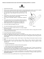
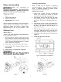
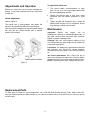
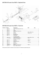
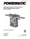
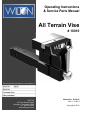
Operating Instructions
& Service Parts Manual
All Terrain Vise
# 10010
Record purchase information for quick reference:
WILTON
427 New Sanford Road
LaVergne, Tennessee 37086
Ph.: 800-274-6848
www.wiltontools.com
Manual No. M-10010
Rev A 11/2013
Copyright © 2013
Warranty and Service
JET, Wilton and Powermatic warrants every product they sell against manufacturers’ defects. If one of our tools needs service
or repair, please contact Technical Service by calling 1-800-274-6846, 8AM to 5PM CST, Monday through Friday.
Warranty Period
The general warranty lasts for the time period specified in the literature included with your product or on the official JET, Wilton
or Powermatic branded websites.
•
JET, Wilton and Powermatic products carry a limited warranty which varies in duration based upon the product. (See
chart below)
•
Accessories carry a limited warranty of one year from the date of receipt.
•
Consumable items are defined as expendable parts or accessories expected to become inoperable within a
reasonable amount of use and are covered by a 90 day limited warranty against manufacturer’s defects.
Who is Covered
This warranty covers only the initial purchaser of the product from the date of delivery.
What is Covered
This warranty covers any defects in workmanship or materials subject to the limitations stated below. This warranty does not
cover failures due directly or indirectly to misuse, abuse, negligence or accidents, normal wear-and-tear, improper repair,
alterations or lack of maintenance.
Warranty Limitations
Woodworking products with a Five Year Warranty that are used for commercial or industrial purposes default to a Two Year
Warranty. Please contact Technical Service at 1-800-274-6846 for further clarification.
How to Get Technical Support
Please contact Technical Service by calling 1-800-274-6846. Please note that you will be asked to provide proof of initial
purchase when calling. If a product requires further inspection, the Technical Service representative will explain and assist
with any additional action needed. JET, Wilton and Powermatic have Authorized Service Centers located throughout the
United States. For the name of an Authorized Service Center in your area call 1-800-274-6846 or use the Service Center
Locator on the JET, Wilton or Powermatic website.
More Information
JET, Wilton and Powermatic are consistently adding new products. For complete, up-to-date product information, check with
your local distributor or visit the JET, Wilton or Powermatic website.
How State Law Applies
This warranty gives you specific legal rights, subject to applicable state law.
Limitations on This Warranty
JET, WILTON AND POWERMATIC LIMIT ALL IMPLIED WARRANTIES TO THE PERIOD OF THE LIMITED WARRANTY
FOR EACH PRODUCT. EXCEPT AS STATED HEREIN, ANY IMPLIED WARRANTIES OF MERCHANTABILITY AND
FITNESS FOR A PARTICULAR PURPOSE ARE EXCLUDED. SOME STATES DO NOT ALLOW LIMITATIONS ON HOW
LONG AN IMPLIED WARRANTY LASTS, SO THE ABOVE LIMITATION MAY NOT APPLY TO YOU.
JET, WILTON AND POWERMATIC SHALL IN NO EVENT BE LIABLE FOR DEATH, INJURIES TO PERSONS OR
PROPERTY, OR FOR INCIDENTAL, CONTINGENT, SPECIAL, OR CONSEQUENTIAL DAMAGES ARISING FROM THE
USE OF OUR PRODUCTS. SOME STATES DO NOT ALLOW THE EXCLUSION OR LIMITATION OF INCIDENTAL OR
CONSEQUENTIAL DAMAGES, SO THE ABOVE LIMITATION OR EXCLUSION MAY NOT APPLY TO YOU.
JET, Wilton and Powermatic sell through distributors only. The specifications listed in JET, Wilton and Powermatic printed
materials and on official JET, Wilton and Powermatic-branded websites are given as general information and are not binding.
JET, Wilton and Powermatic reserve the right to effect at any time, without prior notice, those alterations to parts, fittings, and
®
accessory equipment which they may deem necessary for any reason whatsoever. JET branded products are not sold in
Canada by Walter Meier Manufacturing Americas.
Product Listing with Warranty Period
90 Days – Parts; Consumable items; Light-Duty Air Tools
1 Year – Motors; Machine Accessories; Heavy-Duty Air Tools; Pro-Duty Air Tools
2 Year – Metalworking Machinery; Electric Hoists, Electric Hoist Accessories
5 Year – Woodworking Machinery
Limited Lifetime – Wilton branded products; JET Parallel clamps; Manual Hoists; Manual Hoist Accessories;
Shop Tools; Warehouse & Dock products; Hand Tools
NOTE: JET, Wilton and Powermatic are divisions of Walter Meier Manufacturing Americas. References in this document to
JET, Wilton and/or Powermatic also apply to Walter Meier Manufacturing Americas or any of its successors in interest to the
JET, Wilton and/or Powermatic brands.
2
Read and understand the entire owner's manual before attempting installation or operation.
Warnings
1.
Keep hands clear of jaws.
2.
Make sure vise is properly secured to hitch receiver. If using accessory bench receiver, vise must be properly
secured within receiver, and receiver bolted to bench with appropriate fasteners (not included).
3.
Do not use the vise as a step; it may cause an individual to slip and
fall. This caution is also inscribed in the anvil of the vise – see
Figure 1.
4.
Keep ground or floor around the vise uncluttered and free of scrap
material, oil and grease. Wear non-slip footwear.
5.
Do not place combustible materials or pressurized containers in
vise.
6.
Do not force the tool. Do not use a hammer against the handle, or
use additional leverage such as cheater bars or pipe extensions, to
tighten the screw handle. For heavier jobs, use a larger vise.
7.
Vehicle safety brake must be engaged before operating vise.
8.
Do not drive vehicle with material in the vise.
9.
Use caution when backing a vehicle with the vise installed.
Figure 1
10. Make sure vise handle is locked and hitch pin is properly engaged
before driving vehicle.
11. Read and understand all warnings posted on the vise and in this manual. Failure to comply with all of these
warnings may cause serious injury.
12. Do not use this vise for other than its intended use.
13. Replace warning labels if they become obscured or removed.
14. Always wear ANSI-approved safety glasses or face shield when using striking or power tools with this vise.
(Everyday eyeglasses only have impact resistant lenses; they are not safety glasses.) Wear hearing protection
when needed.
15. Do not wear loose clothing or jewelry. Confine long hair. Keep clothing, hair and gloves away from moving
parts.
16. Some dust created by power sanding, sawing, grinding, drilling and other construction activities contain
chemicals known to cause cancer, birth defects or other reproductive harm. Some examples of these
chemicals are:
•
Lead from lead based paint.
•
Crystalline silica from bricks, cement and other masonry products.
•
Arsenic and chromium from chemically treated lumber.
Your risk of exposure varies, depending on how often you do this type of work. To reduce your exposure to
these chemicals, work in a well-ventilated area and work with approved safety equipment, such as face or dust
masks that are specifically designed to filter out microscopic particles.
17. Always inspect vise before use. Check for misalignment of moving parts, binding of moving parts, breakage of
parts, mounting and any other conditions that may affect the tool’s operation. If damage is found, repair the vise
immediately or replace it.
18. Have tool serviced only by qualified personnel, using authorized replacement parts.
3
19. Provide for adequate space surrounding work area and sufficient lighting.
20. Do not use this tool while tired or under the influence of drugs, alcohol or medication.
21. Keep bystanders, especially children, away from the area while using the vise.
22. Give your work undivided attention. Looking around, carrying on a conversation and “horse-play” are careless
acts that can result in serious injury.
23. Maintain a balanced stance at all times. Do not overreach while performing the work.
About this vise
The WILTON All Terrain Vise has been designed and constructed to provide consistent long-term operation,
if used in accordance with instructions as set forth in this document. The body is formed of high-strength
ductile cast iron. The leadscrew is precision ground carbon steel with acme threads. The tube has adjusting
screws top and side for eliminating play inside the hitch receiver. The handle can be repositioned without
moving the jaws.
About this manual
This manual covers operation and maintenance procedures for a WILTON All Terrain Vise. It contains
instructions on installation, safety precautions, general operating procedures, maintenance instructions and
parts breakdown.
The instructions and warnings presented in this manual cannot, of course, cover all possible situations or
conditions in which a vise may be used. The operator is expected to take appropriate precautions and
exercise common sense. As with any tool operation, safety of the operator and bystanders should be first
priority.
If there are questions or comments, please contact your local supplier or Wilton. Wilton can also be reached
at our web site: www.wiltontools.com.
Retain this manual for future reference. If the tool transfers ownership, the manual should accompany it.
Read and understand the entire contents of this manual before installing or using
the All Terrain Vise. Failure to comply may cause serious injury.
Specifications
Model .............................................................................................................................. WILTON All Terrain Vise
Stock number............................................................................................................................................... 10010
Required hitch receiver........................................................................................................................2 in. square
Jaw width ........................................................................................................................................ 150 mm (6 in.)
Maximum jaw opening .............................................................................................................. 145 mm (5-3/4 in.)
Jaw insert hardness............................................................................................................................. 45-56 HRC
Pipe capacity ..................................................................... 3/4 - 3 in. (or 1/2 - 3 in. with one jaw insert removed)
Clamping force................................................................................................................................................1 ton
Throat depth ................................................................................................................................... 127 mm (5 in.)
Jaw travel per one rotation of handle ............................................................................................ 4 mm (0.15 in.)
Weight........................................................................................................................................... 18 kg (39.68 lb)
Dimensions ....................................................................................... 489 x 150 x 185 mm (19-1/4 x 6 x 7-1/4 in.)
Primary materials.................................................................................................................. steel and ductile iron
Paint finish ............................................................................................................................. powder coat enamel
The specifications in this manual were current at time of publication, but because of our policy of continuous
improvement, Wilton reserves the right to change specifications at any time and without prior notice, without
incurring obligations.
4
Installing to bench/table
Setup and assembly
Bench or table must be capable of supporting
combined weight of vise, workpiece and applied
forces. If additional strength is needed, mount
supporting boards beneath the table.
Read
and
understand
all
instructions and warnings in this manual before
attempting installation or operation of hitch vise.
Failure to comply may cause serious injury.
Refer to Figures 3 and 4.
1. Position vise on bench. The rear (or static) jaw
should just overhang the bench to prevent
obstruction when inserting long work pieces.
Shipping contents
1
1
1
1
1
Vise
Hitch pin with cotter pin
Bench mount receiver
Instructions and parts manual
Warranty card
Remove contents from shipping carton, and check for
shipping damage or missing parts. If either of these is
discovered, contact your dealer or Walter Meier
(Manufacturing) Inc., at the phone number on the
cover.
2.
Place bench receiver over vise tube and mark
hole positions on bench. Figure 3 identifies hole
dimensions. Drill holes of appropriate diameter in
table.
3.
Mount bench receiver to bench using fasteners of
suitable grade, length and diameter. The hole in
the side of the receiver should be at the end
farthest from the vise.
4.
Slide vise tube into bench receiver. If there is too
much “play” within the receiver, rotate any of the
four adjustment screws on the tube (A, Figure 2).
5.
Install hitch pin through holes of tube and receiver
(Figure 4).
6.
Install cotter pin into hitch pin hole.
Installing to hitch
Refer to Figure 2.
The All Terrain Vise is designed to be inserted into a
2-inch square hitch receiver.
1. Slide vise tube into receiver. If there is too much
“play” within the receiver, remove the vise and
rotate any of four screws (A) on the vise tube, with
a 5/16” hex key. Reinstall and test for fit, making
further adjustments as needed.
2. Align hole in vise tube with hole in hitch receiver.
3. Insert hitch pin (B) completely through receiver
and vise tube.
4. Install cotter pin (C) through hole in hitch pin.
Cotter pin must be properly
secured in hitch pin before operating vise or
moving vehicle to which vise is mounted.
Figure 3 (dimensions in millimeters)
Figure 4
Figure 2
5
To operate the hitch vise:
Adjustments and Operation
1. Turn screw handle counterclockwise to open
jaws. Do not try to force jaws apart farther than
the rated capacity/jaw opening.
Before use, inspect the vise for cracks, misalignment,
binding, or any other problems that may compromise
its safe use.
2.
Choose the straight jaws or pipe jaws. Insert
workpiece and turn handle clockwise to close
jaws.
3.
Tighten enough that workpiece can no longer be
shifted within the jaws. Do not overtighten, as this
may damage workpiece and/or jaws.
Handle adjustment
Refer to Figure 5.
The handle hub is spring-loaded, and allows the
handle to be repositioned without moving the jaws.
Maintenance
After securing the workpiece in the jaws, grasp handle
hub and pull out. Rotate handle hub to desired
position, then release.
Inspection:
Before
use,
inspect vise
for
misalignment, binding or cracked/damaged parts, or
any other condition that may affect safe operation.
Repair or replace a damaged vise.
Cleaning: After use, wipe external surfaces of the
vise with a clean rag. Apply a light coat of machine oil
to exposed metal areas.
Lubrication: The leadscrew is permanently lubricated
and enclosed, and should not require attention.
Lubricate other moving parts of the vise with machine
oil.
Jaw insert replacement: Use a 5mm hex key to
remove two screws on the jaw insert. Securely tighten
the new jaw insert to the vise using the same screws.
NOTE: If replacing jaw inserts, replace both as a set.
Figure 5
Replacement Parts
To order parts or reach our service department, call 1-800-274-6848 Monday through Friday, 8AM to 5PM CST.
Having the Model Number and Serial Number of your machine available when you call will allow us to serve you quickly
and accurately.
6
WILTON All Terrain Vise #10010 – Exploded View
WILTON All Terrain Vise #10010 – Parts List
Index No Part No
Description
Size
Qty
..................... ATV-HA ................... Handle Assembly (index #1-5) ....................... .................................................... 1
1 ................... ATV-01 .................... Cap ............................................................... .................................................... 1
2 ................... ATV-02 .................... Handle ......................................................... .................................................... 1
3 ................... ATV-03 .................... Socket Head Cap Screw................................ .................................................... 1
4 ................... ATV-04 .................... Washer ......................................................... Ø11 x Ø20x 2 mm ........................ 1
5 ................... ATV-05 .................... Spring ........................................................... Ø16x22 mm ................................. 1
9 ................... ATV-09 .................... Set Screw...................................................... .................................................... 2
10 ................. ATV-10 .................... Spindle Collar ................................................ .................................................... 1
11 ................. ATV-11 .................... Lead Screw ................................................... .................................................... 1
12 ................. ................................ Floating Jaw Body ......................................... .................................................... 1
13 ................. ATV-13 .................... Jaw Insert (set of 2) ....................................... 6”L x 1/2"W x 7/8”H ................ 1 set
14 ................. TS-1503031 ............. Socket Head Cap Screw................................ M6x12.......................................... 4
15 ................. ................................ Stationary Jaw Body ...................................... .................................................... 1
16 ................. ATV-16 .................... Hitch Pin ....................................................... Ø16 mm ....................................... 1
17 ................. ATV-17 .................... Cotter Pin ...................................................... Ø4 mm......................................... 1
18 ................. ATV-17 .................... Adjustment Screw ......................................... .................................................... 4
19 ................. ATV-18 .................... Roll Pin ......................................................... 4x12 mm ...................................... 2
20 ................. ATV-19 .................... Spindle Nut ................................................... .................................................... 1
21 ................. ATV-20 .................... Spacer .......................................................... .................................................... 1
22 ................. JHM610-22 .............. Socket Head Cap Screw................................ M6x14.......................................... 1
23 ................. ATV-22 .................... Bench Mount Receiver .................................. .................................................... 1
Some parts are shown for reference only and may not be available as replacement parts.
7
427 New Sanford Road
LaVergne, Tennessee 37086
Phone: 800-274-6848
www.wiltontools.com
8