1
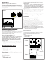
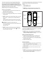
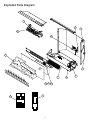
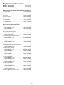
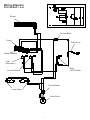
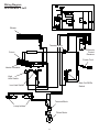
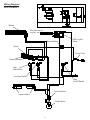
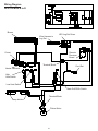
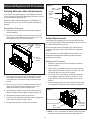
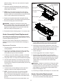
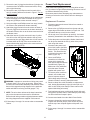
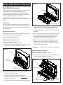
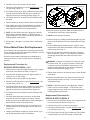
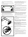
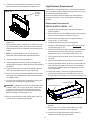
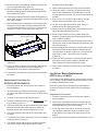
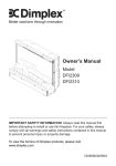
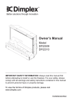
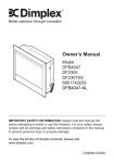
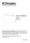
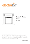
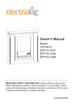
Service Manual
23” Insert
Model Numbers:
DFI2309 MOD ~ to D
DFI2310 MOD ~ to D
Rev
Dimplex North America Limited
1367 Industrial Road Cambridge ON Canada N1R 7G8
1-888-346-7539 www.dimplex.com
PCN
Date
00
n/a
10.2006
01
12226
08.2010
02
13569
09.2012
03
In keeping with our policy of continuous product development, we reserve the right to make changes without notice.
06.2013
7400070000R03
Table of Contents
Operation. . . . . . . . . . . . . . . . . . . . . . . . . . . . . . . . . . . . . . . . . . . . . . . . . . . . . . . . . . . . . . . . . . . . . . 3
Exploded Parts Diagram. . . . . . . . . . . . . . . . . . . . . . . . . . . . . . . . . . . . . . . . . . . . . . . . . . . . . . . . . . 5
Replacement Parts List. . . . . . . . . . . . . . . . . . . . . . . . . . . . . . . . . . . . . . . . . . . . . . . . . . . . . . . . . . . 6
Wiring Diagram . . . . . . . . . . . . . . . . . . . . . . . . . . . . . . . . . . . . . . . . . . . . . . . . . . . . . . . . . . . . . . . . . 7
DFI2309 MOD ~ to B. . . . . . . . . . . . . . . . . . . . . . . . . . . . . . . . . . . . . . . . . . . . . . . . . . . . . . . . . . . . . . . . . . . . . . 7
DFI2309 MOD C to D . . . . . . . . . . . . . . . . . . . . . . . . . . . . . . . . . . . . . . . . . . . . . . . . . . . . . . . . . . . . . . . . . . . . . 8
DFI2310 MOD ~ . . . . . . . . . . . . . . . . . . . . . . . . . . . . . . . . . . . . . . . . . . . . . . . . . . . . . . . . . . . . . . . . . . . . . . . . . 9
DFI2310 MOD A to D. . . . . . . . . . . . . . . . . . . . . . . . . . . . . . . . . . . . . . . . . . . . . . . . . . . . . . . . . . . . . . . . . . . . . 10
Universal Replacement Procedures . . . . . . . . . . . . . . . . . . . . . . . . . . . . . . . . . . . . . . . . . . . . . . . . 11
Partially reflective glass Replacement. . . . . . . . . . . . . . . . . . . . . . . . . . . . . . . . . . . . . . . . . . . . . . . . . . . . . . . . 11
Switch Replacement. . . . . . . . . . . . . . . . . . . . . . . . . . . . . . . . . . . . . . . . . . . . . . . . . . . . . . . . . . . . . . . . . . . . . 11
Heater Assembly/Cutout Replacement. . . . . . . . . . . . . . . . . . . . . . . . . . . . . . . . . . . . . . . . . . . . . . . . . . . . . . . 12
Heater Assembly Replacement. . . . . . . . . . . . . . . . . . . . . . . . . . . . . . . . . . . . . . . . . . . . . . . . . . . . . . . . . . . . . 12
Power Cord Replacement. . . . . . . . . . . . . . . . . . . . . . . . . . . . . . . . . . . . . . . . . . . . . . . . . . . . . . . . . . . . . . . . . 13
Model / MOD Specific Procedures. . . . . . . . . . . . . . . . . . . . . . . . . . . . . . . . . . . . . . . . . . . . . . . . . 14
Light Bulb Replacement . . . . . . . . . . . . . . . . . . . . . . . . . . . . . . . . . . . . . . . . . . . . . . . . . . . . . . . . . . . . . . . . . . 14
Flicker Motor/Flicker Rod Replacement . . . . . . . . . . . . . . . . . . . . . . . . . . . . . . . . . . . . . . . . . . . . . . . . . . . . . . 15
Remote Receiver Board Replacement . . . . . . . . . . . . . . . . . . . . . . . . . . . . . . . . . . . . . . . . . . . . . . . . . . . . . . . 16
Light Harness Replacement . . . . . . . . . . . . . . . . . . . . . . . . . . . . . . . . . . . . . . . . . . . . . . . . . . . . . . . . . . . . . . . 17
Log Driver Board Replacement. . . . . . . . . . . . . . . . . . . . . . . . . . . . . . . . . . . . . . . . . . . . . . . . . . . . . . . . . . . . . 18
Troubleshooting Guide. . . . . . . . . . . . . . . . . . . . . . . . . . . . . . . . . . . . . . . . . . . . . . . . . . . . . . . . . . 20
2
Operation
This three (3) position switch offers the following functions:
(I) Manual mode
When in the “ I ” position, the fireplace bypasses the builtin remote control, the flame effect is turned on and the
electrical supply to the heater is controlled manually using
the Low Heat and High Heat Switches (Figure 1-C and D).
Electric Fireplace Manual Control
The manual controls for the unit are located in the top, right
corner, on the front of the firebox (Figure 1). A switch is in
the On position when the side with the “ I ”, or “ II ” markings
on it is pushed in.
Figure 1
D
C
D
A
C
(II) Remote mode
The “ II ” position is for operating the unit with the provided
remote control. When in “ II ” position the unit is operated
with the ON and OFF buttons of the remote control.
B
! NOTE: Remote control operates main power supply. Heat
or
must still be controlled by switches on fireplace.
(O) Off position
All power to all functions are switched off.
Resetting the Temperature Cutoff Switch
Should the fireplace overheat, an automatic cut out will turn
the heater off and it will not come back on without being
reset. It can be reset by switching the Main Power Switch
(Figure 1-A or B) to the Off (“ O ”) position, and waiting five
(5) minutes before switching the unit back on.
CAUTION: If you need to continuously reset the heater,
unplug the unit and call Dimplex North America Limited at
1-888-346-7539 for technical support.
Heat Switches (all models, all MOD levels)
Figure 1-C - Low Heat Switch (“ I ”)
The Low Heat On/Off Switch supplies power to the heater fan
and the heater element. When the switch is in the On (“ I ”)
position the heater operates on Low.
Remote Controls
The following plug-in remote control (Figure 2) is included
with the models and MOD levels specified below:
Used in:
• DFI2309 MODs ~ to B
• DFI2310 MOD ~
Figure 1-D - High Heat Switch (“ II ”)
The High Heat Switch supplies power to the heater fan and
the heater element, when the switch is in the On (“ II ”)
position the heater operates on High. The C - Low Heat
Switch must also be in the On position for the high heat
setting to operate.
Figure 2
On button
! NOTE: If Switches C and D are in the Off position, only
the flame effect will turn on when the power switch is
activated.
Off button
Main Power Switches (Figure 1-A & B)
A - On/Off Switch
Used in:
• DFI2309 MODs ~ to B
• DFI2310 MOD ~
OPEN
Battery
cover
Frequency
The two (2) position On/Off Switch supplies power to all the
fireplace functions.
Plug-in
receiver
B - On/Off/On Switch
Used in:
• DFI2309 MODs C to D
• DFI2310 MODs A to D
3
Receiver outlet
The remote control has a range of approximately 50 feet
(15.25 m). It does not have to be pointed at the fireplace
and can pass through most obstacles (including walls). It is
supplied with one of 243 independent frequencies to prevent
interference with other units and the frequency designation is
indicated on the back of the remote control.
Replace battery when needed with a 9 volt battery.
The following integrated remote control (Figure 3) is included
with the models and MOD levels specified below:
Used in:
• DFI2309 MODs C to D
• DFI2310 MOD A2 to D
! NOTE: Ensure that the fireplace’s 3 Position On/Off
Switch (Figure 1-B) is set to the remote control (“ II ”)
Remote Control Installation
1. Plug fireplace power cord into the outlet located on the
side of the receiver (Figure 2).
2. Plug receiver into the wall outlet.
3. Remove the plastic tag at the battery cover, to activate the
remote control.
Figure 3
On
Button
! NOTE: Fireplace Power On/Off Switch (Figure 1-A) must
Battery
be in the On (“ I ”) position prior to using the Remote
Control.
Off
Button
ON/OFF Remote Control may be used to control most
other electrical devices including TV’s, stereos and lamps.
CAUTION: For indoor use in dry areas only.
For use on electrical devices with 15 amp resistive load or
1/3 HP inductive load.
120 volt AC only.
Battery Cover
setting.
! NOTE: The plug-in remote version may include either
the remote control as pictured on page 3 or the remote
control as shown to the right.
To operate: push ON button to turn fireplace on; push OFF
button to turn fireplace off (Figure 3).
! NOTE: Remote control operates main power supply.
Heat must still be controlled by Low Heat and High Heat
switches on fireplace (Figure 1-C & D).
Battery Installation/Replacement
1. Depress tab on the battery cover on the back of the
remote control and remove battery cover (Figure 3).
2. Properly orient and install one (1) 12 Volt (A23) battery
into the remote control.
3. Replace the battery cover.
Remote Initialization
1. From an power off position, place the 3-Position Switch
(Figure 1-B) into the Remote (“ II ”) position.
2. Within 10 seconds of step 1, press the ON button on the
remote control.
This will synchronize the remote control with the receiver
within the fireplace.
! NOTE: You will only have 10 seconds to perform the last
step. If this is not completed within 5-10 seconds, the
procedure will have to be repeated.
4
Exploded Parts Diagram
3
12
7
2
16
8
1
9
5
15 14 13
10
11
5
4
6
Replacement Parts List
DFI2309 - Part Number . . . . . . . . . . . . . . . . . . . 6901470159
DFI2310 - Part Number . . . . . . . . . . . . . . . . . . . 6901470259
Replacement Parts for both DFI2309, DFI2310 all MODs:
1. Power Cord. . . . . . . . . . . . . . . . . . . . . . . . 4100090101RP
2. Heater Assembly . . . . . . . . . . . . . . . . . . . 2200490800RP
3.Cutout . . . . . . . . . . . . . . . . . . . . . . . . . . . 2300270200RP
4. Flicker Motor . . . . . . . . . . . . . . . . . . . . . . . 2000220100RP
5. Flicker Rod. . . . . . . . . . . . . . . . . . . . . . . . . 5900340100RP
6.Lampholder. . . . . . . . . . . . . . . . . . . . . . . . 4200121000RP
7. Terminal block. . . . . . . . . . . . . . . . . . . . . . 4000070100RP
Non-Universal Replacement Parts
8. Log set
DFI2309 MOD ~ to C. . . . . . . . . . . . . . . . . 0438200200RP
DFI2309 MOD D . . . . . . . . . . . . . . . . . . . . 0438200800RP
DFI2310 MOD ~ to D. . . . . . . . . . . . . . . . . 0439230200RP
9. Partially reflective glass
DFI2309 all MODs . . . . . . . . . . . . . . . . . . 5900350100RP
DFI2310 all MODs . . . . . . . . . . . . . . . . . . 5900350200RP
10.2 Piece Plug-in Remote Control
DFI2309 MOD ~ to B. . . . . . . . . . . . . . . . 680024RPNEW
DFI2310 MOD ~ . . . . . . . . . . . . . . . . . . . 680024RPNEW
11.Integrated Remote Control
DFI2309 MOD C to D . . . . . . . . . . . . . . . . 3000370500RP
DFI2310 MOD A to D. . . . . . . . . . . . . . . . . 3000370500RP
12.Integrated Remote Control Receiver
DFI2309 MOD C to D . . . . . . . . . . . . . . . . 3000380200RP
DFI2310 MOD A to D. . . . . . . . . . . . . . . . . 3000380200RP
13.Main Power Switch
DFI2309 MOD ~ to A. . . . . . . . . . . . . . . . 2800090100RP*
DFI2309 MOD B . . . . . . . . . . . . . . . . . . . . 2800070700RP
DFI2309 MOD C to D . . . . . . . . . . . . . . . . 2800071100RP
DFI2310 MOD ~ . . . . . . . . . . . . . . . . . . . . 2800070700RP
DFI2310 MOD A to D. . . . . . . . . . . . . . . . . 2800071100RP
14. Low Heat Switch
DFI2309 MOD ~ to A. . . . . . . . . . . . . . . . 2800090100RP*
DFI2309 MOD B to D. . . . . . . . . . . . . . . . . 2800070900RP
DFI2310 MOD ~ . . . . . . . . . . . . . . . . . . . 2800090100RP*
DFI2310 MOD A to D. . . . . . . . . . . . . . . . . 2800070900RP
15.High Heat Switch
DFI2309 MOD ~ to A. . . . . . . . . . . . . . . . 2800090100RP*
DFI2309 MOD B to D. . . . . . . . . . . . . . . . . 2800071000RP
DFI2310 MOD ~ . . . . . . . . . . . . . . . . . . . 2800090100RP*
DFI2310 MOD A to D. . . . . . . . . . . . . . . . . 2800071000RP
16.LED Log Driver (DFI2310 only). . . . . . . . . 3000390100RP
6
Wiring Diagram
DFI2309 MOD ~ to B
Blower
Terminal Block
Cutout
Power Cord
Heater Elements
High
Heat Switch
Main
On/Off Switch
Low Heat Switch
Terminal Block
Lamp holders
Flicker Motor
7
Wiring Diagram
DFI2309 MOD C to D
Blower
Terminal Block
Remote
Control
Receiver
Cutout
Power Cord
Heater Elements
High
Heat Switch
Main On/Off/On
Switch
Low Heat Switch
Terminal Block
Lamp holders
Flicker Motor
8
Wiring Diagram
DFI2310 MOD ~
Blower
Wire Harness to
Log Set
Terminal Block
LED Log Set
Driver
Cutout
Power Cord
Heater Elements
High
Heat Switch
Low Heat Switch
Main
On/Off Switch
Terminal Block
Lamp holders
Flicker Motor
9
Wiring Diagram
DFI2310 MOD A to D
Blower
Wire Harness to
Log Set
LED Log Set Driver
Remote
Receiver
Board
Cutout
Terminal Block
Cord Set
Heater Elements
High
Heat Switch
Low Heat Switch
Main On/Off/On Switch
Terminal Block
Lamp holders
Flicker Motor
10
Universal Replacement Procedures
Figure 5
Switch
control panel
Partially
reflective
glass
Partially Reflective Glass Replacement
If the firebox was operating prior to servicing allow at least
five (5) minutes for light bulbs and heating element to cool off
to avoid accidental burning of skin.
Log set
Disconnect power before attempting any maintenance or
cleaning to reduce the risk of electric shock or damage to
persons.
Replacement Procedure
1. Disconnect power and remove firebox from mantel or
existing fireplace.
2. Remove four (4) Phillips screws from the top and rear,
upper edge of the firebox as shown in Figure 4-A. This
will release the top cover from the firebox.
Figure 4
Switch Replacement
If the firebox was operating prior to servicing allow at least
five (5) minutes for light bulbs and heating element to cool off
to avoid accidental burning of skin.
A. Step 2
screws to
remove
Disconnect power before attempting any maintenance or
cleaning to reduce the risk of electric shock or damage to
persons.
Each of the three (3) switches (Main Power Switch, Low
Heat Switch and High Heat Switch) will have the same
replacement procedure.
B. Step 3
screws to
remove
Replacement Procedure:
1. Disconnect power and remove firebox from mantel or
existing fireplace.
2. Remove four (4) Phillips screws from the top and rear,
upper edge of the firebox as shown in Figure 4-A. This
will release the top cover from the firebox.
3. Tilt the top cover of the firebox up and either prop the
cover against a stationary object or situate it in such
a way that there is access to the upper section of the
firebox.
3. Tilt the top cover of the firebox up and either prop the
cover against a stationary object or situate it in such
a way that there is access to the upper section of the
firebox.
4. Remove all wiring clips and connections from the switch
to be replaced, noting their original locations (Figure 6).
4. Remove one (1) or two (2) Phillips screws from each
upper corner of the firebox as shown in Figure 4-B.
Quantity will differ by model and MOD level.
Figure 6
5. Gently push the switch control panel inwards until top
edge of partially reflective glass is exposed (Figure 5).
Retainer clips
6. Slide partially reflective glass up to remove.
7. Properly orient replacement partially reflective glass and
slide it down into place behind Log Set.
High Heat switch
8. Re-assemble firebox in reverse order as above.
Low Heat switch
Main
power switch
Wire
connection
terminals
! NOTE: It may be necessary to remove all wire clips and/
or switches in order to provide sufficient working room
11
within the firebox. Be sure to note each wire’s original
location carefully.
Figure 7
5. Remove the switch by depressing the retaining clips
(Figure 6) and pushing the switch forward, through the
sheet metal of the firebox.
Step 5 screws to
remove (4)
Top cover
Mounting brackets
& screws
! NOTE: Due to the switches’ placement under the lip
of sheet metal, it may be necessary to use a large flatheaded screwdriver to slide between the switch and sheet
metal in order to depress the top retaining clip.
Heater elements
6. Properly orient replacement switch and push through
sheet metal of firebox until retaining clips snap into place.
Heater blower & motor
7. Re-connect wiring clips removed in step 5.
Figure 8
WARNING: Improper re-connection of wiring may
result in electric shock, fire, or injury to persons. Ensure
that connections to/from switches match those of the
respective wiring diagram for the particular model and
MOD level being serviced (pages 7-10).
Cutout screw
Blower motor
Heater
elements
9. Re-assemble firebox following steps 1-3 in reverse order.
Heater Assembly/Cutout Replacement
Terminal block
If the firebox was operating prior to servicing allow at least
five (5) minutes for light bulbs and heating element to cool off
to avoid accidental burning of skin.
Upper, inside
corner of firebox
Disconnect power before attempting any maintenance or
cleaning to reduce the risk of electric shock or damage to
persons.
a small Phillips screwdriver to loosen the screw which
clamps the wire from the cutout to the terminal block.
ii) With wires loose from their connections, remove the
small Phillips screw that attaches the cutout to the heater
assembly (Figure 8). Remove and discard old cutout.
Replacement Procedure
1. Disconnect power and remove firebox from mantel or
existing fireplace.
iii) Attach replacement cutout to heater assembly using
screw from step ii.
2. Remove four (4) Phillips screws from the top and rear,
upper edge of the firebox as shown in Figure 4-A. This
will release the top cover from the firebox.
iv) Connect piggy-back wire as shown in Figure 8.
v) Connect long, single-ended wire to terminal block.
Ensure that black power wire leading to lower section of
firebox (and any other wires disconnected from terminal
block in step i) is connected with wire lead from cutout.
Tighten down on terminal block with small Phillips
screwdriver.
3. Lift the top cover of the firebox up carefully - the heater
assembly is attached to the underside of the top cover.
4. Using side cutters, cut all zip ties that bind wires together
5. Hold the heater assembly in one hand (or have another
person assist), and remove four (4) Phillips screws from
the top cover to release the heater assembly from the top
cover (Figure 7).
WARNING: Improper re-connection of wiring may result
in electric shock, fire, or injury to persons. Ensure that
connections to/from cutout match those of the respective
wiring diagram for the particular model and MOD level
being serviced (pages 7-10).
Cutout Replacement
i) Follow the two (2) wires leading from the cutout and
disconnect them from their respective terminals.
vi) If servicing is complete, follow steps 1-5 in reverse order.
! NOTE: The shorter wire from the cutout has a piggy-
back connection at the heater element as shown in
Figure 8. Disconnect the piggy-back connection as well
as the secondary wire that connects to the blower motor
terminal.
To remove the longer wire from the terminal block, use
Heater Assembly Replacement
i) Remove the one (1) small Phillips screw which attaches
the cutout to the heater assembly (Figure 8).
12
Power Cord Replacement
ii) Remove the two (2) piggy-back and three (3) single wire
connectors from the heater element and motor, noting
their original locations.
If the firebox was operating prior to servicing allow at least
five (5) minutes for light bulbs and heating element to cool off
to avoid accidental burning of skin.
iii) Remove the two (2) Phillips screws from each of the
two (2) mounting brackets as shown in Figure 7. Do not
discard brackets.
Disconnect power before attempting any maintenance or
cleaning to reduce the risk of electric shock or damage to
persons.
iv) Attach the two (2) mounting brackets to the replacement
heater assembly in the same orientation as in Figure 7,
using two (2) Phillips screws removed in step iii.
Replacement Procedure:
v) Using the single small Phillips screw from step i, attach
the cutout to the replacement heater assembly.
1. Disconnect power and remove firebox from mantel or
existing fireplace.
vi) Attach the piggy-back wire from the cutout as shown in
Figure 8: piggy-back connectors to the lower terminal of
the heater element, then on to the inner-most terminal of
the blower motor.
2. Remove four (4) Phillips screws from the top and rear,
upper edge of the firebox as shown in Figure 4-A. This
will release the top cover from the firebox.
3. Lift the top cover of the firebox up carefully - the heater
assembly is attached to the underside of the top cover.
vii) Attach the last two (2) wires removed in step ii: yellow
wire will run from the high heat switch to the top, frontmost terminal; the grey piggy-back wire will run from the
low heat switch to the top, inner-most terminal of the
heater element then piggy-back to the outer terminal of
the blower motor (Figure 9).
4. Follow the power cord through the firebox chassis and
cut all zip ties that bind the two (2) wires of the power
cord using side cutters.
5. Disconnect the power cord
wire which leads to the Main
Power On/Off (or 3-Position)
Switch. This should be the
only black wire going to this
switch (Figure 10).
Figure 9
Grey wire
Figure 10
6. Use a small Phillips
screwdriver to loosen the
screw which clamps the
other power cord lead into the
terminal block (Figure 10).
Make note of any additional
wires that were clamped
together with power cord.
Yellow wire
7. To remove power cord from
chassis, use needle nose
pliers to squeeze sides of
cable clamp and pull through
chassis of firebox, removing clamp and cable.
WARNING: Improper re-connection of wiring may result
in electric shock, fire, or injury to persons. Ensure that
connections to/from heater assembly and switches match
those of the respective wiring diagram for the particular
model and MOD level being serviced (pages 7-10).
8. Remove clamp from cable and attach to replacement
cord, leaving approximately eight (8) inches (20 cm) of
slack to wire ends (orient clamp in same manner with
tapered side facing wire ends).
9. Feed replacement power cord through chassis hole and
using pliers, squeeze sides of cable clamp to push clamp
into sheet metal until snaps in place.
! NOTE: The wire colors referenced in these instructions
may not be the same as those used in all fireboxes.
Ensure that all wiring matches original placement and/or
the wiring diagrams that are supplied in this manual.
10.Connect terminated wire end to Main Power Switch.
11. Connect crimped wire end to terminal block where
original was removed (step 6). Also ensure any wires
freed in step 6 are clamped together with power cord
wire.
viii)Follow steps 1 through 5 in reverse order to reassemble
firebox.
12.Follow steps 1 through 3 in reverse order to reassemble
firebox.
13
Model / MOD Specific Procedures
Figure 12
Light Bulb Replacement
Allow at least five (5) minutes for light bulbs to cool before
touching bulbs to avoid accidental burning of skin.
Flicker Rod
Bulbs (2)
Light bulbs need to be replaced when you notice a dark
section of the flame. There are two (2) bulbs under the log
set which generate the flames and embers.
Disconnect power before attempting any maintenance or
cleaning to reduce the risk of electric shock or damage to
persons.
Helpful Hints
LED wire harness
It is a good idea to replace all light bulbs at one time if they
are close to the end of their rated life. Group replacement
will reduce the number of times you need to open the unit to
replace light bulbs.
carefully bend the Flicker Rod enough to release the
opposite end from the mounting bracket (Figure 12).
6. Pull Flicker Rod off of the shaft of the Flicker Motor and
set aside.
Light Bulb Requirements
7. Remove bulb(s) by turning counter-clockwise and replace.
Quantity of two (2) clear chandelier or candelabra bulbs with
an E-12 (small) socket base, 60 Watt rating.
8. Push rubber grommet of Flicker Rod back onto shaft of
Flicker Motor and carefully bend Flicker Rod so as to
insert opposite end back into mounting bracket.
Do not exceed 60 Watts per bulb
! NOTE: If Flicker Rod is bent out of alignment, carefully
Replacement Procedure for:
bend it back to become straight. If Flicker Rod is not
properly aligned, it may cause noise during operation by
rubbing against metal chassis.
DFI2309 & DFI2310 MODs ~ to C
1. Remove the two (2) outer Phillips screws on the log grate
at the front of the firebox as shown in Figure 11.
9. Follow steps 1 through 4 in reverse order to reassemble
firebox.
Figure 11
Replacement Procedure for:
Log Set
DFI2309 & DFI2310 MODs ~ to C
1. Remove the four (4) Phillips screws on the log grate at the
front of the firebox as shown in Figure 13.
Screws to
remove (2)
Figure 13
Log Set
Flicker
assembly drawer
Flicker Rod
2. Pull the flicker assembly drawer out approximately 1½
inches (4 cm), or until it stops.
3. Carefully remove the Log Set from the firebox.
4. Disconnect LED harness to Log Set (DFI2310 only). Set
Log Set aside (Figure 12).
Screws to remove (4)
5. Pull Flicker Rod to the far right, towards the Flicker Motor,
14
Bulbs (2)
LED wire
harness
2. Carefully remove the Log Set from the firebox.
Figure 14
3. Disconnect LED harness to Log Set (DFI2310 only). Set
Log Set aside (Figure 12).
Terminal Block Cover
Capacitor
Flicker
Motor
4. Pull Flicker Rod to the far right, towards the Flicker Motor,
carefully bend the Flicker Rod enough to release the
opposite end from the mounting bracket (Figure 12).
Terminal Block
5. Pull Flicker Rod off of the shaft of the Flicker Motor and
set aside.
6. Remove bulb(s) by turning counter-clockwise and replace.
Cover
screw
7. Push rubber grommet of Flicker Rod back onto shaft of
Flicker Motor and carefully bend Flicker Rod so as to
insert opposite end back into mounting bracket.
10.Remove the three (3) Flicker Motor wire leads from the
Terminal Block, noting their original positions.
! NOTE: If Flicker Rod is bent out of alignment, carefully
bend it back to become straight. If Flicker Rod is not
properly aligned, it may cause noise during operation by
rubbing against metal chassis.
! NOTE: Do not misplace Capacitor.
11.Remove the two (2) Phillips screws that attach the Flicker
Motor to the sheet metal. Remove and discard old Flicker
Motor.
8. Follow steps 1 through 3 in reverse order to reassemble
firebox.
12.Ensure rubber spacer remains in place, properly orient
replacement Flicker Motor and attach to sheet metal using
screws removed in step 11.
Flicker Motor/Flicker Rod Replacement
If the fireplace was operating prior to servicing allow at least
five (5) minutes for light bulbs and heating element to cool off
to avoid accidental burning of skin.
13.Insert Flicker Motor wire leads into left side of Terminal
Block as shown in Figure 14. Wire leads from Capacitor
should align with brown and white wires from Flicker
Motor.
Disconnect power before attempting any maintenance or
cleaning to reduce the risk of electric shock or damage to
persons.
WARNING: Improper re-connection of wiring may result
in electric shock, fire, or injury to persons. Ensure that
connections to/from Flicker Motor match those of the
respective wiring diagram for the particular model and
MOD level being serviced (pages 7-10).
Replacement Procedure for:
DFI2309 & DFI2310 MODs ~ to C
1. Remove the two (2) outer Phillips screws on the log grate
at the front of the firebox as shown in Figure 11.
14.Tighten down screws of all terminals using a small Phillips
screwdriver.
2. Pull the flicker assembly drawer out approximately 1½
inches (4 cm), or until it stops.
15.Replace Terminal Block Cover using screws removed in
step 8 and follow steps 1 through 7 in reverse order to
reassemble firebox.
3. Carefully remove the Log Set from the firebox.
4. Disconnect LED harness to Log Set (DFI2310 only). Set
Log Set aside (Figure 12).
! NOTE: If Flicker Rod is bent out of alignment, carefully
5. Pull Flicker Rod to the far right, towards the Flicker Motor,
carefully bend the Flicker Rod enough to release the
opposite end from the mounting bracket (Figure 12).
bend it back to become straight. If Flicker Rod is not
properly aligned, it may cause noise during operation by
rubbing against metal chassis.
6. Pull Flicker Rod off of the shaft of the Flicker Motor and
set aside.
Replacement Procedure for:
7. Lift flicker assembly drawer up and out so that metal
stop tabs clear the front edge of the firebox. Pull the
drawer out as far as possible without causing damage or
disconnection to wires connected at back.
DFI2309 & DFI2310 MODs D
1. Remove the four (4) Phillips screws on the log grate at the
front of the firebox as shown in Figure 13.
8. Remove the Terminal Block Cover by removing one (1)
Phillips screw from each opposing corner of the cover
(Figure 14).
2. Carefully remove the Log Set from the firebox.
3. Disconnect LED harness to Log Set (DFI2310 only). Set
Log Set aside (Figure 12).
9. Using a small Phillips screwdriver, loosen all three (3) of
the left side terminals of the Terminal Block.
4. Pull Flicker Rod to the far right, towards the Flicker Motor,
carefully bend the Flicker Rod enough to release the
15
opposite end from the mounting bracket (Figure 12).
9. Using a small Phillips screwdriver, loosen all three (3) of
the left side terminals of the Terminal Block.
5. Pull Flicker Rod off of the shaft of the Flicker Motor and
set aside.
10.Remove the three (3) Flicker Motor wire leads from the
Terminal Block, noting their original positions.
6. Turn firebox onto its back and remove the four (4) Phillips
screws as shown in Figure 15.
! NOTE: Do not misplace Capacitor.
11.Remove the two (2) Phillips screws that attach the Flicker
Motor to the sheet metal. Remove and discard old Flicker
Motor.
Figure 15
12.Ensure rubber spacer remains in place, properly orient
replacement Flicker Motor and attach to sheet metal using
screws removed in step 11.
Screws to remove (4)
13.Insert Flicker Motor wire leads into left side of Terminal
Block as shown in Figure 17. Wire leads from Capacitor
should align with brown and white wires from Flicker
Motor.
WARNING: Improper re-connection of wiring may result
in electric shock, fire, or injury to persons. Ensure that
connections to/from Flicker Motor match those of the
respective wiring diagram for the particular model and
MOD level being serviced (pages 7-10).
7. Turn firebox upright and gently pull the flicker and light
assembly out of the firebox gently without causing
damage or disconnection to the wiring at back.
8. Remove the Terminal Block Cover by removing one (1)
Phillips screw from each opposing corner of the cover
(Figure 16).
14.Tighten down screws of all terminals using a small Phillips
screwdriver.
15.Replace Terminal Block Cover using screws removed in
step 8 and follow steps 1 through 8 in reverse order to
reassemble firebox.
Figure 16
Terminal Block Cover
Flicker
Motor
! NOTE: If Flicker Rod is bent out of alignment, carefully
bend it back to become straight. If Flicker Rod is not
properly aligned, it may cause noise during operation by
rubbing against metal chassis.
Remote Control Receiver Replacement
Cover
screw
DFI2309/2310 MODs C to D
If the fireplace was operating prior to servicing allow at least
five (5) minutes for light bulbs and heating element to cool off
to avoid accidental burning of skin.
Figure 17
Disconnect power before attempting any maintenance or
cleaning to reduce the risk of electric shock or damage to
persons.
Terminal Block
Capacitor
Replacement Procedure:
1. Disconnect power and remove firebox from mantel or
existing fireplace.
2. Remove four (4) Phillips screws from the top and rear,
upper edge of the firebox as shown in Figure 4-A. This
will release the top cover from the firebox.
3. Tilt the top cover of the firebox up and either prop the
cover against a stationary object or situate it in such
a way that there is access to the upper section of the
firebox.
16
6. The Remote Control Receiver is located on the side
panel just above the entry point for the power cord
Figure 18
Light Harness Replacement
If the fireplace was operating prior to servicing allow at least
five (5) minutes for light bulbs and heating element to cool off
to avoid accidental burning of skin.
Remote
Receiver
Board
Disconnect power before attempting any maintenance or
cleaning to reduce the risk of electric shock or damage to
persons.
Replacement Procedure for:
DFI2309 & DFI2310 MODs ~ to C
1. Disconnect power and remove firebox from mantel or
existing fireplace.
2. Remove the two (2) outer Phillips screws on the log grate
at the front of the firebox as shown in Figure 11.
3. Pull the flicker assembly drawer out approximately 1½
inches (4 cm), or until it stops.
(Figure 18).
4. Carefully remove the Log Set from the firebox.
7. Either pinch the clasp to release or cut each of the four
(4) mounting studs (one in each corner of the Receiver
Board) that attach the circuit board to the chassis of the
firebox.
5. Disconnect LED harness to Log Set (DFI2310 only). Set
Log Set aside (Figure 12).
6. Pull Flicker Rod to the far right, towards the Flicker Motor,
carefully bend the Flicker Rod enough to release the
opposite end from the mounting bracket (Figure 12).
! NOTE: If mounting studs are cut, ensure they are
replaced by those supplied with replacement board.
7. Pull Flicker Rod off of the shaft of the Flicker Motor and
set aside.
8. Clear both ends of mounting studs if cut.
8. Remove both light bulbs by turning counter-clockwise.
9. Install replacement mounting studs (if necessary) by
pushing them through the sheet metal from the outside of
the firebox.
9. Lift flicker assembly drawer up and out so that metal stop
tabs clear the front edge of the firebox. Pull the drawer
out as far as possible without causing damage to wires
connected at back.
10.Properly orient replacement Receiver Board and push
onto mounting studs until all four (4) snap closed.
10.Using side cutters, cut the two (2) light harness wires
(blue, white) in between the Terminal Block cover and
the right light socket (Figure 19). Leave as much slack as
10.Remove one wire terminal from original Receiver Board
and install onto replacement Receiver Board, matching
its original position.
Figure 19
11. Continue with remaining wire connections, moving one
wire at a time, matching its original position.
Light Sockets (2)
WARNING: Improper re-connection of wiring may result
in electric shock, fire, or injury to persons. Ensure that
connections to/from circuit board match those of the
respective wiring diagram for the particular model and
MOD level being serviced (pages 7-10).
Terminal Block cover
12.Once all connections are made, follow steps 1 and 2 in
reverse order to reassemble the firebox.
Socket screws (2)
possible.
11. Strip ½ inch (1.3 cm) off the ends of the two (2) light
harness wires on the flicker motor cover side.
12.Cut the two (2) light harness wires (blue, white) in
between the left and right light sockets.
17
13.Remove the two (2) Phillips light socket screws from the
rear of the light assembly (Figure 19).
damage to the wiring at back.
9. Remove both light bulbs by turning counter-clockwise.
14.Remove light sockets by placing a hand inside light
assembly, grasping light socket and pulling light socket
until it snaps out of place.
10.Using side cutters, cut the two (2) light harness wires
(blue, white) in between the Terminal Block cover and
the right light socket (Figure 19). Leave as much slack as
possible.
15. Feed wires of replacement light sockets through holes in
sheet metal, properly orient and push light sockets in until
they snap into place.
11. Strip ½ inch (1.3 cm) off the ends of the two (2) light
harness wires on the flicker motor cover side.
11. Use the supplied wire connectors to connect light socket
wires (blue to blue) (white to white) in between the two
(2) light sockets as shown in Figure 20. Cut and cap the
outer wires (1 white, 1 blue) with a wire connector
Figure 20
12.Cut the two (2) light harness wires (blue, white) in
between the left and right light sockets.
13.Remove the two (2) Phillips light socket screws from the
rear of the light assembly (Figure 19).
14.Remove light sockets by placing a hand inside light
assembly, grasping light socket and pulling light socket
until it snaps out of place.
Wire connectors (6)
15. Feed wires of replacement light sockets through holes in
sheet metal, properly orient and push light sockets in until
they snap into place.
Terminal Block cover
11. Use the supplied wire connectors to connect light socket
wires (blue to blue) (white to white) in between the two
(2) light sockets as shown in Figure 20. Cut and cap the
outer wires (1 white, 1 blue) with a wire connector
(Figure 20).
12. Finally, use wire connectors to connect the light harness
wires (blue to blue) (white to white) in between the
Terminal Block cover and the right light socket.
(Figure 20).
12. Finally, use wire connectors to connect the light harness
wires (blue to blue) (white to white) in between the
Terminal Block cover and the right light socket.
13.Follow steps 1 through 9 in reverse order to reassemble
the firebox.
13.Follow steps 1 through 9 in reverse order to reassemble
the firebox.
Log Driver Board Replacement
Replacement Procedure for:
If the fireplace was operating prior to servicing allow at least
five (5) minutes for light bulbs and heating element to cool off
to avoid accidental burning of skin.
DFI2310 only - all MODs
DFI2309 & DFI2310 MODs D
Disconnect power before attempting any maintenance or
cleaning to reduce the risk of electric shock or damage to
persons.
1. Disconnect power and remove firebox from mantel or
existing fireplace.
2. Remove the four (4) Phillips screws on the log grate at
the front of the firebox as shown in Figure 13 and remove
log grate.
Replacement Procedure:
1. Disconnect power and remove firebox from mantel or
existing fireplace.
3. Carefully remove the Log Set from the firebox.
4. Disconnect LED harness to Log Set (DFI2310 only). Set
Log Set aside (Figure 12).
2. Remove four (4) Phillips screws from the top and rear,
upper edge of the firebox as shown in Figure 4-A. This
will release the top cover from the firebox.
5. Pull Flicker Rod to the far right, towards the Flicker Motor,
carefully bend the Flicker Rod enough to release the
opposite end from the mounting bracket (Figure 12).
3. Tilt the top cover of the firebox up and either prop the
cover against a stationary object or situate it in such
a way that there is access to the upper section of the
firebox.
6. Pull Flicker Rod off of the shaft of the Flicker Motor and
set aside.
7. Turn firebox onto its back and remove the four (4) Phillips
screws as shown in Figure 15.
6. The Log Driver Board is located inside the firebox, on the
8. Turn firebox upright and gently pull the flicker and light
assembly out of the firebox gently without causing
18
Figure 21
Log Driver
Board
back panel and just under the terminal block (Figure 21).
7. Either pinch the clasp to release or cut each of the four
(4) mounting studs (one in each corner of the Log Driver
Board) that attach the circuit board to the chassis of the
firebox.
! NOTE: If mounting studs are cut, ensure they are
replaced by those supplied with replacement board.
8. Clear both ends of mounting studs if cut.
9. Install replacement mounting studs (if necessary) by
pushing them through the sheet metal from the outside of
the firebox.
10.Properly orient replacement Log Driver Board and push
onto mounting studs until all four (4) snap closed.
10.Remove one wire terminal from original Log Driver Board
and install onto replacement Log Driver Board, matching
its original position.
11. Continue with remaining wire connections, moving one
wire at a time, matching its original position.
WARNING: Improper re-connection of wiring may result
in electric shock, fire, or injury to persons. Ensure that
connections to/from circuit board match those of the
respective wiring diagram for the particular model and
MOD level being serviced (pages 7-10).
12.Once all connections are made, follow steps 1 and 2 in
reverse order to reassemble the firebox.
19
Troubleshooting Guide
PROBLEM
CAUSE
SOLUTION
General
Circuit breaker trips or fuse
blows when unit is turned on
Short in unit wiring.
Trace wiring in unit.
Improper circuit current rating
Additional appliances may exceed the current rating of
the circuit breaker or fuse. Plug unit into another outlet
or install unit on a dedicated 15 amp circuit.
Unit turns on or off by itself
Remote Control has a similar frequency to
other remotes in the area.
Replace Remote Control. Initialize Remote Control and
Remote Control Receiver
Radio frequency disturbance from outside
sources.
Replace Remote Control and Remote Control Receiver,
where necessary. Initialize Remote Control and Receiver
Lights dim in room while the unit
is on
Unit is drawing close to circuit current
rating
Move the unit to another outlet or install unit on a dedicated 15 amp circuit
Power cord gets warm
Normal Operation
The power cord may get slightly warm to the touch when
the heater is on
Defective power cord
Replace power cord if cord gets hot to the touch.
Appearance
Fireplace does not turn on Manu- Improper operation
ally
No incoming voltage from the electrical
wall socket
Fireplace does not turn on using
the Remote Control
Refer to Operation Section
Check Fuse/Breaker Panel
Loose wiring
Check wiring connections
Defective On/Off or 3-Position Switch
Replace On/Off or 3-Position Switch (Depending on the
model)
Defective Remote Control Receiver
Replace Remote Control Receiver. Initialize with Remote Control
Improper operation
Refer to Operation Section
Remote Control not initialized to fireplace
Initialize the Remote Control
Remote Control not working.
Install new battery into the Remote Control. Reinitialize
remote where necessary
Replace Remote Control or Remote Control Receiver,
where necessary. Initialize Remote Control and Receiver.
Flame Frozen
Loose wiring
Check wiring connections
Defective Flicker motor
Replace Flicker motor
Burnt out light bulbs
Replace light bulbs
Loose wiring
Check wiring connections
Defective light harness
Replace light harness
Log set dim, not glowing
Burnt out light bulbs
Replace light bulbs
Flame Shudder
Defective Flicker motor
Replace Flicker motor
Light leaking around the log set
Log set not positioned properly
Check log set for proper fit
Flame not bright or flame not
visible
20
PROBLEM
CAUSE
SOLUTION
Heater
Heater is not turning off
Heater is not turning on, but
flame effect is still functioning
Heater is turning off after a
couple of minutes of operation
Heater emits an odor
Heater fan turns on but heater
lacks heat
Heating element is glowing red
Improper operation
Refer to Operation Section
Defective Heater Switches
Replace Heater Switch(es)
Improper operation
Refer to Operation Section
Loose wiring
Trace wiring in unit.
Defective Heater Switches
Replace Heater Switch(es)
Defective Heater Assembly
Replace Heater Assembly
Build up of dirt/dust in heater assembly
Ensure that exterior intake louvers and firebox cavity are
free of dirt/dust.
Defective Heater Assembly
Replace Heater Assembly
Normal Operation
Normal operation is when the heater emits an odor for
a brief period after the heater is initially turned on. The
heater is burning off any dust accumulated during manufacturing or operation.
Defective Heater Assembly
Replace Heater Assembly
Improper operation
Refer to Operation Section
Loose wiring
Trace wiring in unit
Defective Heater Switches
Replace Heater Switch(es)
Defective Heater Assembly
Replace Heater Assembly
Normal Operation
Small glowing sections of the element are considered
normal.
Defective Heater Assembly
If larger glowing sections are causing the heater to trip
the thermal cutout, unplug unit, discontinue use and
replace heater assembly.
Dirty blower assembly
Ensure that exterior intake louvers and firebox cavity are
free of dirt/dust.
Defective Heater Assembly
Replace Heater Assembly
Flicker rod hitting or rubbing against internal components
Ensure rod is straight and mounted properly in the
bracket, spinning freely away from other components.
Replace if necessary.
Defective Flicker motor
Replace Flicker motor
Noise
Excessive noise with the heater
on
Grinding or excessive noise with
the heater off
21