1
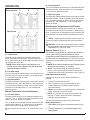
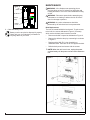
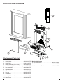
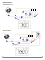
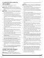
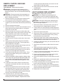
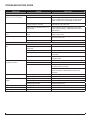
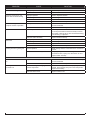
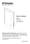
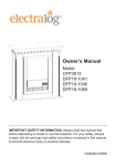
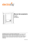
Service Manual
Mini Mozart
Model Number:
DFP15-1131 (No Remote)
DFP15-1132 (No Remote)
DFP15-1134 (Remote)
DFP15-1140 (Remote)
UL Part Number
690750XXXX
IMPORTANT SAFETY INFORMATION: Always read this manual first before attempting to service this
fireplace. For your safety, always comply with all warnings and safety instructions contained in this
manual to prevent personal injury or property damage.
Dimplex North America Limited
1367 Industrial Road Cambridge ON Canada N1R 7G8
1-888-346-7539 www.dimplex.com
In keeping with our policy of continuous product development, we reserve the right to make changes without notice.
© 2011 Dimplex North America Limited
REV
PCN
DATE
00
-
4-JAN-12
7400530000R00
TABLE OF CONTENTS
OPERATION. . . . . . . . . . . . . . . . . . . . . . . . . . . . . . . . . . . . . . . . . . . . . . . . . . . . . . . . . 3
MAINTENANCE . . . . . . . . . . . . . . . . . . . . . . . . . . . . . . . . . . . . . . . . . . . . . . . . . . . . . . 4
EXPLODED PARTS DIAGRAM . . . . . . . . . . . . . . . . . . . . . . . . . . . . . . . . . . . . . . . . . . 5
WIRING DIAGRAM. . . . . . . . . . . . . . . . . . . . . . . . . . . . . . . . . . . . . . . . . . . . . . . . . . . . 6
SWITCH REPLACEMENT – ON/OFF, LOW/HIGH HEAT . . . . . . . . . . . . . . . . . . . . . . 7
HEATER ASSEMBLY REPLACEMENT . . . . . . . . . . . . . . . . . . . . . . . . . . . . . . . . . . . . 7
FLICKER MOTOR/FLICKER ROD REPLACEMENT. . . . . . . . . . . . . . . . . . . . . . . . . . 8
POWER CORD REPLACEMENT. . . . . . . . . . . . . . . . . . . . . . . . . . . . . . . . . . . . . . . . . 8
REMOTE CONTROL RECEIVER REPLACEMENT. . . . . . . . . . . . . . . . . . . . . . . . . . . 9
LIGHT HARNESS REPLACEMENT. . . . . . . . . . . . . . . . . . . . . . . . . . . . . . . . . . . . . . . 9
TROUBLESHOOTING GUIDE . . . . . . . . . . . . . . . . . . . . . . . . . . . . . . . . . . . . . . . . . . 10
Always use a qualified technician or service agency to repair this fireplace.
! NOTE: Procedures and techniques that are considered important enough to emphasize.
CAUTION: Procedures and techniques which, if not carefully followed, will result in damage to the
equipment.
Warning: Procedures and techniques which, if not carefully followed, will expose the user to the
risk of fire, serious injury, or death.
2
www.dimplex.com
OPERATION
Figure 1
Without Remote
C
B
A
B - Low Heat Switch
The Low Heat Switch supplies power to the heater fan and
the heater element. When the switch is in the ON position
(“ I ”) the heater operates on LOW.
C - High Heat Switch
The High Heat Switch supplies power to the heater fan and
the heater element. When the switch is in the ON position
(“ II ”) the heater operates on HIGH. The Low Heat Switch
must also be in the ON position (“ I ”) for the high heat
setting to operate.
Resetting the Temperature Cutoff Switch
With Remote
C
B
A
Should the heater overheat, an automatic cut out will turn
the fireplace off and it will not come back on without being
reset. It can be reset by switching the On/Off Switch to Off
and waiting five (5) minutes before switching the unit back
on.
! NOTE: If operating the unit with a remote control, the
remote may require re-initializing after turning the power
off.
CAUTION: If you need to continuously reset the heater,
disconnect power and call Dimplex customer service at
1-888-DIMPLEX (1-888-346-7539).
Manual Controls for Units without Remote
A - On/Off Switch
The power switch controls the electricity supply to the
heater, flame effect and pilot light. When the switch is in
the “ I ” position the unit is ON and when the switch is in the
“ O “ position the unit is OFF.
! Note: When the pilot light is lit but flames are not
present, power is still supplied to unit and flame effect
light bulb should be replaced.
B - Low Heat Switch
The Low Heat Switch supplies power to the heater fan and
the heater element. When the switch is in the ON position
(“ I ”) the heater operates on LOW.
C - High Heat Switch
The High Heat Switch supplies power to the heater fan and
the heater element. When the switch is in the ON position
(“ II “) the heater operates on HIGH. The Low Heat Switch
must also be in the ON position (“ I “) for the high heat
setting to operate.
Manual Controls for Units with Remote
A - 3-Position Switch
The power switch has two (2) On positions marked with “ I
” and “ II ”. The “ I ” position is for manual operation. In this
position the remote control is bypassed.
The “ II ” position is for operating the unit with the provided
remote control. When in “ II ” position the unit is operated
with the ON and OFF buttons of the remote control.
When the switch is in the center (“ O ”) position the unit is
off.
Remote Control (Figure 2)
The fireplace is supplied with an integrated On/Off remote
control, that is factory synchronized with the firebox.
To operate, push the ON button to turn fireplace on, push
the OFF button to turn the fireplace off. The amount of heat
produced will be dependant on positioning of manual heat
controls.
! Note: Ensure that the fireplace’s On/Off switch is set to
the remote control setting (“ II ” position).
! NOTE: Before attempting any operation with the
remote control, pull the plastic insulator strip out from
between the remote casing and battery cover (Figure 2).
Initialization/Reprogramming
Follow these steps for remote control initialization, if
required:
1. Set the 3-Position Switch to OFF.
2. Wait a minimum of five (5) seconds and set the 3
Position Switch to the Remote position (refer to
Operation Section).
3. Within 10 seconds of re-acquiring power, press the ON
button located on the remote control.
! NOTE: You will have only 10 seconds to perform this
last step. Failure to do so will result in these steps
needing to be followed again.
This will synchronize the remote control and receiver.
Battery Replacement
1. Slide battery cover open on the remote control (Figure
3).
2. Correctly install one (1) 12 Volt (A23) battery in the
battery holder.
3
Figure 2
MAINTENANCE
arning: If the fireplace was operating prior to
W
servicing allow at least 10 minutes for light bulbs and
heating elements to cool off to avoid accidental burning
of skin.
Warning: Disconnect power before attempting any
maintenance or cleaning to reduce the risk of electric
shock or damage to persons.
On
Button
Off Button
Plastic
Strip
WARNING: Any other maintenance should be
performed by an authorized service representative.
Battery
Cover
Bulb Replacement
3. Close the battery cover.
Battery must be recycled or disposed of properly.
Check with your Local Authority or Retailer for
recycling advice in your area.
The bulb is located behind the back panel. To gain access
to the bulb, the screws indicated in Figure 3 (4 screws)
which secure the back panel must be removed.
• Remove and slide out panel as indicated on Figure 4.
• Remove the defective lamp by unscrewing it as shown
in Figure 4.
• Replace with a 60W E12 clear chandelier or
candelabra bulb. Take care not to over-tighten the bulb.
•
Refit the back panel and secure with the screws.
! Note: When the unit is not in use, unplug the power
cord and neatly coil the power cord and set it beside the
unit.
Figure 3
Figure 4
4
www.dimplex.com
EXPLODED PARTS DIAGRAM
13
3
14
11
10
2
7
1
9
Replacement Parts List
8
1. Flicker Motor . . . . . . . . . . . . . . . . . . . . . 2000220100RP
2. Flicker Rod . . . . . . . . . . . . . . . . . . . . . . . 5902110100RP
3. Heater Assembly (with Cutout). . . . . . . 2203530200RP
4. On/Off Switch (Models with no remote). 2800070700RP
5. Low Heat Switch . . . . . . . . . . . . . . . . . . 2800070900RP
6. High Heat Switch . . . . . . . . . . . . . . . . . 2800071000RP
7. Power Cord . . . . . . . . . . . . . . . . . . . . . . 4100010700RP
8. Log Set . . . . . . . . . . . . . . . . . . . . . . . . . 0440580100RP
9. Front Glass . . . . . . . . . . . . . . . . . . . . . . 5902080100RP
10. Partially Reflective Glass . . . . . . . . . . . 5902090100RP
11. Light Socket . . . . . . . . . . . . . . . . . . . . . 4200090200RP
4
6
12
5
Models with Remote
12. 3-Position Switch . . . . . . . . . . . . . . . . . 2800071100RP
13. Remote Control. . . . . . . . . . . . . . . . . . . 3000370500RP
14. Remote Control Receiver . . . . . . . . . . . 3000380200RP
5
WIRING DIAGRAM
Model Without Remote
WIRES FROM
FLICKER MOTOR
WIRING SCHEMATIC
SWITCH 1
MAIN ON/OFF
CAPACITOR
SWITCH 2
LOW HEAT
ON/OFF
L1
120V~
60Hz
FLICKER
MOTOR
LIGHT
BULB
PILOT
LIGHT
BLOWER
MOTOR
CUT-OUT
SWITCH 2
HIGH HEAT
ON/OFF
HEATING
ELEMENTS
Model With Remote
WIRES FROM
PILOT LIGHT
WIRES FROM
FLICKER MOTOR
SWITCH 1
MAN. MODE/
OFF/
REMOTE MODE
CAPACITOR
SWITCH 2
LOW HEAT
ON/OFF
L1
120V~
60Hz
FLICKER
MOTOR
LIGHT
BULB
PILOT
LIGHT
CUT-OUT
BLOWER
MOTOR
SWITCH 2
HIGH HEAT
ON/OFF
HEATING
ELEMENTS
6
www.dimplex.com
SWITCH REPLACEMENT – ON/OFF,
LOW/HIGH HEAT
Tools Required: Phillips head Screwdriver
Warning: If the fireplace was operating prior to
servicing allow at least 10 minutes for light bulbs and
heating elements to cool off to avoid accidental burning
of skin.
Warning: Disconnect power before attempting any
maintenance or cleaning to reduce the risk of electric
shock or damage to persons.
1. Remove the twelve (12) screws which mount the firebox to the back of the mantel/cabinet. (Figure 5)
2. Pull the firebox out from behind the mantel and place it
upright on your work surface with the back panel facing
you.
3. Remove the light access panel. (Figure 3)
4. Remove the three (3) screws along the bottom edge
which secure the bottom panel to the back panel.
5. Carefully lay the firebox onto your work surface with the
front glass facing up.
6. Remove the eight (8) remaining screws which secure
the bottom panel and front control panel to the upper
chassis of the firebox. (On each side there are two (2)
along the side of the front control panel and two (2)
along the bottom edge.)
7. Gently pull the bottom panel away from the firebox,
while supporting the front glass. Remove glass and
place the glass in a safe place.
8. Continue removing the bottom panel being careful not
to strain any of the connected wires.
9. Locate the defective switch mounted to the lower front
Figure 5
cover. Disconnect the wiring connections, noting their
original locations.
! NOTE: A flat head screwdriver can be used to gently
pry between the end of the connector and the switch to
release the wires.
10. Depress the retainer clips on the rear of the switch and
push the switch out of the heater assembly cover.
11. Properly orient the new switch and connect all of the
wiring connections.
12. Reassemble in the reverse order.
HEATER ASSEMBLY REPLACEMENT
Tools Required: Phillips head Screwdriver
Warning: If the fireplace was operating prior to
servicing allow at least 10 minutes for light bulbs and
heating elements to cool off to avoid accidental burning
of skin.
Warning: Disconnect power before attempting any
maintenance or cleaning to reduce the risk of electric
shock or damage to persons.
1. Remove the twelve (12) screws which mount the firebox to the back of the mantel/cabinet. (Figure 5)
2. Pull the firebox out from behind the mantel and place it
upright on your work surface with the back panel facing
you.
3. Remove the seven (7) screws along the upper edge of
the side and rear panels, which secure the top panel to
the sides: two (2) on the left panel; two (2) on the right
panel; three (3) on the rear panel.
4. Carefully lift the top panel off, being careful that the
heater assembly does not catch on anything, as there
are wires attached to the heater assembly.
5. Rotate the assembly so that the top of the top panel is
resting on the sides of the unit, and the heater assembly is facing up.
6. Release the heater assembly by removing the four (4)
screws which secure the two (2) mounting brackets to
the top panel (two screws on each bracket).
7. Remove the two (2) screws from each mounting bracket which secure the brackets to the heater assembly.
8. Transfer wiring connections from the original heater assembly to the replacement heater assembly.
! Note: Some of the wires will have a “piggy-back” connection allowing 2 wires to connect onto 1 prong. It is helpful to keep these “piggy-back” connections together when
transferring these wires.
9. Reassemble in the reverse order.
7
FLICKER MOTOR/FLICKER ROD
REPLACEMENT
Tools Required: Phillips head Screwdriver
Wire cutters
Warning: If the fireplace was operating prior to
servicing allow at least 10 minutes for light bulbs and
heating elements to cool off to avoid accidental burning
of skin.
Warning: Disconnect power before attempting any
maintenance or cleaning to reduce the risk of electric
shock or damage to persons.
1. Remove the twelve (12) screws which mount the firebox to the back of the mantel/cabinet. (Figure 5)
2. Pull the firebox out from behind the mantel and place it
upright on your work surface with the back panel facing
you.
3. Remove the light access panel.
4. Remove the seven (7) screws around the bottom of the
firebox that secure the bottom panel on: 3 along the
back and 2 on each side.
5. Remove the lower set of screws on either side of the
light access panel cutout, these secure the interior light
socket and flicker motor bracket to the back panel.
6. Carefully lay the firebox onto your work surface with the
front glass facing up.
7. Remove the set of screws on either side of the control
panel.
8. Gently pull the bottom panel away from the firebox,
while supporting the front glass. Remove glass and
place the glass in a safe place.
9. Continue removing the bottom panel, being careful not
to strain any of the connected wires.
10. Remove the reflector rod from the flicker motor by pulling the end of the rod to the left and separating it from
the rubber sleeve.
11. Remove the rubber sleeve from the motor shaft.
12. Lift the mounting bracket that the light socket and the
flicker motor are attached to out of the unit.
13. Remove the two (2) screws that secure the flicker motor to the bracket and replace with new motor.
14. Remove the original flicker motor by cutting the connecting wires at the flicker motor, to allow enough
remaining wire to strip and connect to the new flicker
motor.
15. Strip 1/2” off of the remaining wire, and using appropriate wire connectors attach the wires from the new
flicker motor to the wires within the firebox.
16. Reassemble in the reverse order.
POWER CORD REPLACEMENT
Tools Required: Phillips head Screwdriver
Needle nose pliers
Warning: If the fireplace was operating prior to
servicing allow at least 10 minutes for light bulbs and
heating elements to cool off to avoid accidental burning
of skin.
Warning: Disconnect power before attempting any
maintenance or cleaning to reduce the risk of electric
shock or damage to persons.
1. Remove the twelve (12) screws which mount the firebox to the back of the mantel/cabinet. (Figure 5)
2. Pull the firebox out from behind the mantel and place it
upright on your work surface with the back panel facing
you.
3. Remove the light access panel.
4. Remove the seven (7) screws around the bottom of the
firebox that secure the bottom panel on: 3 along the
back and two (2) on each side.
5. Remove the lower set of screws on either side of the
light access panel cutout, these secure the interior light
socket and flicker motor bracket to the back panel.
6. Carefully lay the firebox onto your work surface with the
front glass facing up.
7. Remove the set of screws on either side of the control
panel.
8. Gently pull the bottom panel away from the firebox,
while supporting the front glass. Remove glass and
place the glass in a safe place.
9. Continue removing the bottom panel, being careful not
to strain any of the connected wires.
10. Remove the remaining eight (8) screws which secure
the log-set and the log-set bracket; four (4) on the left
and four (4) on the right lower side panels.
11. Lift the logs and the bracket out of the firebox. There
are wires connected to the log set, so carefully set it
beside the firebox.
12. Remove the partially reflective glass by sliding it down
a few inches, then spread the sides apart slightly until
you are able to lift the partially reflective glass out of
the unit. Place the partially reflective glass in a safe
location.
13. Locate the terminal block to which the power cord wires
are connected. Release the power cord wires from
the terminal block by removing the screw from each
corresponding terminal, then pulling the wire out of the
terminal.
14. With needle nosed pliers, squeeze and push the power
cord grommet out of the side panel of the fireplace
chassis. Remove the original power cord and discard
it.
15. Insert the new power cord wires through the same
opening as the original. With needle nosed pliers,
squeeze and push the new grommet in place of the
original, securing the power cord to the chassis.
16. Connect the new power cord into the terminal block following the original configuration.
17. Reassemble in the reverse order.
8
www.dimplex.com
REMOTE CONTROL RECEIVER
REPLACEMENT
Tools Required: Phillips head Screwdriver
Warning: If the fireplace was operating prior to
servicing allow at least 10 minutes for light bulbs and
heating elements to cool off to avoid accidental burning
of skin.
Warning: Disconnect power before attempting any
maintenance or cleaning to reduce the risk of electric
shock or damage to persons.
1. Remove the twelve (12) screws which mount the firebox to the back of the mantel/cabinet. (Figure 5)
2. Pull the firebox out from behind the mantel and place it
upright on your work surface with the back panel facing
you.
3. Remove the light access panel.
4. Remove the seven (7) screws around the bottom of the
firebox that secure the bottom panel on: 3 along the
back and 2 on each side.
5. Remove the lower set of screws on either side of the
light access panel cutout, these secure the interior light
socket and flicker motor bracket to the back panel.
6. Carefully lay the firebox onto your work surface with the
front glass facing up.
7. Remove the set of screws on either side of the control
panel.
8. Gently pull the bottom panel away from the firebox,
while supporting the front glass. Remove glass and
place the glass in a safe place..
9. Continue removing the bottom panel, being careful not
to strain any of the connected wires.
10. Remove the remaining eight (8) screws which secure
the log-set and the log-set bracket; four (4) on the left
and four (4) on the right lower side panels.
11. Lift the logs and the bracket out of the firebox. There
are wires connected to the log set, so carefully set it
beside the firebox.
12. Remove the partially reflective glass by sliding it down
a few inches, then spread the sides apart slightly until
you are able to lift the partially reflective glass out of
the unit. Place the partially reflective glass in a safe
location.
13. Locate the remote control receiver mounted on the
back panel, and transfer the wires to the new remote
control receiver.
14. Remove the original remote control receiver from the
mounting tabs located on the 4 corners of the board.
This can be done by cutting the tips of the tabs with
wire cutters or squeezing the tab inward and lifting the
receiver off the remainder of the tabs.
15. If the tabs were cut, remove the remainder of the
original mounting tabs by pushing them out through
the back panel of the fireplace. Replace with the new
mounting tabs provided with the new receiver into the
same location on the back panel
16. Gently push the new remote control receiver onto the
mounting tabs.
17. Reassemble in the reverse order.
LIGHT HARNESS REPLACEMENT
Tools Required: Phillips head Screwdriver
Warning: If the fireplace was operating prior to
servicing allow at least 10 minutes for light bulbs and
heating elements to cool off to avoid accidental burning
of skin.
Warning: Disconnect power before attempting any
maintenance or cleaning to reduce the risk of electric
shock or damage to persons.
1. Remove the twelve (12) screws which mount the firebox to the back of the mantel/cabinet. (Figure 5)
2. Pull the firebox out from behind the mantel and place it
upright on your work surface with the back panel facing
you.
3. Remove the light access panel.
4. Remove the seven (7) screws around the bottom of the
firebox that secure the bottom panel: three (3) along
the back and two (2) on each side.
5. Remove the lower set of screws on either side of the
light access panel cutout, these secure the interior light
socket and flicker motor bracket to the back panel.
6. Carefully lay the firebox onto your work surface with the
front glass facing up.
7. Remove the set of screws on either side of the control
panel.
8. Gently pull the bottom panel away from the firebox,
while supporting the front glass. Remove glass and
place the glass in a safe place.
9. Continue removing the bottom panel, being careful not
to strain any of the connected wires.
10. Lift the mounting bracket that the light socket and the
flicker motor are attached to out of the unit.
11. Remove the light bulb from the socket and put in a safe
place.
12. Replace the original light socket by removing the retaining plate and installing the new socket.
13. Cut the connecting wires, from the original light socket,
that run into the top portion of the firebox.
14. Strip 1/2” off of the remaining wire, and using appropriate wire connectors, attach the wires from the new light
socket to the wires within the firebox.
15. Reassemble in the reverse order.
9
TROUBLESHOOTING GUIDE
Problem
Cause
Solution
General
Circuit breaker trips or fuse
blows when unit is turned on
Short in unit wiring.
Trace wiring in unit.
Improper circuit current rating
Additional appliances may exceed the current rating
of the circuit breaker or fuse. Plug unit into another
outlet or install unit on a dedicated 15 amp circuit.
Unit turns on or off by itself
Remote Control has a similar frequency
to other remotes in the area.
Replace Remote Control. Initialize Remote Control
and Remote Control Receiver
Radio frequency disturbance from outside sources.
Replace Remote Control and Remote Control Receiver, where necessary. Initialize Remote Control
and Receiver
Lights dim in room while the unit
is on
Unit is drawing close to circuit current
rating
Move the unit to another outlet or install unit on a dedicated 15 amp circuit
Power cord gets warm
Normal Operation
The power cord may get slightly warm to the touch
when the heater is on
Defective power cord
Replace power cord if cord gets hot to the touch.
Appearance
Fireplace does not turn on Manu- Improper operation
ally
No incoming voltage from the electrical
wall socket
Fireplace does not turn on using
the Remote Control
Refer to Operation Section
Check Fuse/Breaker Panel
Loose wiring
Check wiring connections
Defective On/Off or 3-Position Switch
Replace On/Off or 3-Position Switch (Depending on
the model)
Defective Remote Control Receiver
Replace Remote Control Receiver. Initialize with
Remote Control
Improper operation
Refer to Operation Section
Remote Control not initialized to fireplace Initialize the Remote Control
Remote Control not working.
Install new battery into the Remote Control. Reinitialize remote where necessary
Replace Remote Control or Remote Control Receiver,
where necessary. Initialize Remote Control and
Receiver.
Flame Frozen
Loose wiring
Check wiring connections
Defective Flicker motor
Replace Flicker motor
Burnt out light bulbs
Replace light bulbs
Loose wiring
Check wiring connections
Defective light harness
Replace light harness
Log set dim, not glowing
Burnt light bulbs
Replace light bulbs
Flame Shudder
Defective Flicker motor
Replace Flicker motor
Light leaking around the log set
Log set not positioned properly
Check log set for proper fit
Flame not bright or flame not
visible
10
www.dimplex.com
Problem
Cause
Solution
Heater
Heater is not turning off
Heater is not turning on, but
flame effect is still functioning
Heater is turning off after a
couple of minutes of operation
Heater emits an odor
Heater fan turns on but heater
lacks heat
Improper operation
Refer to Operation Section
Defective Thermostat
Replace Thermostat
Improper operation
Refer to Operation Section
Loose wiring
Trace wiring in unit.
Defective Thermostat
Replace Thermostat
Defective Heater Assembly
Replace Heater Assembly
Build up of dirt/dust in heater assembly
Ensure that exterior intake louvers and firebox cavity
are free of dirt/dust.
Defective Heater Assembly
Replace Heater Assembly
Normal Operation
Normal operation is when the heater emits an odor
for a brief period after the heater is initially turned on.
The heater is burning off any dust accumulated during
manufacturing or operation.
Defective Heater Assembly
Replace Heater Assembly
Improper operation
Refer to Operation Section
Loose wiring
Trace wiring in unit
Defective Thermostat
Replace Thermostat
Defective Heater Assembly
Replace Heater Assembly
Normal Operation
Small glowing sections of the element are considered
normal.
Defective Heater Assembly
If larger glowing sections are causing the heater to trip
the thermal cutout, unplug unit, discontinue use and
replace heater assembly.
Excessive noise with the heater
on
Dirty blower assembly
Ensure that exterior intake louvers and firebox cavity
are free of dirt/dust.
Defective Heater Assembly
Replace Heater Assembly
Grinding or excessive noise with
the heater off
Flicker rod hitting or rubbing against
internal components
Ensure rod is straight and mounted properly in the
bracket, spinning freely away from other components.
Replace if necessary.
Defective Flicker motor
Replace Flicker motor
Heating element is glowing red
Noise
11