1
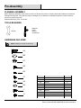
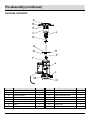
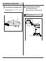
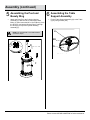
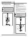
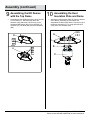
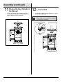
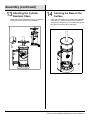
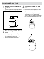
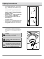
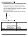
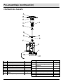
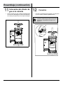
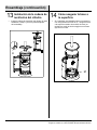
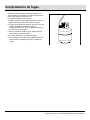
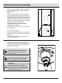
Item #660535
Model # PG139HDS
USE AND CARE GUIDE
PG139HDS PATIO HEATER
Questions, problems, missing parts? Before returning to the store,
call Hampton Bay Customer Service
8 a.m. - 6 p.m., EST, Monday-Friday
855-HD-HAMPTON
HAMPTONBAY.COM
THANK YOU
We appreciate the trust and confidence you have placed in Hampton Bay through the purchase of this patio heater. We strive to
continually create quality products designed to enhance your home. Visit us online to see our full line of products available for your
home improvement needs. Thank you for choosing Hampton Bay!
Table of Contents
Table of Contents .......................................................... 2
Safety Information ......................................................... 2
Warranty ......................................................................... 4
Pre-Assembly ................................................................ 5
Planning Assembly ..................................................... 5
Tools required ............................................................ 5
Hardware Included ..................................................... 5
Package Contents ...................................................... 6
Assmebly ....................................................................... 7
Installing LP Gas Tank ............................................... 14
Checking for Leaks ..................................................... 15
Lighting Instruction ................................................... 16
Care and Maintenance ............................................... 17
Troubleshooting.......................................................... 17
Safety Information
1. The installation must conform with local codes or, in
the absence of local codes, with the National Fuel
Gas Code, ANSI Z223.1 /NFPA 54, Natural Gas and
Propane Installation Code, CSA B149.1, or Propane
Storage and Handling Code, B149.2.
7. More frequent cleaning may be required as
necessary. It is imperative that the control
compartment, burners and circulating air
passageways of the heater to kept clean.
8. Use this appliance in outdoor areas described below:
2. Minimum clearance to the combustible materials is
3.61 ft. (1100 mm).
(a) With walls on all sides, but at least one
permanent opening at ground level and no overhead
cover.
3. Perform a leak test with a soapy solution:
(a) To check gas connections.
(b) Within a partial enclosure that includes overhead
cover and no more than two walls. These walls may
be parallel, or at right angles to each other.
(b) After connecting a new cylinder.
(c) Upon re-assembly after disassembly.
(c) Within a partial enclosure that includes overhead
cover and no more than two walls. The following
shall apply:
Please refer to the leak test procedure indicated in
this instruction manual on page 15.
Replace the hose assembly prior to the appliance
being put into operation if there is evidence of
excessive abrasion or wear, or if the hose is
damaged. The pressure regulator and hose
assembly supplied with the appliance must be used.
The replacement hose assembly / regulator shall be
that specified by the manufacturer.
(i) One wall that is equivalent to at least 25% of the
total wall area is completely open.
(ii) 30% or more in total of the remaining wall area is
open and unrestricted.
9. The LP-gas supply cylinder to be used must be:
(a) Constructed and marked in accordance with the
Specifications for LP-gas cylinders of the U.S.
Department of Transportation of Dangerous Goods
and Commission, CAN/CSA-B339, as applicable;
4. If you don’t feel the heater is on a stable surface,
use a ground screw to fix the base of the heater on
the surface where the heater is installed. Fix the
base on an incline no wider than 15 degrees.
(b) Provided with a listed overfilling prevention
device;
5. Place the propane hose with regulator assembly out
of pathways where people may trip over it or in
areas where the hose will not be subjected to
accidental damage.
(c) Provided with a cylinder connection device
compatible with the connection for the appliance.
10. Disconnect the cylinder when the appliance is not in
use.
6. This heater is equipped with a battery-operated
ignition device; please refer to the assembly
instructions on page 10.
11. Storage of an appliance indoors is permissible only if
the cylinder is disconnected and removed from the
appliance.
2
Safety Information (continued)
12. Store the cylinder outdoors in a well-ventilated area
(not in a building, garage, or other enclosed area)
out of the reach of children.
WARNING:
Improper installation, adjustment, alteration, service
or maintenance can cause property damage, injury
or death. Read the installation, operating and
maintenance instructions thoroughly before
installing or servicing this equipment.
13. The cylinder used must include a collar to protect
the cylinder valve.
14. Do not store a spare LP-gas cylinder under or near
this appliance.
WARNING:
For outdoor use only.
15. Never fill the cylinder beyond 80 percent full.
16. Place the dust cap tightly on the cylinder valve outlet
whenever the cylinder is not in use. Install only the
type of dust cap on the cylinder valve that is
provided with the cylinder valve. Other types of caps
or plugs may result in a propane leak.
WARNING:
Children and adults should be alerted to the hazards
of high surface temperatures and should stay away
to avoid burns or clothing ignition.
Young children should be carefully supervised when
they are in the area of the heater.
Any guard or other protective device removed for
servicing the heater must be replaced prior to
operating the heater.
Installation and repair should be done by qualified
service person, the heater should be inspected
before use and at least annual by a qualified service
person.
Keep the appliance area clear and free from
combustible materials, gasoline and other
flammable vapors and liquids.
Do not obstruct the flow of combustion and
ventilation air.
Keep the ventilation opening(s) of the cylinder
enclosure free and clear from debris. Use this
appliance in a well-ventilated space only. Do not
use it in a building, garage, or any other enclosed
area.
17. Inspect the visible portion of the hose before each
use of the appliance.
18. More frequent cleaning may be required as
necessary. It is imperative that the control
compartment, burners and circulating air
passageways of the heater be kept clean.
19. Every part of the heater shall be secure against
displacement and shall be constructed to maintain a
fixed relationship between essential parts under
normal and reasonable conditions of handling and
usage. Parts not permanently secured shall be
designed so they cannot be incorrectly assembled
and cannot be improperly located or misaligned in
removing or replacing during cleaning or other
servicing.
CAUTION:
Materials or items when stored under the heater will
be subjected to intense heat and could be seriously
damaged.
Clothing or other flammable materials should not be
hung on the heater, or placed on, under or near the
heater.
DANGER:
If you smell gas:
1. Shut off gas to the appliance.
2. Extinguish any open flame.
3. If odor continues, keep away from the appliance
and immediately call your gas supplier or fire
department.
WARNING:
Do not store or use gasoline or other flammable
vapors and liquids in the vicinity of this or any other
appliance.
An LP-cylinder not connected for use shall not be
stored in the vicinity of this or any other appliance.
3
HAMPTONBAY.COM
Please contact 855-HD-HAMPTON for further assistance.
Warranty
ONE-YEAR LIMITED WARRANTY
The appliance has been manufactured under the highest standards of quality and workmanship. We warrant to the
original consumer / purchaser that all aspects of this product will be free of defects in material and workmanship for one (1)
year from the date of purchase. A replacement for any defective part will be supplied free of charge for installation by the
consumer. Defects or damage caused by the use of other than genuine parts are not covered by this warranty. This
warranty shall be effective from the date of purchase as shown in the purchaser’s receipt. This warranty is valid for the
original consumer purchaser only and excludes industrial, commercial or business use of the product, product damage
due to shipment or failure which results from alteration, product abuse, or product misuse, where performed by a
container, service company, or consumer. We will not be responsible for labor charges and/or damage incurred in
installation, repair or replacement, nor for incidental or consequential damage. This warranty gives you specific legal
rights, and you may also have other rights that vary from state to state.
4
Pre-Assembly
PLANNING ASSEMBLY
Before beginning assembly of this product, make sure all parts are present. Compare parts with Hardware Included and
Package Contents lists. If any part is missing or damaged, do not attempt to assemble the product. Contact customer
service for replacement parts.
Estimated Assembly Time: 30 minutes
TOOLS REQUIRED
Magnetic
Head
Phillips
Screwdriver
Wrench
HARDWARE INCLUDED
NOTE: Hardware not shown to actual size.
AA
BB
CC
DD
EE
FF
GG
HH
II
JJ
Part
Description
AA
BB
CC
DD
EE
FF
GG
M8 x 15 mm Bolt
8.5 mm Washer
M8 Nut
M5 x 10 Pan Head Bolt
ST 4.2 x 10 mm Screw
M5 x 8 mm Bolt
M5 Nut
4
4
4
3
4
12
15
HH
II
JJ
5 mm Washer
M6 x 10 Hexagon Head Bolt
M5 x 10 Pan Head Collar Bolt
15
4
5
5
Quantity
HAMPTONBAY.COM
Please contact 855-HD-HAMPTON for further assistance.
Pre-Assembly (continued)
PACKAGE CONTENTS
A
B
E
C
N
L
G
D
H
P
F
J
I
K
M
Part
Description
O
Quantity
Part
I
J
K
L
M
Wheel Assembly
Regulator & Hose Assembly
Cylinder Restraint Chain
Control Knob
Base
1
1
1
1
1
N
O
P
Upper Post Assembly
Weight Plate
Beauty Ring
1
1
1
A
B
Top Dome
KD Dome
1
4
C
D
E
F
G
H
Burner Assembly
Post
Heat Insulation Plate
Cylinder Housing Assembly
Table
Table Support Assembly
1
1
1
1
1
1
6
Description
Quantity
Assembly
1
□
2
Disassembling the Weight
Plate
Disassemble the Weight Plate (O) from the Base
(M) by loosening the 3/8 x 16 Nut (1).
□
Assembling the Wheel
Assembly
Attach the Wheel Assembly (l) to the Base (M) with
four Bolts (AA), Washers (BB), and Nuts (CC).
NOTE: The Weight Plate (O) will be used again
in step 3.
AA
I
M
CC
BB
M
3/8*16
Nut
1
O
AA
M8X15mm Bolt
X4
BB
8.5 mm Washer
X4
CC M8 Nut
7
X4
HAMPTONBAY.COM
Please contact 855-HD-HAMPTON for further assistance.
Assembly (continued)
□
4
Reinstall the Weight Plate (O) on the Base (M) with
the 3/8 x 16 Nut (1).
□
Assembling the Cylinder
Housing Assembly
Attach the Cylinder Housing Assembly (F) to the
Base (M) with five M5 x 10 Pan Head Collar Bolts
(JJ).
NOTE: The door is in the opposite position to
the wheel assembly (I).
3/
1ut
N
6
8*1
O
3
Assembling the Weight Plate
JJ
F
M
M
JJ M5 X 10Pan Head
Collar Bolt
8
X5
Assembly (continued)
5
□
6
Assembling the Post and
Beauty Ring
Attach the Post (D) to the Cylinder Housing
Assembly (F) with four M6 x 10 Hexagon Head
Bolts (II), then loosen the M5 x 10 mm Bolt (1) from
the Post (D), and put the Beauty Ring (P) through
the Post (D) on top of the Cylinder Housing
Assembly (F).
□
Assembling the Table
Support Assembly
Fix the Table Support Assembly (H) to the Table
(G) by using Screws (EE).
H
NOTE: The loosened M5 x 10 mm Bolt will be
used in the step 8.
EE
II
D
M5
1 X 10
P
G
mm Bolt
EE
ST4.2X10mm Screw
X 4
F
II
M6 X 10 Hexagon Head Bolt
X4
9
HAMPTONBAY.COM
Please contact 855-HD-HAMPTON for further assistance.
Assembly (continued)
7
□
8
Assembling the Table
Attach the Table Assembly (G and H) to the Post
(D).
□
□
NOTE: When the Table (G) is well attached,
please follow the steps below to adjust the
height:
a. Adjust the grip until it is vertical to the Post.
b. Adjust the height of the table as you like.
c. Fix the position of the table by turning the grip
clockwise.
d. Turn until the grip is fixed.
□
□
Assembling the Burner
Assembly
Feed the valve and gas hose and connect the
Burner Assembly (C) to the Post (D).
Feed the valve and gas hose into and go through
the Post (D).
Screw the Burner Assembly (C) onto the Post (D)
until the holes on the Upper Post Assembly (N) are
aligned to holes on top of the Post (D). Attach using
three M5 x 10 mm Pan Head Bolts (DD). Ensure
they are fully tightened.
Reassemble the M5 x 10 mm Bolt (1) to the Post
(D) in order to limit the height of the Table (G).
NOTE:
a. Open the igniter cap by unscrewing the cap
counterclockwise.
b. Take out the battery included in the pack of
Instruction manual.
c. Insert the battery to the igniter.
d. Screw the igniter cap back
D
G
H
C
- +
N
Battery
Ignltor
Ignitor
DD
D
DD
10
1
M5 X 10 mm Bolt
M5 X 10 Pan Head Bolt
X3
Assembly (continued)
9
□
10
Assembling the KD Domes
with the Top Dome
Assemble the four KD Domes (B) by using four M5
x 8 mm Bolts (FF), M5 Nuts (GG) and 5 mm
Washers (HH). Attach the Top Dome (A) to the
assembled KD Domes (B) by using eight M5 x 8
mm Bolts (FF), M5 Nuts (GG) and 5 mm Washers
(HH).
□
Attach the Heat Insulation Plate (E) onto the bracket
of the Burner Assembly (C); then attach the
Assembled KD Domes (B) with the Top Dome (A) to
the Burner Assembly (C), by using three M5 Nuts
(GG) and 5 mm Washers (HH).
GG
HH
A
B
GG
HH
FF
A
Assembling the Heat
Insulation Plate and Dome
B
E
GG
HH
FF
FF
M5 X 8 mm Bolt
X 12
GG
M5 Nut
X 12
HH
5 mm Washer
X 12
C
11
GG
M5 Nut
X3
HH
5 mm Washer
X3
HAMPTONBAY.COM
Please contact 855-HD-HAMPTON for further assistance.
Assembly (continued)
11
□
12
Placing the Gas Cylinder in
the Shroud
Put the gas cylinder (sold separately) into the
shroud. Keep the cylinder vertically upright on the
base to allow the vapors to escape.
□
Connection
Connect the Regulator & Hose Assembly (J) to the
cylinder (sold separately).
NOTE: Check for leaks after connecting the gas
cylinder every time according to the “Checking
for Leaks” section on page 15.
J
12
Assembly (continued)
13
□
14
Attaching the Cylinder
Restraint Chain
Attach the Cylinder Restraint Chain (K) to stabilize
the tank and close the door after assembly.
□
Securing the Base to the
Surface
If the heater is installed on a surface with a gradient
more than 15°, secure the base to the surface by
using two ground screws (not included) through the
two holes on the Base (M) as indicated.
KK
M
13
HAMPTONBAY.COM
Please contact 855-HD-HAMPTON for further assistance.
Installing LP Gas Tank
1
□
2
Specific size and capacity for
gas tank
To operate you will need a precision-filled standard
cylinder with specific size and capacity as shown.
□
lb
2020 lb
99 KGS
KGS
17.9 in / 45.5 cm
□
17.9 in /
45.5 cm
12.2 in / 31 cm
12.2
in / 31 cm
3
□
□
□
Disconnecting
a 20 lb. LP Gas
气瓶尺寸
Tank
Before disconnecting make sure the LP gas tank
valve is “OFF”.
Disconnect the gas line to the tank by turning the
knob counterclockwise until it is loose.
Store the LP gas tank in a proper location.
14
Connecting a 20 lb. LP Gas
Tank
Before connecting, be sure that there is no debris
caught in the head of the LP gas tank head of the
regulator valve or in the head of the burner and
burner ports.
Line up threads on the fitting with those on the
regulator and rotate clockwise until tight. HAND
TIGHTEN ONLY. DO NOT USE ANY HAND
TOOLS TO MAKE THIS CONNECTION. Be careful
not to cross threads when screwing in the FITTING.
Checking for Leaks
Your patio heater has been checked at all factory
connections for leakage. To check the connection at the
gas hose/regulator/cylinder:
a. Make a leakage solution by mixing 1 part liquid dish
soap and 3 parts water.
b. Spoon or brush several drops (or use a squirt bottle)
of the solution onto the gas hose/regulator and
regulator/cylinder and hose connection.
c. Turn on the gas cylinder valve. Inspect the
connections and look for bubbles.
d. If no bubbles appear, the connection is safe.
e. If bubbles appear, there is leakage. Loosen and retighten this connection. If it still leaks, please call
customer service.
15
Fig.14
HAMPTONBAY.COM
Please contact 855-HD-HAMPTON for further assistance.
Lighting Instructions
□
□
□
□
□
□
□
Turn the LP gas tank valve OFF. Push the control
knob in, turn OFF, and wait 5 minutes for any gas
to clear.
Turn the tank valve ON. Push the control knob in
and rotate to PUSH. Then push the igniter button
and control knob until the burner is ignited. If the
burner fails to remain lit or becomes extinguished,
repeat this step after 5 minutes of complete shutoff
period before relighting.
Once the burner has lit, continue to hold the control
knob in for 30 seconds, and then release.
Turn the control knob from LOW to HIGH to the
desired heat setting.
Igniter
push
LOW
For complete shutdown:
Turn the knob to the “Push” position first, then push
and turn to the “Off” position for complete shut off.
Turn the LP gas tank valve OFF before removing
the LP gas tank.
HIGH
If you are unable to ignite the heater using the
above instructions, insert a match through the hole
on the bottom of the burner diffuser to reach the
burner.
PUSH
PILOT
OFF
Fig.16
WARNING:
If at any time you are unable to light the burner and
smell gas, wait 5 minutes to allow gas to dissipate
before attempting to light the heater.
WARNING:
DO NOT touch or move the heater for at least 45
minutes after use. Allow emitter and dome to cool
before touching.
CAUTION:
Avoid inhaling fumes emitted from the heater’s first
use. Smoke and odor from the burning of oils used
in manufacturing will appear. Both smoke and odor
will dissipate after approximately 30 minutes. The
heater should NOT produce thick black smoke.
16
Care and Maintenance
□
To obtain the best performance from your heater make sure you perform the following maintenance activities on a
regular basis:
a. Keep exterior surfaces clean. Use warm soapy water for cleaning. Never use flammable or corrosive cleaning
agents. Keep the area around the burner and control assembly dry at all times.
b. Keep airflow unobstructed. Clear insect nests or webs away from your heater’s exterior and interior.
c. Carbon deposits may create a fire hazard. Clean the dome and emitter with warm soapy water if required.
d. Check your heater for signs of damage or wear and replace components as necessary.
e. Periodically check the hose located within the confines of the cylinder housing for damage.
f. Keep the ventilation clear and free from combustible materials, gasoline and other flammable vapors and liquids.
g. Keep the ventilation openings of the cylinder enclosure free and clear from debris.
h. Visually check the burner flame against the illustration below.
1. Flame should be blue with slight yellow tips.
2. Light the burner and rotate the knob from HIGH to LOW. You should see a smaller flame in the LOW position
than seen on HIGH. Always check the flame prior to each use. Perform a flame check prior to each use. If only
low flame is seen, refer to the “Troubleshooting” section.
High
Low
Troubleshooting
Problem
Possible Cause
Corrective Action
The burner does
not light.
1. The gas pressure is low.
2. The orifice is blocked.
3. The control knob is not in the “ON” position.
The burner flame is
low.
1.
2.
3.
4.
1. Turn the tank valve “OFF” and replace the
tank.
2. Clear the blockage.
3. Turn the control knob to “ON”.
1. Turn the tank valve “OFF” and replace the
tank.
2. Position the control knob at “High”.
3. Clear blockage.
4. Use a full tank.
5. Straighten the hose.
Wipe off before lighting.
There is carbon
build-up.
There is thick black
smoke.
The gas pressure is low.
The control knob is not positioned at “High”.
The burner jet may be partially blocked.
Outdoor temperature is less than 40°F and
the tank is less than 1/4 full.
5. The supply hose is bent or kinked.
A build-up of carbon can accumulate over time.
There is a blockage in the burner.
Remove blockage and clean the burner inside
and outside.
17
HAMPTONBAY.COM
Please contact 855-HD-HAMPTON for further assistance.
Questions, problems, missing parts? Before returning to the store,
call Hampton Bay Customer Service
8 a.m. - 6 p.m., EST, Monday-Friday
855-HD-HAMPTON
HAMPTONBAY.COM
Retain this manual for future use.
Núm. de artículo 660535
Núm. de modelo PG139HDS
GUÍA DE USO Y CUIDADO
CALEFACTOR DE PATIO PG139HDS
¿Tiene preguntas, problemas, o faltan piezas? Antes de regresar a la tienda,
llame a Servicio al Cliente de Hampton Bay
de lunes a viernes de 8 a.m. y 6 p.m., hora local del Este
855-HD-HAMPTON
HAMPTONBAY.COM
GRACIAS
Agradecemos la confianza que ha puesto en Hampton Bay a través de la compra de calefactor de patio. Nos esforzamos por
crear continuamente productos de calidad diseñados para mejorar su hogar. Visítenos en internet para ver nuestra línea completa
de productos disponibles para sus necesidades de mejorar su hogar. ¡Gracias por elegir a Hampton Bay!
Tabla de contenido
Tabla de contenido ....................................................... 2
Información de seguridad ............................................ 2
Garantía .......................................................................... 4
Pre-ensamblado ............................................................ 5
Planificación del ensamblaje ...................................... 5
Herramientas requeridas ............................................ 5
Herraje incluido .......................................................... 5
Contenido del paquete ............................................... 6
Ensamblaje .................................................................... 7
Instalación del tanque de gas PL .............................. 14
Comprobación de fugas ............................................. 15
Instrucciones de encendido ...................................... 16
Cuidado y mantenimiento .......................................... 17
Resolución de fallas ................................................... 17
Información de seguridad
1. La instalación debe hacerse conforme a los códigos
locales o, en ausencia de códigos locales, conforme
al Código Nacional de Gas Combustible, ANSI
Z223.1 /NFPA 54, Código de Instalación de Gas
Natural y Propano, CSA B149.1, o Código de
Almacenamiento y Manejo de Propano, B149.2.
6. Este calefactor está equipado con un dispositivo de
ignición operado por batería; consulte las
instrucciones de ensamblaje en la página 10.
7. Se puede requerir limpieza más frecuente según
sea necesario. Es imperativo que el compartimiento
de control, los quemadores y los pasillos de aire
circulante del calefactor se mantengan limpios.
2. El espacio libre mínimo para los materiales
combustibles es de 3.61 pies (1100 mm).
8. Use este aparato en áreas de exteriores como se
describe
a continuación:
(a) Con paredes en todos los lados, pero al menos
una abertura permanente a nivel del suelo y sin
cubierta superior.
(b) Dentro de un recinto parcial que incluya cubierta
superior y no más de dos paredes. Estas paredes
deben estar paralelas, o a ángulos rectos entre sí.
(c) Dentro de un recinto parcial que incluya cubierta
superior y no más de dos paredes. Aplicará lo
siguiente:
(i) Una pared equivalente a al menos el 25% del
área de pared total está completamente abierta.
(ii) 30% o más en total del área de pared restante
está abierta y sin restricciones.
3. Realice una prueba de fugas con una solución
jabonosa:
(a) Para revisar las conexiones de gas.
(b) Después de la conexión de un cilindro nuevo.
(c) En el reensamblaje después del desmontaje.
Consulte el procedimiento de prueba de fugas
indicado en este manual de instrucción en la página
15.
Reemplace el ensamblaje de la manguera antes de
que el aparato sea puesto en funcionamiento si hay
evidencia de abrasión excesiva o desgaste, o si la
manguera está dañada. Deben ser usados el
regulador de presión y el ensamblaje de la
manguera suministrados con el aparato. El
ensamblaje de la manguera de reemplazo/regulador
serán los especificados por el fabricante.
9. El cilindro de suministro de gas PL que se usará
debe:
(a) Estar construido y marcado de acuerdo con las
especificaciones para cilindros de gas PL del
Departamento de Transporte de Mercancías
Peligrosas y Puesta en Servicio de los EE.UU.,
CAN/CSA-B339, según corresponda;
(b) Tener provisto un dispositivo de prevención de
desborde listado;
(c) Tener provisto un dispositivo de conexión de
cilindro compatible con la conexión para el aparato.
4. Si cree que el calefactor no está en una superficie
estable, use un tornillo de tierra para fijar la base del
calefactor en la superficie donde está instalado el
calefactor. Fije la base en una pendiente no mayor
de 15 grados.
5. Coloque la manguera de propano con el ensamblaje
del regulador fuera de caminos donde las personas
puedan tropezar o en áreas donde la manguera no
estará sujeta a daños accidentales.
2
Información de seguridad (continuación)
10. Desconecte el cilindro cuando el aparato no esté en
uso.
11. El almacenamiento de un aparato en interiores es
permisible solamente si el cilindro está
desconectado y retirado del aparato.
12. Guarde el cilindro en exteriores en un área bien
ventilada (no en edificios, garajes, u otra área
encerrada) lejos del alcance de los niños.
13. El cilindro usado debe incluir un collarín para
proteger la válvula del cilindro.
ADVERTENCIA:
No almacene ni use gasolina ni otros vapores y
líquidos inflamables en la vecindad de este u otro
aparato.
Un cilindro de PL no conectado para uso no debe
almacenarse en la vecindad de este u otro aparato.
ADVERTENCIA:
La instalacion, ajuste, alteración, servicio o
mantenimiento inadecuados pueden causar daños
a la propiedad, lesiones o la muerte. Lea
completamente las instrucciones de instalación,
operación y mantenimiento antes de instalar o darle
servicio a este equipo.
14. No guarde un cilindro de gas PL de repuesto bajo o
cerca de este aparato.
15. Nunca llene el cilindro más allá del 80 por ciento de
su capacidad.
16. Coloque la tapa guardapolvo apretada en la salida
de la válvula del cilindro siempre que el cilindro no
esté en uso. Instale solo un tipo de tapa
guardapolvo en la válvula del cilindro que esté
provista con la válvula del cilindro. Otros tipos de
tapas o tapones pueden resultar en una fuga
de propano.
17. Inspeccione la porción visible de la manguera antes
de cada uso del aparato.
18. Se puede requerir limpieza más frecuente según
sea necesario. Es imperativo que el compartimiento
de control, los quemadores y los pasillos de aire
circulante del calefactor se mantengan limpios.
19. Cada pieza del calefactor debe estar segura contra
el desplazamiento y debe estar construida para
mantener una relación fija entre las piezas
esenciales bajo condiciones normales y razonables
de manejo y uso. Las piezas que no se encuentren
permanentemente seguras serán diseñadas para
que no puedan se ensambladas incorrectamente y
no puedan ser ubicadas incorrectamente o
desalineadas al retirarlas o reemplazarlas durante la
limpieza u otro mantenimiento.
PELIGRO:
Si huele gas:
1. Apague el gas al aparato.
2. Extinga cualquier llama abierta.
3. Si el olor continúa, aléjese del aparato y llame de
inmediato a su proveedor de gas o a los bomberos.
ADVERTENCIA:
Únicamente para uso en exteriores.
ADVERTENCIA:
Los niños y adultos deben ser alertados de los
peligros de las altas temperaturas superficiales y
deben permanecer lejos para evitar quemaduras o
ignición de la ropa.
Los niños pequeños deben ser supervisados
cuidadosamente cuando se encuentren en el área
del calefactor.
Cualquier protección u otros dispositivos de
protección retirados para darle servicio al calefactor
deben volver a colocarse antes de operar el
calefactor.
La instalación y reparación deben ser hechas por
personas de servicio calificadas, el calefactor debe
ser inspeccionado antes de su uso y al menos una
vez al año por una persona de servicio calificada.
Mantenga el área del aparato despejada y libre de
materiales combustibles, gasolina y otros vapores y
líquidos inflamables.
No obstruya el flujo de la combustión y el aire de
ventilación.
Mantenga las aberturas de ventilación del recinto del
cilindro libres y limpias de desechos. Use este
aparato en un espacio bien ventilado únicamente. No
lo use en edificios, garajes, u otra área encerrada.
PRECAUCIÓN:
Los materiales y artículos almacenados debajo del
calefactor estarán sujetos a intenso calor y podrían
resultar seriamente dañados. No debe colgarse
ropa y otros materiales inflamables en el calefactor,
ni colocarse sobre, debajo o cerca del calefactor.
3
HAMPTONBAY.COM
Póngase en contacto con el 855-HD-HAMPTON para asistencia adicional.
Garantía
GARANTÍA LIMITADA DE UN AÑO
El aparato ha sido fabricado bajo los más altos estándares de calidad y mano de obra. Garantizamos al
comprador/consumidor original que todos los aspectos de este producto estarán libres de defectos en materiales y mano
de obra durante un (1) año a partir de la fecha de compra. Se proporcionarán repuestos de cualquier pieza defectuosa
libre de cargos de instalación por el comprador. Los defectos o daños causados por el uso de piezas que no sean
genuinas no están cubiertos por esta garantía. Esta garantía será efectiva a partir de la fecha de compra como se
muestra en el recibo del comprador. Esta garantía es válida para el comprador consumidor original únicamente y excluye
el uso industrial, comercial o de negocios del producto, daños del producto debido a envío o falla que resulte de
alteración, abuso o mal uso del producto, realizado por un contenedor, empresa de servicio o consumidor. No seremos
responsables de cargos de mano de obra y/o daños incurridos en la instalación, reparación o reemplazo, ni tampoco por
daños incidentales o consecuentes. Esta garantía le otorga derechos legales específicos, y también puede tener otros
derechos que varían de un estado a otro.
4
Pre-ensamblado
PLANIFICACIÓN DEL ENSAMBLAJE
Antes de comenzar a ensamblar este producto, asegúrese de que todas las partes estén presentes. Compare las piezas
con el herraje incluido y las listas de contenido del paquete. Si hace falta alguna pieza o se encuentra dañada, no intente
ensamblar el producto. Póngase en contacto con servicio al cliente para las piezas de reemplazo.
Tiempo estimado de ensamblado: 30 minutos
HERRAMIENTAS REQUERIDAS
Destornillad
or Phillips
de cabeza
magnética
Llave
HERRAJE INCLUIDO
NOTA: No se muestra el herraje en el tamaño
real.
AA
BB
CC
DD
EE
FF
GG
HH
II
Pieza
Descripción
Cantidad
AA
BB
CC
DD
Perno M8 x 15 mm
Arandela de 8.5 mm
Tuerca M8
Perno de cabeza plana M5 x 10
4
4
4
3
EE
FF
GG
HH
II
Tornillo ST 4.2 x 10 mm
Perno M5 x 8 mm
Tuerca M5
Arandela de 5 mm
Perno de cabeza hexagonal M6 x 10
4
12
15
15
4
JJ
Perno de collar de cabeza plana M5 x 10
5
JJ
5
HAMPTONBAY.COM
Póngase en contacto con el 855-HD-HAMPTON para asistencia adicional.
Pre-ensamblaje (continuación)
CONTENIDO DEL PAQUETE
A
B
E
C
N
L
G
D
H
P
F
J
I
K
M
Pieza
Descripción
O
Cantidad
Pieza
I
Ensamblaje de la rueda
1
J
Ensamblaje del regulador y la
manguera
1
K
L
M
N
O
P
Cadena de restricción del cilindro
Perilla de control
Base
Ensamblaje del poste superior
Placa de peso
Aro decorativo
1
1
1
1
1
1
A
B
C
D
E
Domo superior
Domo KD
Ensamblaje del quemador
Poste
Placa de aislamiento de calor
1
4
1
1
1
F
G
H
Ensamble de la carcasa del cilindro
Mesa
Ensamblaje del soporte de la mesa
1
1
1
6
Descripción
Cantidad
Ensamblaje
1
□
Desmontaje de la placa de
peso
Desmonte la placa de peso (O) de la base (M)
aflojando la tuerca 3/8 x 16 (1).
2 Ensamblaje de la rueda
□
Instale el ensamblaje de la rueda (l) en la base (M)
con cuatro pernos (AA), arandelas (BB), y tuercas
(CC).
NOTA: La placa de peso (O) será usada de
nuevo en el paso 3.
AA
M
I
CC
BB
M
3/8*16
Nut
1
O
AA
M8X15mm Bolt
X4
BB
8.5 mm Washer
X4
CC M8 Nut
X4
7
HAMPTONBAY.COM
Póngase en contacto con el 855-HD-HAMPTON para asistencia adicional.
Ensamblaje (continuación)
□
4
Vuelva a instalar la placa de peso (O) en la base
(M) con la tuerca 3/8 x 16 (1).
□
Ensamblaje de la carcasa
del cilindro
Instale el ensamblaje de la carcasa del cilindro (F)
en la base (M) con cinco pernos de collar de
cabeza plana
M5 x 10 (JJ).
NOTA: La puerta está en la posición opuesta al
ensamblaje de la rueda (I).
3/
1ut
N
6
8*1
O
3
Ensamblaje de la placa de
peso
JJ
F
M
M
JJ M5 X 10Pan Head
Collar Bolt
8
X5
Ensamblaje (continuación)
5
□
Ensamblaje del poste y el aro
decorativo
Instale el poste (D) en el ensamblaje de la carcasa
del cilindro (F) con cuatro pernos de cabeza
hezagonal M6 x 10 (II), luego afloje el perno M5 x
10 mm (1) del poste (D), y ponga el aro decorativo
(P) a través del poste (D) en la parte superior del
ensamblaje de la carcasa del cilindro (F).
NOTA: El perno aflojado M5 x 10 mm será
usado en el paso 8.
6
□
Ensamblaje del soporte de la
mesa
Fije el soporte del ensamblaje del soporte de la
mesa (H) en la mesa (G) usando tornillos (EE).
H
EE
II
D
M5
1 X 10
P
G
mm Bolt
EE
ST4.2X10mm Screw
X 4
F
II
M6 X 10 Hexagon Head Bolt
X4
9
HAMPTONBAY.COM
Póngase en contacto con el 855-HD-HAMPTON para asistencia adicional.
Ensamblaje (continuación)
7 Ensamblaje de la mesa
□
8 Ensamblaje del quemador
Instale el ensamblaje de la mesa (G y H) en el
poste (D).
□
□
NOTA: Cuando la mesa (G) esté bien instalada,
siga los pasos a continuación para ajustar la
altura:
a. Ajuste la agarradera hasta que esté vertical
al poste.
b. Ajuste la altura de la mesa como le guste.
c. Fije la posición de la mesa girando la
agarradera hacia la derecha.
d. Gire hasta que la agarradera esté fija.
□
□
Ponga la válvula y la manguera de gas y conecte el
ensamblaje del quemador (C) al poste (D).
Ponga la válvula y la manguera de gas dentro y a
través
del poste (D).
Atornille el ensamblaje del quemador (C) sobre el
poste (D) hasta que los agujeros en el ensamblaje
del poste superior (N) estén alineados con los
agujeros en la parte superior del poste (D). Instale
usando tres pernos de cabeza plana M5 x 10 mm
(DD). Asegúrese de que estén completamente
apretados.
Reensamble el perno M5 x 10 mm (1) en el poste (D)
para limitar la altura de la mesa (G).
NOTA:
a. Abra la tapa del encendedor desatornillando
la tapa hacia la izquierda.
b. Saque la batería incluida en el paquete del
manual de instrucción.
c. Inserte la batería en el encendedor.
d. Atornille de nuevo la tapa del encendedor.
D
G
H
C
- +
N
Battery
Bateria
DD
D
DD
10
Ignltor
Encendedo
r
1
M5 X 10 mm Bolt
M5 X 10 Pan Head Bolt
X3
Ensamblaje (continuación)
9
□
10
Ensamblaje de los domos KD
con el domo superior
Ensamble los cuatro domos KD (B) usando cuatro
pernos M5 x 8 mm (FF), tuercas M5 (GG) y
arandelas de 5 mm (HH). Instale el domo superior
(A) en los domos KD ensamblados (B) usando ocho
pernos M5 x 8 mm (FF), tuercas M5 (GG) y
arandelas de 5 mm (HH).
□
Instale la placa de aislamiento de calor (E) sobre el
soporte del ensamblaje del quemador (C); luego
instale los domos KD ensamblados (B) con el domo
superior (A) en el ensamblaje del quemador (C),
usando tres tuercas M5 (GG) y arandelas de 5 mm
(HH).
B
GG
HH
A
GG
HH
FF
A
Ensamblaje de la placa de
aislamiento de calor y el
domo
B
E
GG
HH
FF
C
FF
M5 X 8 mm Bolt
X 12
GG
M5 Nut
X 12
HH
5 mm Washer
X 12
GG
M5 Nut
X3
HH
5 mm Washer
X3
11
HAMPTONBAY.COM
Póngase en contacto con el 855-HD-HAMPTON para asistencia adicional.
Ensamblaje (continuación)
11
□
12
Colocación del cilindro de
gas en la cubierta
Ponga el cilindro de gas (vendido separadamente)
en la cubierta. Mantenga el cilindro verticalmente
en la base para permitir que los vapores escapen.
□
Conexión
Conecte el ensamblaje del regulador y la manguera
(J) en el cilindro (vendido separadamente).
NOTA: Revise en busca de fugas después de
conectar el cilindro de gas cada vez de acuerdo
a la sección “Comprobación de fugas” en la
página 15.
J
12
Ensamblaje (continuación)
13
□
Instalación de la cadena de
restricción del cilindro
Instale la cadena de restricción del cilindro (K) para
estabilizar el tanque y cierre la puerta después
del ensamblaje.
14
□
Cómo asegurar la base a
la superficie
Si el calefactor está instalado sobre una superficie
con una pendiente de más de 15°, asegure la base
a la superficie usando dos tornillos de tierra (no
incluidos) a través de los dos agujeros en la base
(M) como se indica.
KK
M
13
HAMPTONBAY.COM
Póngase en contacto con el 855-HD-HAMPTON para asistencia adicional.
Instalación del tanque de gas PL
1
□
Tamaño y capacidad
específicos para el tanque de
gas
2
Para operar necesitará un cilindro estándar llenado
con precisión con tamaño y capacidad específicos
como
se muestra.
□
lb
2020 lb
99 KGS
KGS
17.9 in / 45.5 cm
□
17.9 pulg.
17.9 plg.
(45.5 cm)
12.2 in / 31 cm
12.2
pulg. (31 cm)
3
□
□
□
气瓶尺寸
Desconexión
de un tanque de
gas PL de 20 lb.
Antes de desconectar, asegúrese de que la válvula
del tanque de gas PL esté en la posición “OFF”.
Desconecte la línea de gas al tanque girando la
perilla hacia la izquierda hasta que esté floja.
Guarde el tanque de gas PL en un lugar adecuado.
14
Conexión de un tanque de
gas PL de 20 lb.
Antes de conectar, asegúrese de que no hayan
desechos en la cabeza del tanque de gas PL, la
cabeza de la válvula reguladora o en la cabeza del
quemador y puertos
del quemador.
Alinee las roscas en el accesorio con las del
regulador y gire hacia la derecha hasta que apriete.
APRIETE A MANO SOLAMENTE. NO USE
NINGUNA HERRAMIENTA MANUAL PARA
HACER ESTA CONEXIÓN. Tenga cuidado de no
cruzar las roscas cuando atornille en el
ACCESORIO.
Comprobación de fugas
Todas las conexiones de su calefactor de patio han
sido revisadas por completo en la fábrica en busca de
fugas. Para revisar la conexión en la
manguera/regulador/cilindro de gas:
a. Haga una solución para fugas mezclando 1 parte de
jabón líquido para platos con 3 partes de agua.
b. Ponga varias gotas con cuchara o brocha (o use una
botella rociadora) de la solución sobre la
manguera/regulador de gas y el regulador/cilindro y
la conexión de la manguera.
c. Abra la válvula del cilindro de gas. Inspeccione las
conexiones y busque burbujas.
d. Si no hay burbujas, la conexión es segura.
e. Si hay burbujas, hay fuga. Afloje y apriete de nuevo
esta conexión. Si todavía fuga, llame a servicio al
cliente.
Fig.14
15
HAMPTONBAY.COM
Póngase en contacto con el 855-HD-HAMPTON para asistencia adicional.
Instrucciones de encendido
□
□
□
□
□
□
□
Cierre la válvula del tanque de gas PL. Presione la
perilla de control, APAGUE, y espere 5 minutos
para que se vacíe
el gas.
Abra la válvula del tanque. Presione la perilla de
control y gírela a PUSH. Luego presione el botón
del encendedor y la perilla de control hasta que el
quemador encienda. Si el quemador no permanece
encendido o la llama se extingue, repita este paso
después de 5 minutos para completar el periodo de
apagado antes de encender de nuevo.
Una vez encienda el quemador, continúe
sosteniendo la perilla de control durante 30
segundos y luego suéltela.
Gire la perilla de control de LOW a HIGH al ajuste
de calor deseado.
Igniter
push
LOW
Para completar el apagado:
Gire primero la perilla a la posición “Push”, luego
presione y gire a la posición “Off” para completar el
apagado.
Cierre la válvula del tanque de gas PL antes de
retirar el tanque de gas PL.
HIGH
Si no puede encender el calefactor usando las
instrucciones anteriores, inserte un fósforo a través
del agujero en el fondo del difusor del quemador
para alcanzar el quemador.
PUSH
PILOT
OFF
Fig.16
ADVERTENCIA:
Si en algún momento no puede encender el
quemador y huele a gas, espere 5 minutos para
dejar que el gas se disipe antes de intentar
encender el calefactor.
ADVERTENCIA:
NO toque ni mueva el calefactor durante al menos
45 minutos después de cada uso. Deje que el
emisor y el domo se enfríen antes de tocarlo.
PRECAUCIÓN:
Evite inhalar los humos emitidos del primer uso del
calefactor. Aparecerán humo y olor de la
combustión de aceites usados en la fabricación.
Tanto el humo como el olor se disiparán después
de aproximadamente 30 minutos. El calefactor NO
debe producir humo negro grueso.
16
Cuidado y mantenimiento
□
Para obtener el mejor desempeño de su calefactor, asegúrese de realizar las siguientes actividades de
mantenimiento en una base regular:
a. Mantenga limpias las superficies exteriores. Use agua jabonosa tibia para limpieza. Nunca use agentes de
limpieza inflamables ni corrosivos. Mantenga seca en todo momento el área alrededor del quemador y el
ensamblaje de control.
b. Mantenga sin obstrucciones el flujo de aire. Elimine nidos o telarañas de insectos del exterior e interior de su
calefactor.
c. Los depósitos de carbón pueden crear un peligro de incendio. Limpie el domo y el emisor con agua jabonosa
tibia si se requiere.
d. Revise su calefactor en busca de daños o desgaste y reemplace los componentes según sea necesario.
e. Revise periódicamente la manguera localizada dentro de los confines de la carcasa del cilindro en busca de
daños.
f. Mantenga la ventilación despejada y libre de materiales combustibles, gasolina y otros vapores y líquidos
inflamables.
g. Mantenga las aberturas de ventilación del recinto del cilindro libres y despejadas de desechos.
h. Revise visualmente la llama del quemador contra la ilustración a continuación.
1. La llama debe ser azul con puntas ligeramente amarillas.
2. Encienda el quemador y gire la perilla de HIGH a LOW. Debe ver una llama más pequeña en la posición
LOW que la que se ve en HIGH. Siempre revise la llama antes de cada uso. Realice una revisión de la llama
antes de cada uso. Si solo se ve llama baja, consulte la sección "Resolución de fallas".
HIGH (Alta)
LOW (Baja)
Resolución de fallas
Problema
Posible causa
Acción correctiva
El quemador no
enciende.
1. La presión del gas está baja.
2. El orificio está bloqueado.
3. La perilla de control no está en la posición
“ON”.
La llama del
quemador es baja.
1. La presión del gas es baja.
2. La perilla de control no está en la posición
“High”.
3. El surtidor del quemador puede estar
parcialmente bloqueado.
4. La temperatura de exteriores es menor de
40°F y el tanque está lleno a menos de 1/4 de
su capacidad.
5. La manguera de suministro está doblada o
torcida.
Una acumulación de carbón se puede formar con
el tiempo.
Hay un bloqueo en el quemador.
1. Gire la válvula del tanque a la posición
“OFF” y reemplace el tanque.
2. Elimine el bloqueo.
3. Gire la perilla de control a la posición
“ON”.
1. Gire la válvula del tanque a la posición
“OFF” y reemplace el tanque.
2. Coloque la perilla de control en “High”.
3. Despeje el bloqueo.
4. Use un tanque lleno.
5. Enderece la manguera
Hay acumulación
de carbón.
Hay humo negro
grueso.
Limpie antes de encender.
Elimine el bloqueo y limpie el quemador por
dentro y por fuera.
17
HAMPTONBAY.COM
Póngase en contacto con el 855-HD-HAMPTON para asistencia adicional.
¿Tiene preguntas, problemas, o faltan piezas? Antes de regresar a la tienda,
llame a Servicio al Cliente de Hampton Bay
de lunes a viernes de 8 a.m. y 6 p.m., hora local del Este
855-HD-HAMPTON
HAMPTONBAY.COM
Conserve este manual para uso futuro.