1
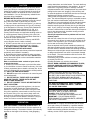
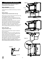
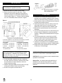
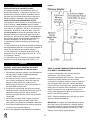
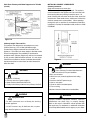
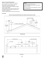
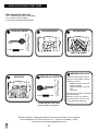
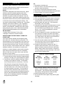
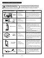
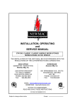
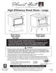
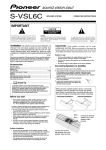
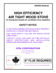
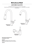
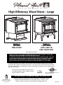
W a r m i n g Y o u r H o m e. W a r m i n g Y o u r H e a r t. High Efficiency Wood Stove - Large Model #: WS-3029 HWS-230292 Model #: LWS-130291 LWS-130291-B LWS-130291-BCA Save These Instructions. SAFETY NOTICE: IF THIS WOOD BURNING APPLIANCE IS NOT PROPERLY INSTALLED, OPERATED, AND MAINTAINED, A HOUSE FIRE MAY RESULT. TO REDUCE THE RISK OF FIRE, FOLLOW THE INSTALLATION INSTRUCTIONS. FAILURE TO FOLLOW THE INSTALLATION INSTRUCTIONS MAY RESULT IN PROPERTY DAMAGE, BODILY INJURY OR EVEN DEATH. CONTACT LOCAL BUILDING OFFICIALS ABOUT RESTRICTIONS AND INSTALLATION INSPECTION REQUIREMENTS IN YOUR AREA. This manual describes the installation and operation of the Model HWS-230292, Model WS-3029, and Model LWS-130291 non-catalytic wood heater. This heater meets US Environmental Protection Agency’s emission limits for wood heaters. Please read this entire manual before you install and use your new room heater. This stove is listed by OMNI-Test Laboratories of Portland, Oregon to meet UL1482 for the US and ULC-S627 for Canada. 6” Flue required TESTED TO: UL 1482-1996/ULC-S627-00 REPORT NO. 418-S-01-2 Do Not Discard This Manual: Retain for Future Use 8280 Austin Avenue Morton Grove, IL 60053 877-447-4768 Questions, problems, missing parts? Before returning to your retailer, call our customer service department at 877-447-4768 8:30 a.m. - 4:30 p.m. CST, Monday - Friday or e-mail us at [email protected]. 60-10-001 nearby obstructions, and other factors. Too much draft may cause excessive temperatures in the appliance. An uncontrolled burn or a glowing red part or chimney connector indicates excessive draft. Inadequate draft may cause back puffing into the room and “plugging” of the chimney and/ or cause the appliance to leak smoke into the room through appliance and chimney connector joints. Today’s solid fuel appliances are more efficient than in the past. The units are designed to give you controlled combustion, and maximum heat transfer, using less fuel to do so. The design of your new appliance is such that the exhaust smoke is now at lower temperatures than in the past, therefore requiring proper chimney size to give adequate draft. If your chimney is too large, the heating appliance will have a difficult time to raise the chimney flue temperature to give adequate draft, therefore causing a smoke back up, poor burn, or both. Should you experience such a problem call in a local chimney expert. With the door closed, the rate of burning is regulated by the amount of air allowed to enter the unit through the air control. With experience you will be able to set the control for heat and burning time desired. Once the required chimney draft is obtained, operate only with doors closed and open doors slowly when re-fueling. (This will reduce or eliminate smoke from entering the room). Attempts to achieve higher output rates that exceed heater design specifications can result in permanent damage to the heater. The recommended wood load is level with the top of the firebricks. Overloading may prevent sufficient air entering the heater to properly fuel the fire. Operate this heater only with the door closed. DO NOT BURN GARBAGE OR FLAMMABLE FLUIDS, SUCH AS GASOLINE, NAPHTHA, OR ENGINE OIL DO NOT USE CHEMICALS OR FLUIDS TO START THE FIRE. CAUTION After reading these instructions, if you have any doubt about your ability to complete your installation in a professional like manner you should obtain the services of an installer versed in all aspects as to the correct and safe installation. Do not use temporary makeshift compromises during installation. BEFORE INSTALLATION OF YOUR APPLIANCE 1. Check with the building inspector’s office for compliance with local codes; a permit may be required. 2. The room heater must be connected to 1) a chimney complying with the requirements for Type HT chimneys in the standard for Chimneys, Factory-Built, Residential Type and Building Heating Appliance, UL 103, or in Canada CAN/ULC-S629 Standard for 650 degree C Factory Built Chimneys and applicable building codes or 2) a code-approved masonry chimney with a flue liner. 3. A 6” (152mm) diameter, 24 gauge Black Steel flue is required for proper performance. 4. Always connect this unit to a chimney and NEVER vent to another room or inside a building. 5. DO NOT connect this unit to any duct work to which another appliance is connected such as a furnace. 6. DO NOT connect this unit to a chimney flue serving another appliance. 7. The connector pipe and chimney should be inspected periodically and cleaned if necessary. 8. Remember the clearance distances when you place furniture or other objects within the area. DO NOT store wood, flammable liquids or other combustible materials too close to the unit. Refer to certification label on back of your unit for required clearances. 9. Contact your local municipal or provincial fire authority for information on how to handle a chimney fire. Have a clearly understood plan to handle a chimney fire. In the event of a Chimney fire, turn air control to closed position and CALL THE FIRE DEPARTMENT. 10. DO NOT tamper with combustion air control beyond normal adjustment. 11. DO NOT install these units in a mobile home or trailer. These units are NOT mobile home approved. 12. DO NOT connect to ANY AIR DISTRIBUTION DUCT OR SYSTEM. 13. When installing a solid fuel appliance, it is also recommended to install Smoke and Carbon Monoxide Detectors on every level of the house. During the initial firing of the appliance, some smoke or odor may occur due to paint curing. You may want to keep some windows open for ventilation during the first few hours of burning to prevent smoke detector activation. Test your smoke and carbon monoxide detectors regularly. ALWAYS PROVIDE A SOURCE OF FRESH AIR INTO THE ROOM WHERE THE UNIT IS INSTALLED. FAILURE TO DO SO MAY RESULT IN AIR STARVATION OF OTHER FUEL BURNING APPLIANCES AND THE POSSIBLE DEVELOPMENT OF HAZARDOUS CONDITIONS. HOT WHILE IN OPERATION. KEEP CHILDREN, CLOTHING AND FURNITURE AWAY. CONTACT MAY CAUSE SKIN BURNS. OPTIONAL BLOWER: MODEL PBAR-2427, 120 VOLTS, 60Hz, 0.75 AMPS, 2900 RPM DANGER: RISK OF ELECTRIC SHOCK. DISCONNECT POWER BEFORE SERVICING UNIT. IMPORTANT: FOR OPTIMUM HEATER PERFORMANCE AT LOW BURN RATE, OPERATE THE FAN AT LOW SPEED. OPERATION IMPORTANT: It is highly recommended that the wood stove and chimney be installed by a qualified installer. (A qualified installer is a person or entity who regularly installs wood heating products and chimneys, in the ordinary course of their regular business.) WHY THE CORRECT FLUE SIZE IS IMPORTANT - 6” Draft is the force which moves air from the appliance up through the chimney. The amount of draft in your chimney depends on the length of the chimney, local geography, 1 Pedestal Base and Leg Installation Figure 0 Before Installing Stove, Follow These Steps for Pedestal Base and leg Installation. Model: HWS-230292 Large Wood Stove w/Pedestal Base ash pan Pedestal base is pre-installed at the factory. No action is required. Model: WS-3029 Large Wood Stove w/Pedestal Base and Legs Remove Ash pan and (4) bolts that secure the stove body to the pedestal as shown in Figure 0. With assistance, lift stove off of pedestal and lay stove on its side on a safe, elevated, padded and level platform that is about 6” off the ground. Using the bolts that were removed in step 1, bolt each leg to the bottom of the stove as shown in Figure 0.2. With assistance, lift the stove off of the raised platform, set upright on the legs, and re-install the ash pan. When stove is in place for installation, make sure stove is level by adjusting the leg levelers shown in Figure 0.3. Model: LWS-130291 Large Wood Stove w/Legs Remove ash pan and (4) bolts in angle iron bracket as shown in Figure 0.1. With assistance, lift stove off of wooden pallet and lay stove on its side on a safe, elevated, padded and level platform that is about 6” off the ground. Using the bolts that were removed in step 1, bolt each leg to the bottom of the stove as shown in Figure 0.2. With assistance, lift the stove off of the raised platform, set upright on the legs and re-install the ash pan. When stove is in place for installation, make sure stove is level by adjusting the leg levelers shown in Figure 0.3. Figure 0.2 Figure 0.3 leg leveler 2 INSTALLATION Figure 2 Contact your local building inspector prior to installation. A permit may be required in your area. 1. 2. Twist spring handle on in a clockwise motion. Spring handle will “thread” down to desired location. Remove all parts from inside the stove body. Select the proper location for the stove. These appliances must not be installed any closer than the minimum clearance to combustible materials shown in Brick pattern (Figure 1). The stove must be installed on a non combustible surface as shown in Figure 1. STOVE PIPE 1. A clearance of 18 inches (457mm) between the stovepipe and combustible materials may be required. Check with authorities having jurisdiction in your area. 2. All pipe sections must be connected with the male end (crimped end) toward the stove. 3. Fasten the stove pipe to the flue collar by the use of three sheet metal screws. Do the same at each additional joint to make the entire installation rigid. 4. Maintain the required diameter flue for the entire installation. 5. If you are connecting the stove to an old masonry flue, be sure to have it inspected for cracks and general condition. Resizing with a stainless steel liner may be required. 6. It is recommended that no more than two (2) 90° bends be used in the stove pipe installation. More than two (2) 90° bends may decrease the amount of draw and possibly cause smoke spillage. 7. A damper is not required in this installation. Remove damper plate in the chimney or secure in OPEN position. 8. Single wall flue pipe assemblies must not exceed 10 feet (3 m) in overall length. Figure 1 A minimum clearance of 18” (457 mm) to the chimney connector may be required by the authority having jurisdiction. From Heater From Chimney Connector A. Sidewall 22” (559 mm) D. Sidewall 32” (813 mm) B. Back Wall 16” (406 mm) E. Back Wall 19” (483 mm) C. Corner 12” (305 mm) F. Corner 21.5” (546 mm) Minimum height to ceiling 55” (1397 mm) *16” (406 mm) US **18” (457 mm) Canada Unit must be placed on a noncombustible floor protection equivalent to 1” millboard. Floor protector must have min. R value of 1.19. Consult your local building authorities for further information. 3. 4. 5. CAUTION: DO NOT open fire-door to a point where it would be in contact with the combustible sidewall. CAUTION: Brick for ash drawer must be installed before operation of wood heater. If noncombustible materials have been installed on the walls, obtain the minimum clearances from either the manufacturer of these materials or the local building inspectors office. Install the stovepipe INSIDE the flue collar on the top of the stove between the stove and chimney. DO NOT use a grate to elevate the fire. Optional Fan - An optional heat exchange blower is available for this wood burning appliance. To order please see the local dealer where you purchsed the appliance. 3 FLOOR PROTECTION Figure 3 INSTALLATION ON A CONCRETE FLOOR An appliance installed on a concrete floor does not require floor protection. If carpeting or any other combustible floor covering is installed, a clearance around the stove must be maintained equivalent to the size of the floor protector described in the following section. INSTALLATION ON A COMBUSTIBLE FLOOR If the appliance is to be installed on a combustible floor or floor covering, a floor protector must be inserted under the stove and project beyond the front of the stove a minimum of 16” (406mm) in the US or 18” (457mm) in Canada and 8”(203mm) on all other sides. In the US the floor protector must also be positioned under any horizontal chimney run and project beyond the pipe a minimum of 2” (51mm) on both sides. The floor protector must be a durable noncombustible material with a minimum thickness of 1.0” and an R value of “2”. To determine a material’s suitability use the following formulas; 1. If the material has an R (Thermal resistance) rating use the designated thickness and no conversion is needed. R values can be added for multi-layered materials. 2. If the material has a k (Thermal conductivity) rating convert this to an R rating using the formula R = 1/k x t (t = thickness in inches) 3. If the material has a C (Thermal conductance) rating convert this to an R rating using the formula R = 1/C. CHIMNEY CONTACT YOUR LOCAL BUILDING AUTHORITY FOR APPROVED METHODS OF INSTALLATION REFER TO CHIMNEY MANUFACTURER’S INSTRUCTIONS Flue Draft Considerations 1. This appliance requires a masonry or pre-manufactured chimney listed to CAN/ULC-S629 (Canada) and UL103HT (USA) sized correctly. 2. If a masonry chimney is used it is advisable to have your chimney inspected for cracks and check the general condition before you install your unit. Relining may be required to reduce flue diameter to the appropriate functional size. 3. To help ensure a good draft, the top of the chimney should be at least 3 feet (914mm) above the point of penetration through the roof, and be at least 2 (610mm) feet higher than any point of the roof within 10 feet (3M). 4. The chimney connector shall not pass through an attic, roof space, closet, concealed space, floor, ceiling, wall, or any partition of combustible construction. 5. The minimum overall height of your chimney should be 15 feet (5 m) from the floor (Figure 3). 6. Do not use makeshift compromises during installation. Location of the appliance and chimney will affect performance. The chimney should: • Penetrate the highest part of the roof. This minimizes the affects of wind turbulence and down drafts. • Consider the appliance location in order to avoid floor and ceiling attic joists and rafters. Exterior conditions such as roof line, surrounding trees, prevailing winds and nearby hills can influence stove performance. Your local dealer is the expert in your geographic area and can usually make suggestions or discover solutions that will easily correct your flue problem. NOTE: These are guidelines only, and may vary somewhat for individual installations. IMPORTANT: It is highly recommended that the wood stove and chimney be installed by a qualified installer. (A qualified installer is a person or entity who regularly installs wood heating products and chimneys, in the ordinary course of their regular business.) 4 Inspect Appliance & Components and Pre-Use Check List Venting Systems The venting system consists of a chimney connector (also known as stove pipe) and a chimney. These get extremely hot during use. Temperatures inside the chimney may exceed 2000°F (1100°C) in the event of a creosote fire. To protect against the possibility of a house fire, the chimney connector and chimney must be properly installed and maintained. An approved thimble must be used when a connection is made through a combustible wall to a chimney. A chimney support package must be used when a connection is made through the ceiling to a prefabricated chimney. These accessories are absolutely necessary to provide safe clearances to combustible wall and ceiling material. Follow venting manufacturer’s clearances when installing venting system. Tools And Supplies Needed Before beginning the installation be sure that the following tools and building supplies are available. Reciprocating saw Pliers Hammer Phillips Head Screwdriver Flat Blade Screwdriver Plumb Line Level Tape Measure Framing Material Hi-Temp Caulking Material Gloves Framing Square Electric Drill & Bits (1/4”) Safety Glasses 1/2 in. - /4 in. length, #6 or #8 self drilling screws (need per pipe section connection) 1. Place the appliance in a location near the final installation area and follow the procedures below: 2. Open the appliance and remove all the parts and articles packed inside the Component Pack. Inspect all the parts and glass for shipping damage. Contact your dealer if any irregularities are noticed. 3. All safety warnings have been read and followed. 4. This Owner’s Manual has been read. 5. Floor protection requirements have been met. 6. Venting is properly installed. 7. The proper clearances from the appliance and chimney to combustible materials have been met. 8. The masonry chimney is inspected by a professional and is clean, or the factory built metal chimney is installed according to manufacturer’s instructions and clearances. 9. The chimney meets the required minimum height. 10. All labels have been removed from the glass door. 11. A power outlet is available nearby if installing optional blower assembly. WARNING WARNING Fire Risk. Asphyxiation Risk. Inspect appliance and components for damage. Damaged parts may impair safe operation. • Do NOT install damaged components. • Do NOT install incomplete components. • Do NOT install substitute components. • Do NOT connect this unit to a chimney flue servicing another appliance. • Do NOT connect to any air distributon duct or system. May allow flue gases to enter the house. Report damaged parts to dealer. 5 Typical Stove Systems Stove system with masonry chimney consists of: • Stove • Chimney Connector (stove pipe) • Thimble • Masonry Chimney • Hearth Pad Floor Protection Figure 4.1 Masonry Chimney Stove system with prefabricated metal chimney consists of: • Stove • Chimney Connector (stove pipe) • Thimble (for exterior chimney) • Firestops • Insulations Shields • Storm Collar and Flashing • Termination Cap • Hearth Pad Floor Protection CHIMNEY REQUIREMENTS Figure 4.2 Exterior Prefabricated Chimney 6 Figure 4.3 Interior Prefab. Chimney Chimney Systems Prefabricated Metal Chimney • Must be a 6 inch (152mm) diameter (ID) high temperature chimney listed to UL 103HT (2100°F) or ULC S627. • Must use components required by the manufacturer for installation. • Must maintain clearances required by the manufacturer for installation. • Refer to manufacturers instructions for installation. CHIMNEY REQUIREMENTS Venting Components Chimney Connector: It is also known as flue pipe or stove pipe. The chimney connector joins the stove to the chimney. It must be a 6 inch (152mm) minimum diameter 24 gauge mild steel black steel, or an approved air-insulated double wall venting pipe. Thimble: A manufactured or site-constructed device installed in combustible walls through which the chimney connector passes to the chimney. It is intended to keep the walls from igniting. Site constructed thimbles must meet NFPA 211 Standards. Prefabricated must be suitable for use with selected chimney and meet UL103 Type HT Standards. Follow instructions provided by the manufacturer for manufactured thimbles for masonry chimney and prefabricated chimneys. Chimney: The chimney can be new or existing, masonry or prefabricated and must meet the following minimum requirements specified in Section 5B.B. NOTE: In Canada when using a factory-built chimney it must be safety listed, Type UL103 HT (2100°F) CLASS “A” or conforming to CAN/ULC-S629, STANDARD FOR 650°C FACTORY-BUILT CHIMNEYS. Figure 5.1 Prefabricated Exterior Chimney Figure 5.2 Prefabricated Interior Chimney 7 Thimble Site constructed for masonry chimney installation: Components • A minimum length of 12 inches [05mm] (longer for thicker walls) of solid insulated factory-built chimney length constructed to UL 103 Type HT 6 inch (152mm) inside diameter. Chimney needs to extend a minimum of 2 inches (51mm) from the interior wall and a minimum of 1 inch (25mm) from the exterior wall. • Wall spacer, trim collar and wall band to fit solid pack chimney selected. • Minimum 8 inch (20mm) diameter clay liner section (if not already present in chimney) and refractory mortar. Air Clearances • Masonry chimney clearance must meet NFPA 211 minimum requirement of 2 inches (51mm) to sheet metal supports and combustibles. • Minimum of 1 inch (25mm) clearance around the chimney connector. • Top of wall opening is a minimum of 1-1/2 inches (4mm) from ceiling or 4-1/2 inches (114mm) below minimum clearance specified by chimney connector manufacturer. NFPA 211 minimum vertical clearance of 18 inches (457mm) from chimney connector and ceiling or minimum recommended by chimney connector manufacturer. Figure 6.1. Instructions: 1. Open inside wall at proper height for the chimney connector to entry the masonry chimney. Figure 6.1. 2. Entry hole to masonry chimney must be lined with an 8 inch (20mm) minimum diameter clay liner, or equiva-lent, secured with refractory mortar. 3. Construct a 17 inch x 17 inch (42mm x 42mm) outside dimension frame from 2 x 2 framing lumber to fit into wall opening. Inside opening of frame should be no less than 14 inch x 14 inch (56mm x 56mm). Figure 6.1. 4. Attach the wall spacer to the chimney side of the frame. 5. Nail the frame into the wall opening. The spacer should be on the chimney side. 6. Insert the section of the solid insulated chimney into the outer wall of the masonry chimney. 7. Tightly secure the length of the solid insulated chimney with the wall band to the masonry chimney. 8. Insert a section of chimney connector into the chimney. Make sure it does not protrude past the edge of the clay chimney liner inside the chimney. 9. Seal the end of the chimney connector to the clay liner with refractory mortar. 10. Install trim collar around the sold pack chimney section. Figure 6.1 Solid Pack Chimney with Metal Supports as a Thimble Figure 7.1 WARNING Fire Risk. 8 Do NOT pack insulation or other combustibles between spacers. • ALWAYS maintain specified clearances around venting and spacers. • Install spacers as specified. Failure to keep insulation or other material away from vent pipe may cause fire. Solid Pack Chimney with Metal Supports as a Thimble (Cont’d) Installing Chimney Components Chimney Connector Single wall connector or stove pipe. This must be at least 24 gauge mild steel. The sections must be attached to the appliance and to each other with the crimped (male) end pointing toward the stove. All joints, including the connection at the flue collar, should be secured with sheet metal screws. Make sure to follow the minimum clearances to combustibles. Where passage through the wall, or partition of combustible construction is desired in Canada, the installation shall conform to CAN/ CSA-B365. Figure 7.2 Chimney Height / Rise and Run This product was designed for and tested on a 6 inch (152mm) chimney, 14 to 16 feet (420-480cm) high, (includes stove height) measured from the base of the appliance. The further your stack height or diameter varies from this configuration, the possibility of performance problems exists. Chimney height may need to be increased by 2% per each 1000 feet above sea level. It is not recommended to use offsets or elbows at altitudes above 4000 feet above sea level or when there are other factors that affect flue draft. Figure 8 WARNING Fire Risk. WARNING Follow Chimney Connector Manufacturer’s Instructions for Proper Installation. ONLY use connector: • Within the room, between appliance and ceiling or wall. Connector shall NOT pass through: • Attic or roof space • Closet or similar concealed space • Floor or ceiling Fire Risk. Inspection of Chimney: • Chimney must be in good condition. • Meets minimum standard of NFPA 211 • Factory-built chimney must be 6 inch (152mm) UL103HT. Maintain minimum clearances to combustibles WARNING WARNING Asphyxiation Risk. Improper installation, adjustment, alteration, service or maintenance can cause injury or property damage. Refer to the owner’s information manual provided with this appli-ance. For assistance or additional information consult a qualified installer, service agency or your dealer. • Do NOT connect this unit to a chimney flue servicing another appliance. • Do NOT connect to any air distributon duct or system. May allow flue gases to enter the house. 9 Chimney Termination Requirements Follow manufacturer’s instructions for clearance, securing flashing and terminating the chimney. • Must have an approved and listed cap • Must not be located where it will become plugged by snow or other material • Must terminate at least feet (91cm) above the roof and at least 2 feet (61cm) above any portion of the roof within 10 feet (05cm). • Must be located away from trees or other structures NOTE: • Chimney performance may vary. • Trees, buildings, roof lines and wind conditions affect performance. • Chimney height may need adjustment if smoking or overdraft occurs. 2-10-3 Rule These are safety requirements and are not meant to assure proper flue draft. 10 WOOD STOVE QUICK START GUIDE ITEMS NEEDED FOR FIRST FIRE: • 10 - 15 Wadded Up Pieces of Newspaper • 10 - 20 Pieces of Dry Kindling • A Few Pieces of Seasoned Split Wood OPEN AIR CONTROL CLOSE 2 ADD NEWSPAPER 3 ADD KINDLING OPEN LIGHT THE PAPER 6 WARNING! Risk of Fire 4 ADD WOOD 5 REDUCE AIR CONTROL Close and securely latch the door after the fire has started, and after refueling, to prevent: • Spillage of smoke, flame and carbon monoxide • Spillage of sparks, coals and logs • Over-firing CLOSE OPEN LINCOLN LOG METHOD DO NOT leave the stove unattended with the door open. Starting a fire may not require an open door to draft. The air control should supply adequate draft. Congratulations! Your wood stove is ready for operation. Questions, problems, missing parts? Before returning to your retailer, call our customer service department at 877-447-4768 8:30 a.m. –4:30 pm CST, Monday – Friday. or email us at [email protected] 11 OPERATION SO: 1. Remember to Ventilate well. 2. Allow the stove to cure before burning for long periods at high temperatures. 3. Flat spots on the painted surfaces are normal. 4. Shiny spots on the paint surface before burning is normal. 5. Call your dealer if you have any questions. Do not use a grate or elevate fire. Build wood fire directly on hearth. When the stove is used for the first time the solvents in the paint will smoke off. WOOD This heater is designed to burn natural wood only. Higher efficiency and lower emissions generally result when burning air dried seasoned hardwood, as compared to softwood or to green or freshly cut hardwood. Only use dry seasoned wood. Green wood, besides burning at only 60 percent of the fuel value of dry wood, deposits creosote on the inside of your stove and along the chimney. This can cause an extreme danger of chimney fire. To be called seasoned, wood must be dried for a year. Regardless of whether the wood is green or seasoned, it should be stored in a well-sheltered, ventilated area to allow proper drying during the year to come. Wood should be stored beyond recommended clearance from combustibles. DO NOT BURN: • Treated Wood • Solvents • Trash • Coal • Garbage • Cardboard • Coloured Papers INSTRUCTIONS FOR FIRST BURN - CURING THE STOVE PAINT Your stove has been painted with the highest quality stove paint and has special break-in procedures. The heat generated by the normal operation of the stove, will serve to harden the paint.Ventilate the house during the first three times the stove is used. The paint on the stove will give off smoke, carbon dioxide and an odor. Without adequate ventilation, concentrations of smoke could irritate you or cause damage to person and/or property. Open doors and windows and use a fan if necessary. After the initial burns, the paint will be cured and there should be no more smoke. Each of the initial burns should be conducted as follows: 1. The first and second burns should be at approximately 250 deg F (120 deg C) for approximately 20 minutes. 2. The third burn should be between 500 deg F (260 to 370 deg C) for at least 45 minutes. The important fact is the paint should be cured slowly. Avoid hot fires during the curing process. During the curing process the paint will be gummy. Once cured the paint will remain hard. It is normal to see flat spots on painted surfaces of the stove. The flat spots on the paint surface indicate the hotter surfaces of the stove, and is caused by the heat radiating through the paint. It is also expected that shiny spots caused by friction from the packaging materials, will disappear during the curing of the stove. BUILDING A FIRE 1. 2. 3. 4. 5. Open inlet air control fully. Place a small amount of crumpled paper in the stove. Cover the paper with a generous amount of kindling in a teepee fashion and a few small pieces of wood. Ignite the paper and close door. If fire dies down substantially, open door slightly. Using the lincoln log method, add larger pieces of wood as the fire progresses being careful not to overload. Do not fill firebox beyond firebrick area. An ideal coal bed of 1” to 2” should be established to achieve optimum performance. 6. This unit is designed to function most effectively when air is allowed to circulate to all areas of the firebox. An ideal means of achieving this is to rake a slight (1” to 2” wide) trough in the centre of the coal bed from front to back prior to loading the fuel. 7. Once fuel has been loaded, close door and open air inlet control fully until fire is well established (approx. 10 minutes) being careful not to overfire. 8. Readjust air inlet control to desired burn rate. If excessive smoke fills firebox, open air inlet control slightly until flames resume and wood is sufficiently ignited. While a basic rule of thumb is “closed-low”, 1”/2 way-medium” and “fully open-high”, refer to the Inlet Air Control Settings chart. Inlet Air Control Settings Desired Burn Setting Inlet Air Setting **Approx. BTU Output Low Med/Low Med/High High Closed Fully 1/4 Open 3/4 Open Fully Open 12,000 15,000 19,000 35,000 9. When refuelling, adjust air control to the fully open position. When fire brightens, slowly and carefully open the door. This procedure will prevent gases from igniting causing smoke and flame spillage. 10. Add fuel being careful not to overload. 11. Do not build fire close to glass. May result in glass breakage. 12 NEVER USE GASOLINE, GASOLINE-TYPE LANTERN FUEL, KEROSENE, CHARCOAL LIGHTER FLUID, OR SIMILAR LIQUIDS TO START OR FRESHEN UP A FIRE IN THIS HEATER. KEEP ALL SUCH LIQUIDS WELL AWAY FROM THE HEATER WHILE IT IS IN USE. burn improperly.) 5. Attach glass gasket (from GHP Group replacement parts page 18) to new glass and install in door frame. 6. Replace glass retainers with screws making sure not to cross thread or overtighten. 7. Place door on hinges and replace new push nuts, purchased from GHP Group, on door pins to ensure door does not move after reinstall. GLASS CARE The following use and safety tips should be observed: 1. Inspect the glass regularly for cracks and breaks. If you detect a crack or break, extinguish the fire immediately, and contact your dealer for replacement. 2. Do not slam door or otherwise impact the glass. When closing doors, make sure that logs or other objects to not protrude and impact the glass. 3. Do not clean the glass with materials which may scratch (or otherwise damage) the glass. Scratches on the glass can develop into cracks or breaks. 4. Never attempt to clean the glass while unit is hot. If the deposit is not very heavy, normal glass cleaners are adequate with a plain, non-abrasive scouring pad. Heavier deposits may be removed with the use of a readily available oven cleaner. 5. Never put substances which can ignite explosively in the unit since even small explosions in confined areas can blow out the glass. 6. This unit has an airwash system, designed to reduce deposits on glass. 7. Deposits may build on the glass during normal operation and use. Normal glass cleaners work well to remove these deposits. Heavier deposits may be removed by using a damp cloth dipped in wood ashes or by using a commercially available oven cleaner. GASKET REPLACEMENT GASKET REPLACEMENT After extensive use, the sealing material which provides glass and door seal may need to be replaced if it fails to sustain its resilience. Inspect glass and door seal periodically to ensure for proper seal. If gaskets become frayed or worn, replace immediately. Contact your dealer or GHP Group Customer Service for approved replacement parts. The following steps should be followed for glass gasket replacement: 1. Ensure appliance is not in operation and is thoroughly cooled. 2. Remove screw and glass clip. 3. Lift glass out from glass clip. 4. Remove old gasket and clean glass. 5. Replace new gasket starting at the bottom of glass working along edges, being sure to centre gasket channel on glass. 6. Trim to length and butt ends together. 7. Replace glass in door, being sure not to over-tighten screw and clip. The following steps should be followed for door gasket replacement: 1. Ensure appliance is not in operation and is thoroughly cooled. 2. Remove old door gasket and clean channel. 3. Using an approved high temperature gasket cement, apply a thin coat in bottom of channel. 4. Starting at hinge side of door, work into channel around door unit, end butt and trim to length. 5. Close door and allow three to four hours for cement to set before restarting appliance. REPLACE GLASS ONLY WITH GHP GROUP 5MM CERAMIC GLASS (SEE REPLACEMENT PARTS PAGE 18). GLASS REPLACEMENT CREOSOTE CREOSOTE CAUTION: Make sure fire is out and stove is completely cool to the touch. Creosote - Formation and Need for Removal When wood is burned slowly, it produces tar and other organic vapors, which combine with expelled moisture to form creosote. The creosote vapors condense in the relatively cool chimney flue of a slow-burning fire. As a result, creosote residue accumulates on the flue lining. When ignited this creosote makes an extremely hot fire. 1. Find an area that will ensure safe removal and no damage to surface of door frame or decorative home furnishing. 2. Wearing a pair of protective gloves, remove the push nuts that retain the door pins from being pulled out and then lift the door off of the hinges. 3. Lay the door face down on a protective surface located in Step 2. 4. Remove the screws from all glass retainers and remove the broken glass, ensuring that the door frame is free from any slivers. (If even small slivers are left, the new glass will not seal correctly causing the stove to The chimney connector and chimney should be inspected at least once every two months during the heating season to determine if a creosote buildup has occurred. If creosote has accumulated (3 mm or more) it should be removed to reduce the risk of a chimney fire. WAYS TO PREVENT AND KEEP UNIT FREE OF 13 USING THE ASH DRAWER CREOSOTE 1. Burn with air control open for several minutes at numerous intervals throughout the day during the heating season, being careful not to over-fire unit. This removes the slight film of creosote accumulated during low burn periods. 2. Burn stove with draft control wide open for several minutes every time you apply fresh wood. This allows wood to achieve the charcoal stage faster and burns wood vapours which might otherwise be deposited within the system. 3. BURN ONLY SEASONED WOOD. Avoid burning wet or green wood. Seasoned wood has been dried for at least one year. 4. A small hot fire is preferable to a large smouldering one that can deposit creosote within the system. 5. Establish a routine for the fuel, wood burner and firing technique. Check daily for creosote build-up until experience shows how often you need to clean to be safe. Be aware that the hotter the fire, the less cresote is deposited and weekly cleanings may be necesary in mild weather even though monthly cleanings may be enough in the coldest months. Contact your local municipal authority for information on how to handle a chimney fire. Have a clearly understood plan to handle a chimney fire. NOTE: Coals may still be hot even though stove feels cool to the touch. 1. Make sure stove is completely cool. 2. Open glass door and lift up the firebrick for ash drawer using a fireplace poker through the metal hook raised from the top of the brick and set aside in firebox. 3. Using a small hand broom, sweep the ashes into the opening, allowing the ashes to fall into the ash pan. 4. Make sure all debris is clear of the opening. This is important to ensure the firebrick (when replaced) seals to the metal stove bottom. If the fire brick is not properly sealed, the stove will not operate correctly. 5. Using gloves, pull out the ash drawer while holding the bottom of the ash pan so it doesn’t fall out onto the floor. 6. Dispose of the ashes in a metal container with a tight-fitting lid. 7. Replace ash pan drawer and firebrick to their original positions. HELPFUL HINTS WARNING: Things to remember in case of chimney fire: 1. CLOSE DRAFT CONTROL. 2. CALL THE FIRE DEPARTMENT. IMPORTANT IMPORTANT 1. What is the correct way to start a fire? a) You will need small pieces of dry wood (kindling) and paper. Use only newspaper or paper that has not been coated or had unknown materials glued or applied to it. Never use coated (typically advertising flyers) or coloured paper. b) Open the door of the wood stove. c) Crumple several pieces of paper and place them in the center of the firebox and directly on to the fire bricks of the wood stove. Never use a grate to elevate the fire. d) Place small pieces of dry wood (kindling) over the paper in a Teepee manner. This allows for good air circulation, which is critical for good combustion. e) Light the crumpled paper in 2 or 3 locations. Note: It is important to heat the air in the stovepipe for draft to start. f) Fully open the air control of the wood stove and close the door until it is slightly open, allowing for much needed air to be introduced into the fire box. Never leave the door fully open as sparks from the kindling may occur causing injury or property damage. As the fire begins to burn the kindling, some additional kindling may be needed to sustain the fire. DO NOT add more paper after the fire has started. ASH DISPOSAL This unit features a convenient ash lip for easy removal of ash. During constant use, ashes should be removed every few days, or whenever ashes get to three to four inches deep in the firebox. Remove ashes only when the fire has died down and the ashes have cooled. Even then, expect to find a few hot embers. Disposal of Ashes: Ashes should be placed in a steel container with a tightfitting lid. The container of ashes should be moved outdoors immediately and placed on a noncombustible floor or on the ground, well away from combustible materials, pending final disposal. If the ashes are disposed of by burial in soil or otherwise locally dispersed, they should be retained in the closed container until all cinders have thoroughly cooled. Other waste shall not be placed in this container. 14 2. 3. 4. 5. two years will be difficult to ignite, if it has become wet. 6. Why is there always a large quantity of thick black smoke present in the firebox? A large quantity of thick black smoke in the firebox, is a good indication that the draft is poor. 7. Is it normal for soot to cover the glass at the beginning of a fire? Your stove has been built with an air wash system that will help keep the glass clear when the firebox has reached a good operating temperature, and has a good draft. Cold firebox temperature and poor draft cause sooting of the glass. Once the firebox tempera ture and the draft increases, the soot will burn off. 8. What is draft? Draft is the ability of the chimney to exhaust draw by products produced during the normal combustion process. 9. What can cause a poor draft? The most common factors for poor draft are: a) Atmospheric pressure and air supply b) Environmental conditions c) Cold chimney temperature d) Poor chimney installation and maintenancea) Atmospheric Pressure and Air Supply Atmospheric pressure affecting the draft from a chimney can be either outside the home, inside the home or both. Outside the home, a high-pressure day (clear and cool) generally creates a better draft in the chimney than a low-pressure day (overcast and damp). Inside the home, normal household appliances, such as clothes dryers and forced air furnaces compete for air resulting in inadequate amounts of air available to fuel a fire and create a condition known as negative pressure. Under extreme conditions of negative pressure the combustion by-products can be drawn from the chimney and into the house. This condition is commonly referred to as down drafting. There are several factors that impact the amount of air available in the home. Increased amounts of insulation vinyl windows, extra caulking in various places and door seals can all keep heat in but may also make a home too airtight. If you are in doubt about whether or not there is sufficient air in your home for your stove, refrain from using those appliances known to consume the air where possible, or open a window or door to allow air to enter the home. g) Once the kindling has started to burn, start by adding some of your smaller pieces of seasoned (dry) firewood. Note: Adding large pieces at the early stages will only serve to smother the fire. Continue adding small pieces of seasoned (dry) firewood, keeping the door slightly open until each piece starts to ignite. Remember to always open the door slowly between placing wood into the fire. h) Once the wood has started to ignite and the smoke has reduced, close the wood stove door fully. The reduction of smoke, is a good indication that the draft in the chimney has started and good combustion is now possible. Larger pieces of seasoned (dry) fire wood can now be added when there is sufficient space in the Firebox. Adjust the air control setting to desired setting. I) Note: The lower the air control setting the longer the burn time of your firewood. What type of wood is best to use as Firewood? Dry seasoned hardwood should be used. Avoid green unseasoned wood. Green wood, besides burning at only 60 percent of the fuel value of dry seasoned wood, will deposit creosote on the inside of your stove and along the inside of your chimney. What does dry seasoned wood mean, and what is considered hardwood? Wood that has been dried for a period of one year in a well-ventilated and sheltered area would be considered dry seasoned wood. Hardwoods are generally from slow growth trees (Example: Oak and Fir). Softwoods are generally from fast growth trees. (Example: Pine and Spruce) Will following the above listed steps for starting a fire result in perfect results all the time? The quick answer is most of the time. There are many variables that may affect your success rate when staring a fire. Most of those variables and how to deal with them will be learned through experience. Your ability to start a good fire will significantly increase with time and patience. Some of the reasons for poor stove performance will be covered in the next section of these instructions. Why can’t I get the fire lit? Damp or wet wood and poor draft are the main reasons for poor results in starting a fire. Always use dry seasoned wood for your fire. Even wood dried for 15 Environmental Conditions High trees, low lying house location such as in a valley, tall buildings or structures surrounding your house and windy conditions can cause pool draft or down drafting. Cold Chimney Temperature Avoid cold chimney temperatures by burning a hot fire for the first fifteen to forty minutes, being careful not to over fire. If any part of the chimney or parts of the stove start to glow, you are over firing the stove. Where possible, install a temperature gauge on the chimney so temperature drops can be seen. Chimney Installation and Maintenance Avoid using too many elbows or long horizontal runs. If in doubt, contact a chimney expert and/or chimney manufacturer for help. Clean chimney, rain caps and especially spark arrester regularly, to prevent creo sote build-up, which will significantly reduce chimney draw and may cause a chimney fire. 10. Should I close or open the air control fully when shutting down the stove? When shutting down the stove, fully open the air control. This allows the chimney temperatures to remain as high as possible for as long as possible. Cold chimney temperatures create creosote. Note: This sheet is intended as an aid and does not supersede any local, provincial or state requirements. Check with officials or authorities having jurisdiction in your area. 16 QUICK REFERENCE MAINTENANCE GUIDE CAUTION! Allow the appliance to completely cool down before performing any cleaning or maintenance. AreA OF MAINTENANCE Start the first inspection after the first 2 months of use, or if performance changes, and adjust your schedule accordingly. Maintenance is required for safe operation and must be performed to maintain your warranty. Frequency Baffle & Blanket MONTHLY or After Every Cord of Wood Baffle and blanket placement is critical to heat output, efficiency and overall life of the unit. Make sure the baffle is pushed all of the way to the back of the firebox and the blanket is laying flat. Inspect baffle for cracks. Optional Blower YEARLY or After Every 4 Cords of Wood Vacuum the blower impellers. Rear Front TASK Baffle Chimney System Firebrick & Ash Removal Door & Glass Assemblies EVERY 2 MONTHS or After Every 4 Cords of Wood WEEKLY or After Every 25 Loads of Wood WEEKLY or After Every 25 Loads of Wood The chimney and chimney cap must be inspected for soot and creosote every two months during the burn season or more frequency if chimney exceeds or is under 14-16 ft (4.3m- 4.8m) measured from bottom of appliance. This will prevent pipe blockage, poor draft, and chimney fires. Always burn dry wood to help prevent cap blockage and creosote build-up. Ashes must be cool before you can dispose of the ashes in a non-combustible container. Firebrick is designed to protect your firebox. After ashes are removed, inspect the firebrick and replace firebricks that are crumbling, cracked or broken. Keep door and glass gasket in good shape to maintain good burn times on a low burn setting. To test: place a dollar bill between the stove and door and then shut the door. If you can pull the dollar out, replace the door gasket. Check the glass frame for loose screws to prevent air leakage. Check glass for cracks. Latch Cam Door Handle WEEKLY or After Every 25 Loads of Wood 17 Check the door latch for proper adjustment. This is very important especially after the door rope has formed to the stove face. Check door handle for smooth cam operation. Brick Pattern GHP Group reserves the right to make changes in design, materials, specifications, prices and discontinue colors and products at any time, without notice. Item No. Description Qty. 1. Door Assembly 2. & 3. Glass (13.00”W x 8.38”H) and Gasket 3. 1/8” Glass Gasket 4. 5/8” Door Gasket 5. Spring Handle 6. Air Control Spring Handle 7. Glass Clip 8.Screw 9. Hinge Pin 10. Push Nut 11. Firebrick Lt. 7 3/4” x 4 7/16” x 1 1/4” 12. Firebrick Lt. 9” x 4 7/16” x 1 1/4” 13. Firebrick Lt. 4 1/2” x 4 7/16” x 1 1/4” 14. Firebrick Lt. 9” x 2 1/2” x 1 1/4” 15. Firebrick for Ash Drawer 16. Ash Drawer Assembly 17. Leg Assembly 18 Part No. 1 75-21-503 1 75-21-514 4.3’ 75-21-123 5.1’ 75-21-143 1 75-20-140 1 75-20-141 6 75-25-131 675-21-141 2 75-20-132 2 75-21-150 4 75-21-145 15 75-21-147 1 75-21-146 1 75-21-148 1 75-21-149 1 75-21-512 4 75-22-510 5 Year Warranty GHP Group warrants that your new woodburning stove or masonry wood insert is free from manufacturing and material defects for a period of five years from the date of sale, subject to the following conditions and limitations. 1. This warranty is extended to the original owner only, for residential use, and is subject to proof of purchase. 2. The new GHP Group product must be installed and operated at all times in accordance with the installation and operation instructions supplied with the appliance, and installation must be to local and national codes. Any alterations, willful abuse, accident, over firing or misuse will not be coverd under warranty. NOTE: Some minor movement of certain parts is normal and is not a defect and therefore, not covered under warranty. 3. The warranty is non-transferable, and is made to the original owner, provided that the purchase was made through an authorized GHP Group supplier. The serial number must be supplied along with the Bill of Sale, showing the date of purchase, at the time the claim is submitted. 4. This warranty is limited to the repair or replacement of parts only, found to be defective in material or construction, provided that such parts have been subjected to normal conditions of use and service, after a said defect has been confirmed by GHP Group, or an authorized representative’s inspection. Defective parts must be shipped back (at GHP Group discretion), transportation prepaid, to the manufacturer. Credits will be issued upon receipt of return of the defective product to GHP Group. 5. GHP Group, at its discretion, can fully discharge all obligation with respect to this warranty by refunding the wholesale price of the defective part(s). 6. Any installation, labor, construction, transportation or other related costs or expenses arising from defective parts, repair, replacement or otherwise of same, will not be covered by this warranty nor will GHP Group assume responsibility for same. Further, GHP Group will not be responsible for any incidental, indirect or consequent damages, except as provided by law, and in no event shall they exceed the original purchase price. 7. All other warranties - expressed or implied - with respect to the product, its components and accessories, or any obligations/liabilities on the part of GHP Group are hereby expressly excluded. 8. GHP Group neither assumes, nor authorizes any third party to assume, on GHP Group’s behalf, any other liabilities with respect to the sale of this GHP Group product. 9. The warranties as outlined within this document do not apply to chimney components or other products made by other manufacturers when used in conjunction with the installation of this product. Improper use or the use of non-approved components may nullify your warranty. If in doubt, contact your nearest GHP Group supplier or GHP Group Customer Service Department. 10. GHP Group will not be responsible for: • Downdrafts or spillage caused by environmental conditions such as nearby trees, buildings, rooftops, hills, mountains, or ineffective chimney design. • Inadequate ventilation, excessive offsets or negative air pressure caused by mechanical systems such as furnaces, clothes dryers, fans, etc. 11. This warranty is void if: • The appliance has been operated in atmospheres contami- nated by chlorine, fluorine, or other damaging chemicals. • This appliance has been subjected to prolonged periods of dampness or condensation. • The appliance has any damage due to water, or weather damage that is the result of, but not limited to, improper chimney/venting installation. • The appliance has been subjected to willfull or accidental abuse or misuse. • Corrosive driftwood, manufactured logs or other fuels are used other than as outlined in the installation and operating instructions. • The appliance is not maintained in good condition, including firebrick and gaskets. Doors with Glass and Plated Parts Glass is warranted against thermal breakage only. To clean glass, use a ceramic/glass cleaner or polish. Do not use ammonia based cleaners. A suitable cleaner is available at your nearest Pleasant Hearth dealer. DO NOT CLEAN GLASS WHILE HOT AND DO NOT USE ABRASIVE CLEANERS. Plated parts will not be covered under this warranty. Plated parts should be cleaned by using denatured alcohol only and rubbed lightly with a lint-free non-abrasive cloth. Excessive rubbing or polishing may remove the plated finish. Plated parts may also be damaged by external chemicals. Further Exclusions This warranty will not include or extend to paint, gaskets or firebrick components, and does not cover any removable firebox components such as brick retainers or stainless steel air tubes. Electrical Components GHP Group warranty coverage extends to electrical components (e.g. blowers, speed controls) also. IF WARRANTY SERVICE IS REQUIRED Contact GHP Group Customer Service. Make sure you have your sales receipt and the model/serial number of your GHP Group product. Do not attempt to do any service work yourself, unless preapproved by GHP Group in writing as this will void the warranty. GHP Group must authorize service and provide a Warranty Claim Number prior to any warranty related service calls. Without an authorization number, any service work will not be deemed warranty. IMPORTANT NOTICE BEFORE LIGHTING YOUR FIRST FIRE, REMOVE PLASTIC FILM OFF TRIM AND CLEAN THE PLATED SURFACES WITH DENATURED ALCOHOL OR A GOOD QUALITY, NONABRASIVE LIQUID GLASS CLEANER. APPLY WITH A VERY SOFT, CLEAN CLOTH. DO NOT USE PAPER TOWELS TO CLEAN THE PLATED PARTS. FAILURE TO CLEAN ALL MARKS AND FINGERPRINTS FROM THE PLATED SURFACES WILL CAUSE PERMANENT DAMAGE. NOTE: Some states and provinces do not allow the exclusion or limitation of incidental or consequential damages. The above limitations may not apply to you. GHP Group, Inc. • 8280 Austin Ave. • Morton Grove, IL 60053 KEEP THIS WARRANTY Serial #_______________________________ Model #________________________ Date Purchased________________________ 19