1
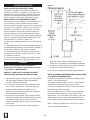
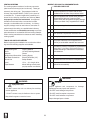
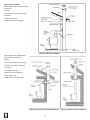
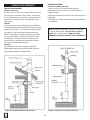
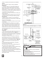
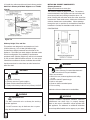
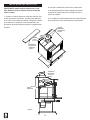
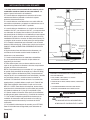
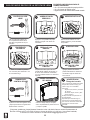
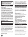
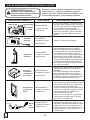
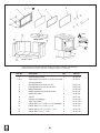
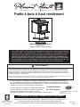
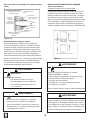
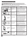
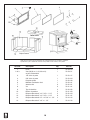
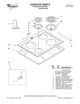
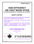
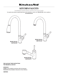
W a r m i n g Y o u r H o m e. W a r m i n g Y o u r H e a r t. High Efficiency Wood Stove - Small Model Series: HWS-224172MH HWS-224172 LWS-124171 (Mobile Home Approved) SAFETY NOTICE: IF THIS WOOD BURNING APPLIANCE IS NOT PROPERLY INSTALLED, OPERATED, AND MAINTAINED, A HOUSE FIRE MAY RESULT. TO REDUCE THE RISK OF FIRE, FOLLOW THE INSTALLATION INSTRUCTIONS. FAILURE TO FOLLOW THE INSTALLATION INSTRUCTIONS MAY RESULT IN PROPERTY DAMAGE, BODILY INJURY OR EVEN DEATH. CONTACT LOCAL BUILDING OFFICIALS ABOUT RESTRICTIONS AND INSTALLATION INSPECTION REQUIREMENTS IN YOUR AREA. WARNING BEFORE LIGHTING YOUR FIRST FIRE, REMOVE PLASTIC FILM OFF TRIM AND CLEAN THE PLATED SURFACES WITH DENATURED ALCOHOL OR A GOOD QUALITY, NON-ABRASIVE LIQUID GLASS CLEANER. APPLY WITH A VERY SOFT, CLEAN CLOTH. DO NOT USE PAPER TOWELS TO CLEAN THE PLATED PARTS. FAILURE TO CLEAN ALL MARKS AND FINGERPRINTS FROM THE PLATED SURFACES WILL CAUSE PERMANENT DAMAGE. NOTE: Some states and provinces do not allow the exclusion or limitation of incidental or consequential damages. The above limitations may not apply to you. This manual describes the installation and operation of the Model HWS-224172MH, non-catalytic wood heater. This heater meets US Environmental Protection Agency’s emission limits for wood heaters. Please read this entire manual before you install and use your new room heater. This stove is listed by OMNI-Test Laboratories of Portland, Oregon to meet UL1482 for the US and ULC-S627 for Canada. (UM) 84 HUD, mobile home approved (Excluding model WS-2417). 6” Flue required TESTED TO: UL 1482-1996/ULC-S627-00 REPORT NO. 418-S-03-2 Do Not Discard This Manual: Retain for Future Use 6440 W. Howard St. Niles, IL 60714-3302 877-447-4768 Questions, problems, missing parts? Before returning to your retailer, call our customer service department at 877-447-4768 8:30 a.m. - 4:30 p.m. CST, Monday - Friday or e-mail us at [email protected]. 60-10-002 07/14 through the chimney. The amount of draft in your chimney depends on the length of the chimney, local geography, nearby obstructions, and other factors. Too much draft may cause excessive temperatures in the appliance. An uncontrolled burn or a glowing red part or chimney connector indicates excessive draft. Inadequate draft may cause back puffing into the room and “plugging” of the chimney and/or cause the appliance to leak smoke into the room through appliance and chimney connector joints. Today’s solid fuel appliances are more efficient than in the past. The units are designed to give you controlled combustion, and maximum heat transfer, using less fuel to do so. The design of your new appliance is such that the exhaust smoke is now at lower temperatures than in the past, therefore requiring proper chimney size to give adequate draft. If your chimney is too large, the heating appliance will have a difficult time to raise the chimney flue temperature to give adequate draft, therefore causing a smoke back up, poor burn, or both. Should you experience such a problem call in a local chimney expert. With the door closed, the rate of burning is regulated by the amount of air allowed to enter the unit through the air control. With experience you will be able to set the control for heat and burning time desired. Once the required chimney draft is obtained, operate only with doors closed and open doors slowly when re-fueling. (This will reduce or eliminate smoke from entering the room). Attempts to achieve higher output rates that exceed heater design specifications can result in permanent damage to the heater. The recommended wood load is level with the top of the firebricks. Overloading may prevent sufficient air entering the heater to properly fuel the fire. Operate this heater only with the door closed. DO NOT BURN GARBAGE OR FLAMMABLE FLUIDS, SUCH AS GASOLINE, NAPHTHA, OR ENGINE OIL DO NOT USE CHEMICALS OR FLUIDS TO START THE FIRE. CAUTION After reading these instructions, if you have any doubt about your ability to complete your installation in a professional like manner you should obtain the services of an installer versed in all aspects as to the correct and safe installation. Do not use temporary makeshift compromises during installation. BEFORE INSTALLATION OF YOUR APPLIANCE 1. Check with the building inspector’s office for compliance with local codes; a permit may be required. 2. The room heater must be connected to 1) a chimney complying with the requirements for Type HT chimneys in the standard for Chimneys, Factory-Built, Residential Type and Building Heating Appliance, UL 103, or in Canada CAN/ULC-S629 Standard for 650 degree C Factory Built Chimneys and applicable building codes or 2) a code-approved masonry chimney with a flue liner. 3. A 6” (152mm) diameter, 24 gauge Black Steel flue is required for proper performance. 4. Always connect this unit to a chimney and NEVER vent to another room or inside a building. 5. DO NOT connect this unit to any duct work to which another appliance is connected such as a furnace. 6. DO NOT CONNECT THIS UNIT TO A CHIMNEY FLUE SERVING ANOTHER APPLIANCE. 7. The connector pipe and chimney should be inspected periodically and cleaned if necessary. 8. Remember the clearance distances when you place furniture or other objects within the area. DO NOT store wood, flammable liquids or other combustible materials too close to the unit. Refer to certification label on back of your unit for required clearances. 9. Contact your local municipal or provincial fire authority for information on how to handle a chimney fire. Have a clearly understood plan to handle a chimney fire. In the event of a Chimney fire, turn air control to closed position and CALL THE FIRE DEPARTMENT. 10. DO NOT tamper with combustion air control beyond normal adjustment. 11. DO NOT CONNECT TO ANY AIR DISTRIBUTION DUCT OR SYSTEM. 12. When installing a solid fuel appliance, it is also recommended to install Smoke and Carbon Monoxide Detectors on every level of the house. During the initial firing of the appliance, some smoke or odor may occur due to paint curing. You may want to keep some windows open for ventilation during the first few hours of burning to prevent smoke detector activation. Test your smoke and carbon monoxide detectors regularly. IMPORTANT: It is highly recommended that the wood stove and chimney be installed by a qualified installer. (A qualified installer is a person or entity who regularly installs wood heating products and chimneys, in the ordinary course of their regular business.) ALWAYS PROVIDE A SOURCE OF FRESH AIR INTO THE ROOM WHERE THE UNIT IS INSTALLED. FAILURE TO DO SO MAY RESULT IN AIR STARVATION OF OTHER FUEL BURNING APPLIANCES AND THE POSSIBLE DEVELOPMENT OF HAZARDOUS CONDITIONS. OPERATION HOT WHILE IN OPERATION. KEEP CHILDREN, CLOTHING AND FURNITURE AWAY. CONTACT MAY CAUSE SKIN BURNS. WHY THE CORRECT FLUE SIZE IS IMPORTANT - 6” Draft is the force which moves air from the appliance up 1 • Electric screw driver with bits • Silicone sealant • Drills and saws necessary for cutting holes through the wall or flooring in your home OPTIONAL BLOWER: MODEL PBAR-2427, 120 VOLTS, 60Hz, 1.0 AMPS, 2900 RPM DANGER: RISK OF ELECTRIC SHOCK. DISCONNECT POWER BEFORE SERVICING UNIT. IMPORTANT: FOR OPTIMUM HEATER PERFORMANCE AT LOW BURN RATE, OPERATE THE FAN AT LOW SPEED. AN OUTSIDE AIR KIT (ITEM NO: OAK-MH) IS AVAILABLE FOR PURCHASE BY CALLING GHP GROUP CUSTOMER SERVICE AT 1-877-447-4768. 1. Remove all materials from packing boxes. 2. Floor & Rear Installation: Cut a 4 inch (102mm) hole in outside wall or floor to accommodate outside air piping. Use 4 inch (102mm) aluminum metal flex or rigid piping to directly connect outside air to appliance intake. Use a termination cap with a rodent screen. Seal between the wall (or floor) and the pipe with silicone to prevent moisture penetration. 3. Using a #2 Phillips screw driver attach the flex pipe to the flex adaptor on the stove using a pipe clamp. Figure 00. For installation information on optional blower PBAR-2427, please refer to the Wood Stove Blower Installation and Operating Instructions supplied with the blower. MOBILE HOME APPROVED This appliance, excluding Model # WS-2417 is approved for mobile home installations when not installed in a sleeping room and when an outside combustion air inlet is provided. The structural integrity of the mobile home floor, ceiling, and walls must be maintained. The appliance must be properly grounded to the frame of the mobile home and use only listed double-wall connector pipe. An Outside Air Kit must be installed in a mobile home installation. WARNING NOTE: This installation must conform with local codes. In the absence of local codes you must comply with the UL1482, (UM) 84-HUD and NPFA211 in the U.S.A. and the CAN/ULC-S629 and CAN/CSA-B365 Installation Codes in Canada. OUTSIDE AIR KIT INSTALLATION A source of air (oxygen) is necessary in order for combustion to take place. Whatever combustion air is consumed by the fire must be replaced. Air is replaced via air leakage around windows and under doors. In homes that have tightly sealed doors and windows, an outside air source is needed. Items Needed for Installation • Pipe clamp, termination cap, (2) wire ties, and fasteners • 4 inch flex aluminum pipe, or if using alternate material, then it shall be made from durable, non-combustible, heat resistant material up to 350°F. Cut the pipe to the required length for your installation. Fire Risk. Asphyxiation Risk. Do not draw outside combustion air from: • Wall, floor, or ceiling cavity • Enclosed space such as an attic or garage • Close proximity to exhaust vents or chimneys Fumes or odors may result WARNING Asphyxiation Risk. Outside air inlet must be located to prevent blockage from: • Leaves • Snow or ice • Other debris Block may cause combustion air starvation. Smoke spillage may set off alarms or irritate sensitive individuals. WARNING Figure 00 2 Asphyxiation Risk. Length of outside air supply duct shall NOT exceed the length of the vertical height of the exhaust flue. • Fire will not burn properly. • Smoke spillage occurs when door is open due to air starvation. BAFFLE INSTALLATION 2. Place insulation through flue pipe opening after bricks are in place, covering the top of the bricks all the way across from side to side of stove. IMPORTANT! Install baffle bricks and baffle insulation before installing stove pipe on stove. 1. Place one baffle brick on each side of the tube running horizontal into the baffle, covering the openings into the firebox. To install bricks, place them through the flue pipe outlet, down on top of openings, making sure to close off openings completely. 3. Installation of these items are central to the operation of stove during burning. Flue Baffle Flue Baffel Bricks Bricks (Qty 2) (Qty 2) Horizontal Horizontal Baffel Baffle Tube Tube Flue Baffle Flue Baffel Insulation Insulation (Qty1)1) (Qty Flue Baffle Insulation (Qty 1) Flue Baffle Bricks (Qty 2) tal Horizon be u T e Baffl Figure 0 3 INSTALLATION Contact your local building inspector prior to installation. A permit may be required in your area. 1. Remove all parts from inside the stove body. 2. Select the proper location for the stove. These appliances must not be installed any closer than the minimum clearance to combustible materials shown in Brick pattern (Figure 1). The stove must be installed on a non combustible surface as shown in Figure 1. Figure 1 STOVE PIPE 1. A clearance of 18 inches (457mm) between the stovepipe and combustible materials may be required. Check with authorities having jurisdiction in your area. 2. All pipe sections must be connected with the male end (crimped end) toward the stove. 3. Fasten the stove pipe to the flue collar by the use of three sheet metal screws. Do the same at each additional joint to make the entire installation rigid. 4. Maintain the required diameter flue for the entire installation. 5. If you are connecting the stove to an old masonry flue, be sure to have it inspected for cracks and general condition. Resizing with a stainless steel liner may be required. 6. It is recommended that no more than two (2) 90° bends be used in the stove pipe installation. More than two (2) 90° bends may decrease the amount of draw and possibly cause smoke spillage. 7. A damper is not required in this installation. Remove damper plate in the chimney or secure in OPEN position. 8. Single wall flue pipe assemblies must not exceed 10 feet (3 m) in overall length. P F (D ro loo ot tec r te ti d on lin e) Floor Protection (Dotted line) Twist spring handle on in a clockwise motion. Spring handle will “thread” down to desired location. A minimum clearance of 18” (457 mm) to the chimney connector may be required by the authority having jurisdiction. SINGLE WALL PIPE From Heater From Chimney Connector A. Sidewall 11” (279 mm) D. Sidewall 19” (457 mm) B. Back Wall 12” (305 mm) E. Back Wall 13.5” (343 mm) C. Corner 14” (356 mm) F. Corner 18” (457 mm) Minimum height to ceiling 55” (1397 mm) *16” (406 mm) US **18” (457 mm) Canada DOUBLE WALL PIPE (Mobile Home) From Heater From Chimney Connector A. Sidewall 10” (254 mm) D. Sidewall 18” (457 mm) B. Back Wall 11” (279 mm) E. Back Wall 12.5” (318 mm) C. N/A F. Corner N/A Minimum height to ceiling 55” (1397 mm) *16” (406 mm) US CAUTION: DO NOT open fire-door to a point where it would be in contact with the combustible sidewall. **18” (457 mm) Canada Unit must be placed on a noncombustible flooring only. Consult your local building authorities for further information. 3. 4. 5. Optional Fan - An optional heat exchange blower is available for this wood burning appliance. To order please see the local dealer where you purchsed the appliance. If noncombustible materials have been installed on the walls, obtain the minimum clearances from either the manufacturer of these materials or the local building inspectors office. Install the stovepipe INSIDE the flue collar on the top of the stove between the stove and chimney. DO NOT use a grate to elevate the fire. IMPORTANT: It is highly recommended that the wood stove and chimney be installed by a qualified installer. (A qualified installer is a person or entity who regularly installs wood heating products and chimneys, in the ordinary course of their regular business.) 4 FLOOR PROTECTION Figure 3 INSTALLATION ON A CONCRETE FLOOR An appliance installed on a concrete floor does not require floor protection. If carpeting or any other combustible floor covering is installed, a clearance around the stove must be maintained equivalent to the size of the floor protector described in the following section. INSTALLATION ON A COMBUSTIBLE FLOOR If the appliance is to be installed on a combustible floor or floor covering, a floor protector must be inserted under the stove and project beyond the front of the stove a minimum of 16” (406mm) in the US or 18” (457mm) in Canada and 8”(203mm) on all other sides. In the US the floor protector must also be positioned under any horizontal chimney run and project beyond the pipe a minimum of 2” (51mm) on both sides. The floor protector must be a durable noncombustible material with a minimum thickness of ½” and an R value of “2”. To determine a material’s suitability use the following formulas; 1. If the material has an R (Thermal resistance) rating use the designated thickness and no conversion is needed. R values can be added for multi-layered materials. 2. If the material has a k (Thermal conductivity) rating convert this to an R rating using the formula R = 1/k x t (t = thickness in inches) 3. If the material has a C (Thermal conductance) rating convert this to an R rating using the formula R = 1/C. 5. 6. CHIMNEY Where passing through a wall or partition of combustible construction is desired, the installation shall conform to CAN/CSA-B365. CONTACT YOUR LOCAL BUILDING AUTHORITY FOR APPROVED METHODS OF INSTALLATION attic, roof space, closet, concealed space, floor, ceiling, wall, or any partition of combustible construction. The minimum overall height of your chimney should be 15 feet (5 m) from the floor (Figure 3). Do not use makeshift compromises during installation. REFER TO CHIMNEY MANUFACTURER’S INSTRUCTIONS FLUE DRAFT CONSIDERATIONS Location of the appliance and chimney will affect performance. The chimney should: • Penetrate the highest part of the roof. This minimizes the affects of wind turbulence and down drafts. • Consider the appliance location in order to avoid floor and ceiling attic joists and rafters. Exterior conditions such as roof line, surrounding trees, prevailing winds and nearby hills can influence stove performance. Your local dealer is the expert in your geographic area and can usually make suggestions or discover solutions that will easily correct your flue problem. 1. This appliance requires a masonry or pre-manufactured chimney listed to CAN/ULC-S629 (Canada) and UL103HT (USA) sized correctly. 2. If a masonry chimney is used it is advisable to have your chimney inspected for cracks and check the general condition before you install your unit. Relining may be required to reduce flue diameter to the appropriate functional size. 3. To help ensure a good draft, the top of the chimney should be at least 3 feet (914mm) above the point of penetration through the roof, and be at least 2 (610mm) feet higher than any point of the roof within 10 feet (3M). 4. The chimney connector shall not pass through an NOTE: These are guidelines only, and may vary somewhat for individual installations. 5 VENTING SYSTEMS The venting system consists of a chimney connector (also known as stove pipe) and a chimney. These get extremely hot during use. Temperatures inside the chimney may exceed 2000°F (1100°C) in the event of a creosote fire. To protect against the possibility of a house fire, the chimney connector and chimney must be properly installed and maintained. An approved thimble must be used when a connection is made through a combustible wall to a chimney. A chimney support package must be used when a connection is made through the ceiling to a prefabricated chimney. These accessories are absolutely necessary to provide safe clearances to combustible wall and ceiling material. Follow venting manufacturer’s clearances when installing venting system. INSPECT APPLIANCE & COMPONENTS AND PRE-USE CHECK LIST TOOLS AND SUPPLIES NEEDED Before beginning the installation be sure that the following tools and building supplies are available. Reciprocating saw Pliers Hammer Phillips Head Screwdriver Flat Blade Screwdriver Plumb Line Level Tape Measure Framing Material Hi-Temp Caulking Material Gloves Framing Square Electric Drill & Bits (1/4”) Safety Glasses 1/2 in. - /4 in. length, #6 or #8 self drilling screws (need per pipe section connection) 1. Place the appliance in a location near the final installation area and follow the procedures below: 2. Open the appliance and remove all the parts and articles packed inside the Component Pack. Inspect all the parts and glass for shipping damage. Contact your dealer if any irregularities are noticed. 3. All safety warnings have been read and followed. 4. This Owner’s Manual has been read. 5. Floor protection requirements have been met. 6. Venting is properly installed. 7. The proper clearances from the appliance and chimney to combustible materials have been met. 8. The masonry chimney is inspected by a professional and is clean, or the factory built metal chimney is installed according to manufacturer’s instructions and clearances. 9. The chimney meets the required minimum height. 10. All labels have been removed from the glass door. 11. A power outlet is available nearby if installing optional blower assembly. WARNING WARNING Fire Risk. Asphyxiation Risk. Inspect appliance and components for damage. Damaged parts may impair safe operation. • Do NOT install damaged components. • Do NOT install incomplete components. • Do NOT install substitute components. • Do NOT connect this unit to a chimney flue servicing another appliance. • Do NOT connect to any air distributon duct or system. May allow flue gases to enter the house. Report damaged parts to dealer. 6 Typical Stove Systems Stove system with masonry chimney consists of: • Stove • Chimney Connector (stove pipe) • Thimble • Masonry Chimney • Hearth Pad Floor Protection Figure 4.1 Masonry Chimney Stove system with prefabricated metal chimney consists of: • Stove • Chimney Connector (stove pipe) • Thimble (for exterior chimney) • Firestops • Insulations Shields • Storm Collar and Flashing • Termination Cap • Hearth Pad Floor Protection CHIMNEY REQUIREMENTS Figure 4.2 Exterior Prefabricated Chimney 7 Figure 4.3 Interior Prefab. Chimney CHIMNEY SYSTEMS Prefabricated Metal Chimney • Must be a 6 inch (152mm) diameter (ID) high temperature chimney listed to UL 103HT (2100°F) or CAN/ULC-S629. • Must use components required by the manufacturer for installation. • Must maintain clearances required by the manufacturer for installation. CHIMNEY REQUIREMENTS VENTING COMPONENTS Chimney Connector: It is also known as flue pipe or stove pipe. The chimney connector joins the stove to the chimney. It must be a 6 inch (152mm) minimum diameter 24 gauge mild steel black steel, or an approved air-insulated double wall venting pipe. Thimble: A manufactured or site-constructed device installed in combustible walls through which the chimney connector passes to the chimney. It is intended to keep the walls from igniting. Site constructed thimbles must meet NFPA 211 Standards. Prefabricated must be suitable for use with selected chimney and meet UL103 Type HT Standards. Follow instructions provided by the manufacturer for manufactured thimbles for masonry chimney and prefabricated chimneys. Chimney: The chimney can be new or existing, masonry or prefabricated and must meet the following minimum requirements specified in Section 5B.B. NOTE: In Canada when using a factory-built chimney it must be safety listed, Type UL103 HT (2100°F) CLASS “A” or conforming to CAN/ULC-S629, STANDARD FOR 650°C FACTORY-BUILT CHIMNEYS. Figure 5.1 Prefabricated Exterior Chimney Figure 5.2 Prefabricated Interior Chimney 8 • Refer to manufacturers instructions for installation. Thimble Site constructed for masonry chimney installation: Components • A minimum length of 12 inches [05mm] (longer for thicker walls) of solid insulated factory-built chimney length constructed to UL 103 Type HT 6 inch (152mm) inside diameter. Chimney needs to extend a minimum of 2 inches (51mm) from the interior wall and a minimum of 1 inch (25mm) from the exterior wall. • Wall spacer, trim collar and wall band to fit solid pack chimney selected. • Minimum 8 inch (20mm) diameter clay liner section (if not already present in chimney) and refractory mortar. Air Clearances • Masonry chimney clearance must meet NFPA 211 minimum requirement of 2 inches (51mm) to sheet metal supports and combustibles. • Minimum of 1 inch (25mm) clearance around the chimney connector. • Top of wall opening is a minimum of 1-1/2 inches (4mm) from ceiling or 4-1/2 inches (114mm) below minimum clearance specified by chimney connector manufacturer. NFPA 211 minimum vertical clearance of 18 inches (457mm) from chimney connector and ceiling or minimum recommended by chimney connector manufacturer. Figure 6.1. Instructions: 1. Open inside wall at proper height for the chimney connector to entry the masonry chimney. Figure 6.1. 2. Entry hole to masonry chimney must be lined with an 8 inch (20mm) minimum diameter clay liner, or equiva-lent, secured with refractory mortar. 3. Construct a 17 inch x 17 inch (42mm x 42mm) outside dimension frame from 2 x 2 framing lumber to fit into wall opening. Inside opening of frame should be no less than 14 inch x 14 inch (56mm x 56mm). Figure 6.1. 4. Attach the wall spacer to the chimney side of the frame. 5. Nail the frame into the wall opening. The spacer should be on the chimney side. 6. Insert the section of the solid insulated chimney into the outer wall of the masonry chimney. 7. Tightly secure the length of the solid insulated chimney with the wall band to the masonry chimney. 8. Insert a section of chimney connector into the chimney. Make sure it does not protrude past the edge of the clay chimney liner inside the chimney. 9. Seal the end of the chimney connector to the clay liner with refractory mortar. Figure 6.1 Solid Pack Chimney with Metal Supports as a Thimble Figure 7.1 WARNING Fire Risk. Do NOT pack insulation or other combustibles between spacers. • ALWAYS maintain specified clearances around venting and spacers. • Install spacers as specified. Failure to keep insulation or other material away from vent pipe may cause fire. 9 INSTALLING CHIMNEY COMPONENTS Chimney Connector Single wall connector or stove pipe. This must be at least 24 gauge mild steel. The sections must be attached to the appliance and to each other with the crimped (male) end pointing toward the stove. All joints, including the connection at the flue collar, should be secured with sheet metal screws. Make sure to follow the minimum clearances to combustibles. Where passage through the wall, or partition of combustible construction is desired in Canada, the installation shall conform to CAN/CSA-B365. 10. Install trim collar around the sold pack chimney section. Solid Pack Chimney with Metal Supports as a Thimble (Cont’d) Figure 7.2 Chimney Height / Rise and Run This product was designed for and tested on a 6 inch (152mm) chimney, 14 to 16 feet (420-480cm) high, (includes stove height) measured from the base of the appliance. The further your stack height or diameter varies from this configuration, the possibility of performance problems exists. Chimney height may need to be increased by 2% per each 1000 feet above sea level. It is not recommended to use offsets or elbows at altitudes above 4000 feet above sea level or when there are other factors that affect flue draft. Figure 8 WARNING Fire Risk. WARNING Follow Chimney Connector Manufacturer’s Instructions for Proper Installation. ONLY use connector: • Within the room, between appliance and ceiling or wall. Connector shall NOT pass through: • Attic or roof space • Closet or similar concealed space • Floor or ceiling Fire Risk. Inspection of Chimney: • Chimney must be in good condition. • Meets minimum standard of NFPA 211 • Factory-built chimney must be 6 inch (152mm) UL103HT. Maintain minimum clearances to combustibles WARNING WARNING Asphyxiation Risk. Improper installation, adjustment, alteration, service or maintenance can cause injury or property damage. Refer to the owner’s information manual provided with this appliance. For assistance or additional information consult a qualified installer, service agency or your dealer. • Do NOT connect this unit to a chimney flue servicing another appliance. • Do NOT connect to any air distributon duct or system. May allow flue gases to enter the house. 10 Chimney Termination Requirements Follow manufacturer’s instructions for clearance, securing flashing and terminating the chimney. • Must have an approved and listed cap • Must not be located where it will become plugged by snow or other material • Must terminate at least feet (91cm) above the roof and at least 2 feet (61cm) above any portion of the roof within 10 feet (05cm). • Must be located away from trees or other structures NOTE: • Chimney performance may vary. • Trees, buildings, roof lines and wind conditions affect performance. • Chimney height may need adjustment if smoking or overdraft occurs. 2-10-3 Rule These are safety requirements and are not meant to assure proper flue draft. OPERATION 11 MOBILE HOME INSTALLATION 1. An outside air inlet must be provided for combustion when installing in a mobile home. See page 3 for installation information. Figure 8 2. Appliance must be secured to the mobile home structure by bolting the pedestal through hearth pad and into floor. 3. Appliance must be grounded with #8 solid copper grounding wire or equivalent and terminated at each end with N.E.C. approved grounding device. 4. Appliance must be installed with an approved UL10 HT ventilated chimney connector, UL10 HT chimney, and terminal cap with spark arrestor. Never use a single wall connector (stove pipe) in a mobile home installation. Use only double-wall connector pipe, Dura-Vent DVL, Selkirk metalbestos DS or Security DL double-wall connector or any listed double-wall connector pipe. 5. In Canada, this appliance must be connected to a 6 inch (152mm) factory-built chimney conforming to CAN/ULC629M, STANDARD FOR FACTORY BUILT CHIMNEYS. Vent Termination Cap with Screen Mesh 6. Follow the chimney and chimney connector manufacturer’s instructions when installing the flue system for use in a mobile home. 7. Maintain clearance to combustibles. 8. Floor protection requirements must be followed precisely. 9. Use silicone to create an effective vapor barrier at the location where the chimney or other component penetrates to the exterior of the structure. NOTE: Offsets from the vertical, not exceeding 45°, are allowed per Section 905(a) of the Uniform Mechanical Code (UMC). Offsets greater than 45° are considered horizontal and are also allowed, providing the horizontal run does not exceed 75% of the vertical height of the vent. Construction, clearance and termination must be in compliance with the UMC Table 9C. This installation must also comply with NFPA 211.NOTE: Top sections of chimney must be removable to allow maximum clearance of 1.5 feet (411cm) from ground level for transportation purposes. CAUTION MAINTAIN STRUCTURAL INTEGRITY OF MOBILE HOME • FLOOR, WALL, CEILING, AND/OR ROOF. DO NOT CUT THROUGH: • FLOOR JOIST, WALLS, STUDS, OR CEILING TRUSSES. • ANY SUPPORTING MATERIAL THAT WOULD AFFECT THE STRUCTURAL INTEGRITY. 10. Burn wood only. Other types of fuels may generate poisonous gases (e.g., carbon monoxide). WARNING 11. If unit burns poorly while an exhaust blower is on in home, (i.e., range hood), increase combustion air. ASPHYXIATION RISK 12. Installation shall be in accordance with the Manufacturers Home & Safety Standard (HUD) CFR 280, Part 24. 12 • DO NOT INSTALL IN A SLEEPING ROOM. CONSUMES OXYGEN IN THE ROOM. WOOD STOVE QUICK START GUIDE 1 OPEN AIR CONTROL CLOSE ADD NEWSPAPER 2 3 ADD KINDLING OPEN Pull damper control all the way toward you to completely open the damper. 4 ITEMS NEEDED FOR FIRST FIRE: • 10 - 15 Wadded Up Pieces of Newspaper • 10 - 20 Pieces of Dry Kindling • A Few Pieces of Seasoned Split Wood LIGHT THE NEWSPAPER Add 10-15 pieces of wadded up newspaper to the firebox. 5 RAKE EMBERS LINCOLN LOG METHOD Carefully light the newspaper using a fireplace match or extended lighter. 7 REDUCE AIR CONTROL Rake embers to create a trough from front to back down the center of the firebox, with even amounts on the left right sides. 8 LATCH STOVE DOOR Stack 10-20 pieces of small, dry kindling evenly around newspaper. 6 ADD WOOD LINCOLN LOG METHOD Add pieces of seasoned split wood to firebox using the Lincoln Log method. 9 WARNING! Risk of Fire Close and securely latch the door after the fire has started, and after refueling, to prevent: • Spillage of smoke, flame and carbon monoxide • Spillage of sparks, coals and logs • Over-firing CLOSE OPEN Push damper control and leave stove door cracked open for 5 minutes. Once fire is fully burning, fully close and latch stove door. Congratulations! Your wood stove is ready for operation. DO NOT leave the stove unattended with the door open. Starting a fire may not require an open door to draft. The air control should supply adequate draft. Questions, problems, missing parts? Before returning to your retailer, call our customer service department at 877-447-4768 8:30 a.m. –4:30 pm CST, Monday – Friday. or email us at [email protected] 13 OPERATION SO: 1. Remember to Ventilate well. 2. Allow the stove to cure before burning for long periods at high temperatures. 3. Flat spots on the painted surfaces are normal. 4. Shiny spots on the paint surfac