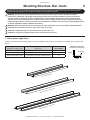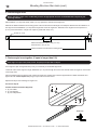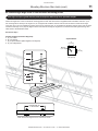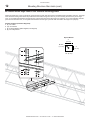
1
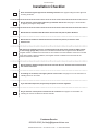
INSTALLATION GUIDE Big Ass Fan 4900 For help, call 855-490-3048 or email [email protected] BIG ASS FAN 4900 Installation Checklist Did a structural engineer approve the mounting structure? See page 6 for Big Ass Fans approved mounting structures. Do you have the correct safety cable? Are you familiar with its use? See page 17 for information on properly securing the safety cable. :LOOWKHIDQEHLQVWDOOHGVRWKDWWKHDLUIRLOVDUHDWOHDVWIWPDERYHWKHÀRRU" Will the fan be installed so that the airfoils have at least 2 ft (0.61 m) of clearance from obstructions? Will the fan be installed so that it is not subjected to high winds (such as from an HVAC system or near a large garage door)? If the fan is mounted at the same level or higher than the diffuser, the winglets must be at a distance that is at least 1x the measure of the fan’s diameter. If the fan is mounted at the same height or below the diffuser, the winglets must be at a distance that is at least 2x the measure of the fan’s diameter. Will the distance between multiple fans be at least 2.5x the fans’ diameter when measured from the centers of the fans? If installing on an I-beam, is the upper yoke the correct size? See page 15 for more information on installing the fan on an I-beam. If you ordered multiple fans, did you keep the parts of each fan together? Do you have the correct power circuit for the fan controller? See page 21 for information on selecting the correct circuit/fuse for the fan controller. Customer Service 855-490-3048 | [email protected] WWW.BIGASSFANS.COM ©2013 DELTA T CORP. ALL RIGHTS RESERVED BIG ASS FAN 4900 Installation Guide Big Ass Fan 4900 Installation Guide: Jul. 2014 Rev. F This product was manufactured in a plant whose Management 6\VWHPLVFHUWL¿HGDVEHLQJLQFRQIRUPLW\ZLWK,62 Conforms to ANSI/UL STD 507: Electric Fans &HUWL¿HGWR&$1&6$&1R)DQV9HQWLODWRUV Contact Information Manufacturing 2425 Merchant Street Lexington, KY 40511 1-877-BIG-FANS www.bigassfans.com Customer Service 2348 Innovation Drive Lexington, KY 40511 855-490-3048 [email protected] Warranty Returns 800 Winchester Road Lexington, KY 40505 1-877-BIG-FANS www.bigassfans.com All trademarks used herein are the properties of their respective owners. No part of this document may be reproduced or translated into a different language without the prior written consent of Big Ass Fan Company. The information contained in this document is subject to change without notice. WWW.BIGASSFANS.COM ©2013 DELTA T CORP. ALL RIGHTS RESERVED i BIG ASS FAN 4900 ii IMPORTANT SAFETY INSTRUCTIONS READ AND SAVE THESE INSTRUCTIONS TO REDUCE THE RISK OF FIRE, ELECTRIC SHOCK, OR INJURY TO PERSONS, OBSERVE THE FOLLOWING: :$51,1*,QVWDOODWLRQZRUNDQGHOHFWULFDOZLULQJPXVWEHGRQHE\TXDOL¿HGSHUVRQVLQDFFRUGDQFHZLWKDOODSSOLFDEOHFRGHV and standards. WARNING: When cutting or drilling into a wall or ceiling, do not damage electrical wiring and other hidden utilities. CAUTION: The installation of a Big Ass )DQPXVWEHLQDFFRUGDQFHZLWKWKHUHTXLUHPHQWVVSHFL¿HGLQWKLVLQVWDOODWLRQPDQXDO and with any additional requirements set forth by the National Electric Code (NEC), ANSI/NFPA 70-2011, and all local codes. Code compliance is ultimately YOUR responsibility! WARNING: The fan controllers contain high voltage capacitors that take time to discharge after removal of mains supply. Before working on the fan controller, ensure isolation of mains supply from line inputs at the fan controller’s disconnect. Wait three (3) minutes for capacitors to discharge to safe voltage levels. Failure to do so may result in personal injury or death. NOTE: Darkened display LEDs are not an indication of safe voltage levels. CAUTION: Exercise caution and common sense when powering the fan. Do not connect the fan to a damaged or hazardous power source. Do not attempt to resolve electrical malfunctions or failures on your own. Contact Big Ass Fans if you have any questions regarding the electrical installation of this fan. :$51,1*7RUHGXFHWKHULVNRI¿UHHOHFWULFVKRFNDQGLQMXU\WRSHUVRQV%LJAss Fans must be installed with Big Ass Fan supplied controllers that are marked (on their cartons) to indicate the suitability with this model. Other parts cannot be substituted. CAUTION: When service or replacement of a component in the fan requires the removal or disconnection of a safety device, the safety device is to be reinstalled or remounted as previously installed. :$51,1*5LVNRI¿UHHOHFWULFVKRFNRULQMXU\WRSHUVRQVGXULQJFOHDQLQJDQGXVHUPDLQWHQDQFH'LVFRQQHFWWKHDSSOLDQFH from the power supply before servicing. WARNING: Use this unit only in the manner intended by the manufacturer. If you have questions, contact the manufacturer. WARNING: Before servicing or cleaning unit, switch power off at service panel and lock the service disconnecting means to prevent power from being switched on accidentally. When the service disconnecting means cannot be locked, securely fasten a prominent warning device, such as a tag, to the service panel. CAUTION: Do not bend the airfoils when installing, adjusting, or cleaning the fan. Do not insert foreign objects between rotating airfoils. :$51,1*6WD\DOHUWDQGXVHFRPPRQVHQVHZKHQLQVWDOOLQJIDQV'RQRWLQVWDOOIDQVLIWLUHGRUXQGHUWKHLQÀXHQFHRIGUXJV alcohol, or medication. A moment of inattention while installing fans may result in serious personal injury. CAUTION: The installation of this fan requires the use of some power tools. Follow the safety procedures found in the owner’s manual for each of these tools and do not use them for purposes other than those intended by the manufacturer. CAUTION: The Big Ass Fans product warranty will not cover equipment damage or failure caused by improper installation. WARNING: This appliance is not intended for use by persons (including children) with reduced physical, sensory or mental capabilities, or lack of experience and knowledge, unless they have been given supervision or instruction concerning use of the appliance by a person responsible for their safety. Children should be supervised to ensure that they do not play with the appliance. ATTENTION: If installing the fan in the United States, the fan must be installed per the following National Fire Protection Association (NFPA) guidelines: • The fan must be centered approximately between four adjacent sprinklers. • 7KHYHUWLFDOGLVWDQFHIURPWKHIDQWRWKHVSULQNOHUGHÀHFWRUPXVWEHDWOHDVWIWFP • 7KHIDQPXVWEHLQWHUORFNHGWRVKXWGRZQLPPHGLDWHO\XSRQUHFHLYLQJDZDWHUÀRZVLJQDOIURPWKHDODUPV\VWHP Leave this installation guide with the owner of the fan after installation is complete. WWW.BIGASSFANS.COM ©2013 DELTA T CORP. ALL RIGHTS RESERVED BIG ASS FAN 4900 Contents Introduction Safety Instructions Thank You About Big Ass Fans ii 1 1 Pre-Installation About this Fan Parts Included Tools Needed Fan Diagram Preparing the Work Site 8QGHUVWDQGLQJ$LUÀRZ3DWWHUQV 2 3 4 5 6 7 Mounting Structure: Bar Joists 1. Select Proper Angle Irons 2. Pre-drill Angle Irons 3. Fasten Angle Irons Together (if span is longer than 8 ft) 4a. Fasten Single Angle Irons to Roof Structure Mounting Points 4b. Fasten Double Angle Irons to Roof Structure Mounting Points 5a. Direct Mount Main Fan Unit (to Angle Irons) 5b. Attach Upper Yoke (to Angle Irons) 9 10 10 11 12 13 14 Mounting Structure: I-Beam 1. Measure I-Beam Width 2. Attach Upper Yoke (to I-Beam) 15 16 Hanging the Fan 1. Attach Extension Tube (to Upper Yoke) 2. Secure Safety Cable 3. Attach Lower Yoke (to Extension Tube) 4. Attach Main Fan Unit (to Lower Yoke) &RQ¿UP2ULHQWDWLRQ 17 17 18 18 18 Installing Airfoils 1. Attach Winglets to Airfoils 2. Attach Airfoils to Hub 19 19 Electrical Installation Electrical Installation Safety (OHFWULFDO,QVWDOODWLRQ2YHUYLHZ Controller Storage Power Requirements for Big Ass Fans Fan Controllers Mounting the Wall Controller :LULQJ±96LQJOH3KDVH)DQ&RQWUROOHUV Wiring: ESFR (Early Suppression Fast Response) 2SHUDWLQJWKH)DQ&RQWUROOHU 20 21 21 21 21 22 23 24 Operating the Fan Heating Season Cooling Season 25 25 Preventive Maintenance Annual Preventive Maintenance General Preventive Maintenance Annual Maintenance Checklist 26 26 27 Troubleshooting General Troubleshooting Troubleshooting the Fan Controller 29 30 Warranty Warranty Policy Warranty Return Instructions Warranty Claim Form Instructions Warranty Claim Form Responsibility Agreement 33 37 38 39 40 WWW.BIGASSFANS.COM ©2013 DELTA T CORP. ALL RIGHTS RESERVED Notes BIG ASS FAN 4900 Introduction 1 Thank you and congratulations on your purchase of a Big Ass )DQDQHI¿FLHQWDQGFRVWHIIHFWLYHZD\WRVWD\FRROLQWKH summer and warm in the winter. The revolutionary design of our fans combines the best of both form and function to bring power performance and a sleek look to any setting. More importantly, you have purchased a product that is backed by extensive research, thorough testing, and quality manufacturing. We’re ready to answer any questions or comments at 855-490-3048 or email us at [email protected]. Who we are and what we do Big Ass Fans has been the preeminent manufacturer of large-diameter, low-speed fans since 1999. With a worldwide presence and located in beautiful Lexington, KY, we research, design, and manufacture the most effective air movement solutions on the market. 2XUQHYHUHQGLQJFRPPLWPHQWWRTXDOLW\DQGLQQRYDWLRQNHHSVXVDWWKHOHDGLQJHGJHRIDEXUJHRQLQJLQGXVWU\:LWKDQH\HWRKHOSLQJ customers satisfy their needs, and a strong sense of corporate responsibility to the community, Big Ass )DQVKDVUHGH¿QHGWKHZD\ business is done. WWW.BIGASSFANS.COM ©2013 DELTA T CORP. ALL RIGHTS RESERVED BIG ASS FAN 4900 2 Pre-Installation About this fan 7HFKQLFDOVSHFL¿FDWLRQV Fan size Motor size Required supply circuit size Full load current Max RPM Airfoil length Suggested distance from ceiling 14 ft (4.3 m) 1.0 HP (0.75 kW) 0$#±9ĭ 11.0 101 RPM 76” (193 cm) 5 ft (1.5 m) Motor • • • • • • • 1 hp motor NEMA Design B 9ROWV$& 1725 RPM 60 Hz, 3-phase Insulation: Class F Rating: 40° C Ambient–Continuous Reduction gear • • • • • Concentric Helical Gear Reducer Gear Hardened to 58-62 Rockwell C 3UHFLVLRQ¿QLVKHGIRUORZQRLVHDQGORQJVHUYLFHOLIH Double seals keep oil in and contaminants out Lubricated for life with synthetic oil WWW.BIGASSFANS.COM ©2013 DELTA T CORP. ALL RIGHTS RESERVED BIG ASS FAN 4900 Pre-Installation (cont.) 3 Parts included If you ordered multiple fans, be sure to keep the components of each fan together. The fans each have differently rated components that are not interchangeable. If you are missing any piece required for installation, contact Big Ass Fans Customer Service. Note: Drawings below are not to scale. No hardware substitutions are acceptable. Hardware1 Upper Yoke Hardware (4) 1/2-13 x 2” GR 8 Bolt (8) 1/2” Flat Washer (4) 1/2-13 Nylock Nut Extension Tube Hardware (2) 1/2-13 x 4-1/2” GR 8 Bolt (4) 1/2” Flat Washer (2) 1/2-13 Nylock Nut Lower Yoke Hardware (2) 1/2-13 x 4-1/2” GR 8 Bolt (4) 1/2” Flat Washer (2) 1/2-13 Nylock Nut Main Fan Unit Hardware (4) 1/2-13 x 1 3/4” GR 8 Bolt (8) 1/2” Flat Washer (4) 1/2-13 Nylock Nut Airfoil Hardware (12) 5/16-18 x 2” GR 8 Bolt (24) 5/16” Flat Washer (12) 5/16-18 Nylock Nut Winglet Hardware (6) 10-24 x 1/2” Bolt (6) 10-24 x 3/4” Barrel Mounting %HDP&OLS Spacer Main Fan Unit2 Upper Yoke (2) Lower Yoke 3-ft Extension Tube, Safety Cable36KDFNOH4 1. If your order includes yokes and an extension tube, square washers will also be included in your hardware. Square washers are needed only if you are mounting the fan to angle irons. The number of square washers needed depends on the number of angle irons that will be used. 2. The fan includes a 50-ft (15.2 m) pre-attached motor cord. 3. The safety cable is attached to the extension tube. 4. The shackle is included on the hardware boards. WWW.BIGASSFANS.COM ©2013 DELTA T CORP. ALL RIGHTS RESERVED BIG ASS FAN 4900 Pre-Installation (cont.) 4 Parts included (cont.) Note: Drawings below are not to scale. Electrical Airfoils (6) Airfoil Wall Controller1 Fire Relay2 (6) Powerfoil® Winglet (6) Airfoil Retainer 1. The wall controller includes a 10-ft (3 m) pre-attached AC supply cord with a NEMA 5-20P plug. An Electronic Programming Module (EPM) is installed in the controller. 2. 7KH¿UHUHOD\LVUHTXLUHGIRUIDQVWKDWZLOOEHLQVWDOOHGLQEXLOGLQJVWKDWKDYHD¿UHVSULQNOHUV\VWHP6HHSDJHIRU¿UHUHOD\ZLULQJGHWDLOV Tools needed Big Ass Fans recommends gathering the following tools prior to beginning installation. Mechanical installation Electrical installation Standard wrench set 3KLOOLSVDQGÀDWKHDGVFUHZGULYHU Standard socket set and ratchet 1/4” nut driver Torque wrench capable of 40 ft·lb (54.2 N·m) 5/16” nut driver 3KLOOLSVDQGÀDWKHDGVFUHZGULYHU Pair of #10 to #14AWG strippers Standard allen wrench set Pair of medium channel locks Multimeter WWW.BIGASSFANS.COM ©2013 DELTA T CORP. ALL RIGHTS RESERVED BIG ASS FAN 4900 Pre-Installation (cont.) 5 Fan diagram A. Safety Cable. A redundant safety feature that secures the fan to the mounting structure. B. Upper Yoke. Secures the fan to the mounting structure and allows the fan to adjust its center of gravity. Note: The upper yoke may differ from the illustration below. C. Extension Tube. Extends the fan from the ceiling. D. Lower Yoke. Connects the main fan unit to the extension tube. E. Motor. 6HHSDJHIRUWHFKQLFDOVSHFL¿FDWLRQV F. Hub. Secures the airfoils to the gearbox. G. Airfoil. Provides air movement. The unique, patented design provides effective air movement. H. Winglet. ,PSURYHVWKHHI¿FLHQF\RIWKHIDQ A B C D E F H G WWW.BIGASSFANS.COM ©2013 DELTA T CORP. ALL RIGHTS RESERVED BIG ASS FAN 4900 Pre-Installation (cont.) 6 Preparing the work site Before beginning installation, review the mechanical and electrical installation guidelines below. Mechanical installation • The fan weighs 150 lbs (60 kg). A suitable means for lifting the weight of the fan, such as a scissor lift, and at least two installation personnel will be required. • Big Ass )DQVFDQRQO\EHKXQJIURPDQ,EHDPRUDQJOHLURQV)RUVSHFL¿FUHTXLUHPHQWVVHHWKH0HFKDQLFDO,QVWDOODWLRQVHFWLRQ in this guide. Do not mount the fan to single purlins, trusses, or bar joists. Consult a structural engineer for installation methods not covered in this manual. I-Beam Angle Iron • The mounting structure must be able to withstand the torque forces generated by the fan. The fan generates nearly 120 ft·lb (162.7 N·m) of torque during operation. • )DQVPRXQWHGRQIDEULFDWHG,EHDPVZKLFKDUHFRPPRQLQVWHHOEXLOGLQJVFRXOGFDXVHWKHEHDPWRÀH[DQGWKHIDQWRPRYH VLJQL¿FDQWO\GXULQJRSHUDWLRQ,IWKLVÀH[LQJFDXVHVDFOHDUDQFHSUREOHP%LJAss Fans suggests contacting a structural engineer. • Adhere to the safety requirements in the table below when selecting the fan location. Safety requirement Minimum distances Clearance IWIURPDOOIDQSDUWV7KHIDQLQVWDOODWLRQDUHDPXVWEHIUHHRIREVWUXFWLRQVVXFKDVOLJKWVFDEOHV sprinklers, or other building structure. The fan should be at least 5 ft (1.5 m) from the ceiling. Blade height IWDERYHWKHIORRU +9$&HTXLSPHQW [IDQGLDPHWHULIDWVDPHOHYHORUDERYHGLIIXVHU[IDQGLDPHWHULIEHORZGLIIXVHU5HIHUWRWKH illustration below. Fan spacing 2.5x fan diameter, center-to-center Radiant/IR heaters See the manufacturer’s requirements for the minimum clearance to combustibles. If the fan is mounted at the same level or higher than the diffuser, the winglets must be at a distance that is at least 1x the measure of the fan’s diameter. +9$& Diffuser [IDQ¶VGLDPHWHU (14 ft) (4.3 m) 14-ft diameter If the fan is mounted below the diffuser, the winglets must be at a distance that is at least 2x the measure of the fan’s diameter. +9$& Diffuser [IDQ¶VGLDPHWHU (28 ft) (8.5 m) 14-ft diameter Electrical installation • 7RUHGXFHWKHULVNRIHOHFWULFVKRFNZLULQJVKRXOGEHSHUIRUPHGE\DTXDOL¿HGHOHFWULFLDQ,QFRUUHFWDVVHPEO\FDQFDXVHHOHFWULF VKRFNRUGDPDJHWKHPRWRUDQGWKHFRQWUROOHU • The installation of a Big Ass Fan must be in accordance with the National Electrical Code, ANSI/NFPA 70-2011, and all local codes. • Refer to the Electrical Installation section in this manual for detailed electrical requirements. • Controller output/motor input leads cannot share a conduit with any other controller’s AC supply feed. WWW.BIGASSFANS.COM ©2013 DELTA T CORP. ALL RIGHTS RESERVED BIG ASS FAN 4900 Pre-Installation (cont.) 7 8QGHUVWDQGLQJDLUÀRZSDWWHUQV $LUÀRZLQDQRSHQDUHD 7KHDLUÀRZPRYHVIURPWKHIDQWRZDUGWKHÀRRU 2QFHDLUÀRZKLWVWKHÀRRULWPRYHVRXWZDUGLQ DOOGLUHFWLRQV7KHGHÀHFWLRQRIDLURIIWKHÀRRULV FDOOHGD³ÀRRUMHW´ $LUÀRZLQDQHQFORVHGDUHD 7KHÀRRUMHWUDGLDWHVRXWZDUGXQWLOLWUHDFKHVWKH ZDOOVZKLFKGHÀHFWWKHMHWXSZDUG$IWHULWKLWV WKHFHLOLQJWKHXSZDUGÀRZLVGLUHFWHGLQZDUG to the low pressure area above the fan where LWLVWKHQSXOOHGGRZQWRZDUGWKHÀRRU7KLV creates a convection-like air current that gathers PRPHQWXP2QFHWKLVFXUUHQWLVHVWDEOLVKHG the fan begins to move air outside of the current, escalating its cooling effects. $LUÀRZZLWKPXOWLSOHIDQV Where there are multiple fans appropriately spaced, the expanding jets of adjacent fans meet to create a pressure zone. The pressure zone acts like a wall, causing each fan to behave like a single enclosed fan. Typically, a single fan’s performance will increase when working in conjunction with other fans. 2YHUKHDG9LHZ $LUÀRZZLWKVWUHDPOLQHGREVWUXFWLRQ 2EVWUXFWLRQVRQWKHÀRRUWHQGWREORFNWKH horizontally moving air. Thin or streamlined REVWUXFWLRQVGRQRWEORFNPXFKDLUÀRZ UHJDUGOHVVRIVL]H7KHDLUWHQGVWRÀRZ smoothly around these obstructions, losing little momentum, and leaving only a small stagnant area behind the obstruction. 6LGH9LHZ $LUÀRZZLWKZLGHEOXQWREVWUXFWLRQ $ZLGHEOXQWRUÀDWIDFHGREVWUXFWLRQIRUFHV the air to change direction, turning upward and outward. There is a stagnant area behind these obstructions that is wider and higher than the obstructions themselves. WWW.BIGASSFANS.COM ©2013 DELTA T CORP. ALL RIGHTS RESERVED BIG ASS FAN 4900 8 Pre-Installation (cont.) $LUÀRZWLSV Below are some techniques that make a dramatic difference in congested areas of your facility. Treat air like water, and scoop, direct, and channel it to where it is needed most. • 0DNHVXUHSHRSOHDUHQRWKLGGHQEHKLQGVWUXFWXUHVWKDWZRXOGEORFNDLUÀRZ7KLVPD\VHHPREYLRXVEXWZRUNDUHDVDUHURXWLQHO\ blocked by shelving, crates, and machinery. • 3RVLWLRQODUJHREVWUXFWLRQVVRWKDWWKHLUVPDOOHVWSUR¿OHVDUHSHUSHQGLFXODUWRWKHGLUHFWLRQRIDLUPRYHPHQW)RUH[DPSOHDVKHHW PHWDOSUHVVEUDNHPLJKWKDYH¿YHWLPHVWKHIURQWDODUHDLILWLVIDFLQJWKHDLUÀRZUDWKHUWKDQLILWLVWXUQHGVLGHZD\V • :KHUHYHUSRVVLEOHSRVLWLRQZHOGLQJFXUWDLQVSDUWLWLRQVVKHHWPDWHULDOVHWFWRVFRRSDLULQWRWKHZRUNDUHDUDWKHUWKDQGHÀHFWLW • 7DNHDGYDQWDJHRIWKHDLUPRYLQJQHDUWKHÀRRUE\FUHDWLQJJURXQGOHYHORSHQLQJVLQ\RXUZRUNDUHD,WLVEHWWHUWRKDYHDZRUNDUHD blocked by materials stacked to the ceiling with an opening below than to have low stacks 3 ft (0.9 m) to 6 ft (1.8 m) high sitting on WKHÀRRU WWW.BIGASSFANS.COM ©2013 DELTA T CORP. ALL RIGHTS RESERVED BIG ASS FAN 4900 9 Mounting Structure: Bar Joists Big Ass Fans can only be hung from an I-beam or bar joists. See page 15 for I-beam mounting instructions (optional). Consult a structural engineer for installation methods not covered in this manual. WARNING: The fan should not be installed unless the structure on which the fan is to be mounted is of sound construction, undamaged, and capable of supporting the loads of the fan and its method of mounting. A structural engineer should verify that the structure is adequate prior to fan installation. Verifying the stability of the mounting structure is the sole responsibility of the customer and/or end user, and Big Ass Fans hereby expressly disclaims any liability arising therefrom, or arising from the use of any materials or hardware other than those supplied by Big Ass Fans RURWKHUZLVHVSHFL¿HGLQWKHVHLQVWDOODWLRQLQVWUXFWLRQV WARNING: Never use beam clips when mounting fans to angle irons! Beam clips are intended for I-beam installations. CAUTION: Do not install the fan from a single purlin, truss, or bar joist. CAUTION: Unsupported angle iron spans should not exceed 12 ft (3.7 m). CAUTION: The angle irons must be fastened to the roof structure at each end. 1. Select proper angle irons Follow the table below when selecting angle irons for fan installation. Note: Angle irons and angle iron hardware are not included with the fan. Angle iron span (between mounting points) Minimum angle iron dimensions (W x H x T) Number of angle irons needed 6 ft (1.8 m) or less 2.5” (6.4 cm) x 2.5” (6.4 cm) x 0.25” (0.6 cm) 2 6 ft (1.8 m) to 8 ft (2.4 m) 3” (7.6 cm) x 3” (7.6 cm) x 0.25” (0.6 cm) 2 8 ft (2.4 m) to 12 ft (3.7 m) 3” (7.6 cm) x 3” (7.6 cm) x 0.25” (0.6 cm) 4* *Two pairs of angle irons. Pairs should be placed back to back and fastened in center (see step 3). ess ) or l 8m 6’ (1. over over WWW.BIGASSFANS.COM ’ (2.4 –8 .8m) 6’ (1 4 8’ (2. m) ’ (3.7 12 m) – ©2013 DELTA T CORP. m) ALL RIGHTS RESERVED Angle Iron Side View (see table for dimensions) Height Thickness Width BIG ASS FAN 4900 Mounting Structure: Bar Joists (cont.) 10 2. Pre-drill angle irons %HIRUHGULOOLQJWKHDQJOHLURQVFRQ¿UPWKDW\RXKDYHWKHDSSURSULDWHPRXQWWRDFFRPPRGDWHWKHURRISLWFKRI\RXU mounting structure. Drill two Ø9/16” (1.4 cm) holes exactly 5-3/8” (13.7 cm) apart in the centers of two angle irons. Measure the distance between the mounting points of the roof structure that the angle irons will span. Measure the same distance on the angle irons and drill Ø9/16” (1.4 cm) holes through each end of the angle irons. Drill holes in two angle irons if the span is 8 ft (2.4 m) or less. Drill holes in 4 angle irons if span is greater than 8 ft (2.4 m). A Ø 9/16’’ (1.4 cm) 1/2 A Mount with extension tube: 5-3/l8’’ (13.7 cm) Direct mount: 5-1/2’’ (14 cm) Distance between roof structure mounting points 3. Fasten angle irons together (if span is longer than 8 ft) If the angle iron span is 8 ft (2.4 m) or less, skip step 3 and proceed to step 4a. If the angle iron span is longer than 8 ft (2.4 m), it is necessary to use double angle irons. Locate the center of the angle iron length. Drill Ø9/16” (1.4 cm) hole through the center of the vertical wall of the angle iron. Drill a total of four angle irons. Place two drilled angle irons back to back. Fasten the angle irons together with customer-supplied Ø1/2-13 Grade 8 hardware and tighten the bolts to 40 ft·lb (54.2 N·m) using a torque wrench and 3/4” socket. Repeat this step for the remaining two angle irons. Proceed to step 4b. c Grade 8 Hardware (Customer-Supplied): a. (2) 1/2-13 Bolt b. (4) 1/2” Washers c. (2) 1/2-13 Nylock Nut b b a Side view WWW.BIGASSFANS.COM ©2013 DELTA T CORP. ALL RIGHTS RESERVED BIG ASS FAN 4900 Mounting Structure: Bar Joists (cont.) 11 4a. Fasten single angle irons to roof structure mounting points If the angle iron span is greater than 8 ft (2.4 m) and requires double angle irons, proceed to step 4b. Fasten the angle irons to the roof structure mounting points at each end with customer-supplied Grade 8 hardware as shown. If you are mounting the fan directly to the angle irons, do not tighten the hardware until the main fan unit has been mounted to the angle irons (step 5a). If your fan installation includes yokes and an extension tube, do not tighten the hardware until the upper yoke has been mounted to the angle irons (step 5b). Big Ass Fans recommends orienting the angle irons so that the horizontal legs are facing each other. Refer to the illustration below. Proceed to step 5. Grade 8 Hardware (Customer-Supplied): a. (4) 1/2-13 Bolt b. (8) 1/2” Washer c. (4) 3” Square Washer (BAF-Supplied; see diagram) d. (4) 1/2-13 Nylock Nut Square Washer 3” (7.6 cm) Ø 9/16” (1.4 cm) a 3” (7.6 cm) Thickness: 1/4” (6 mm) b c b d 9HUWLFDOZDOOVDUH to the outside. Note: Ensure the angle irons are oriented as shown. WWW.BIGASSFANS.COM ©2013 DELTA T CORP. ALL RIGHTS RESERVED BIG ASS FAN 4900 Mounting Structure: Bar Joists (cont.) 12 4b. Fasten double angle irons to roof structure mounting points Fasten the angle irons to the roof structure mounting points at each end with customer-supplied Grade 8 hardware as shown. The angle irons with fan mounting holes should be positioned on the inside, facing each other. If you are mounting the fan directly to the angle irons, do not tighten the hardware until the main fan unit has been mounted to the angle irons (step 5a). If your fan installation includes yokes and an extension tube, do not tighten the hardware until the upper yoke has been mounted to the angle irons (step 5b). Grade 8 Hardware (Customer-Supplied): a. (8) 1/2-13 Bolt b. (16) 1/2” Washer c. (8) 3” Square Washer (BAF-Supplied; see diagram) d. (8) 1/2-13 Nylock Nut Square Washer 3” (7.6 cm) Ø 9/16” (1.4 cm) 3” (7.6 cm) a Thickness: 1/4” (6 mm) b c b d WWW.BIGASSFANS.COM ©2013 DELTA T CORP. ALL RIGHTS RESERVED BIG ASS FAN 4900 Mounting Structure: Bar Joists (cont.) 13 5a. Direct mount main fan unit (to angle irons) If your fan installation includes yokes and an extension tube, skip this step and proceed to step 5b. CAUTION: The main fan unit is heavy. Use caution when raising it. Attach the main fan unit directly to the angle irons with the Main Fan Unit Hardware as shown. Consult the diagram below for distances between the angle irons. Note: The fan can only be directly mounted to angle irons. Do not directly mount the fan to an I-beam. Tighten the bolts to 40 ft·lb (54.2 N·m) using a torque wrench and 3/4” socket. After attaching the main fan unit to the angle irons, tighten all the bolts securing the angle irons to the roof structure to 40 ft·lb (54.2 N·m) using a torque wrench and 3/4” socket. Proceed to “Secure Safety Cable” (p. 17). Main Fan Unit Hardware (BAF-Supplied): a. (4) 1/2-13 x 1 3/4” GR 8 Bolt b. (8) 1/2’’ Flat Washer c. (4) 1/2-13 Nylock Nut 5 1/2” (14 cm) a b b c WWW.BIGASSFANS.COM ©2013 DELTA T CORP. ALL RIGHTS RESERVED BIG ASS FAN 4900 14 Mounting Structure: Bar Joists (cont.) 5b. Attach upper yoke (to angle irons) Secure the upper yoke directly to the angle irons with the Upper Yoke Hardware as shown. The angle irons should be aligned with the outermost holes of the upper yoke. Consult the diagrams below for distances between the angle irons. Tighten the bolts to 40 ft·lb (54.2 N·m) using a torque wrench and 3/4” socket. After attaching the upper yoke to the angle irons, tighten all the bolts securing the angle irons to the roof structure to 40 ft·lb (54.2 N·m). Proceed to “Hanging the Fan” (p. 17). Upper Yoke Hardware (BAF-Supplied): a. (4) 1/2”-13 x 2” GR 8 Bolt b. (8) 1/2’’ Flat Washer c. (4) 1/2-13 Nylock Nut 10-7/8” (27.6 cm) Upper Yoke 13-3/4’’ (34.9 cm) x 9-5/8” (24.4 cm) Note: Dashed lines represent angle irons. The angle irons should be aligned with the outermost holes on the upper yoke. Do not use beam clips on angle irons! Side View a b b c WWW.BIGASSFANS.COM ©2013 DELTA T CORP. ALL RIGHTS RESERVED BIG ASS FAN 4900 Mounting Structure: I-Beam 15 Big Ass Fans can only be hung from an I-beam or bar joists. See page 9 for bar joist mounting instructions. Consult a structural engineer for installation methods not covered in this manual. WARNING: The fan should not be installed unless the structure on which the fan is to be mounted is of sound construction, undamaged, and capable of supporting the loads of the fan and its method of mounting. A structural engineer should verify that the structure is adequate prior to fan installation. Verifying the stability of the mounting structure is the sole responsibility of the customer and/or end user, and Big Ass Fans hereby expressly disclaims any liability arising therefrom, or arising from the use of any materials or hardware other than those supplied by Big Ass Fans RURWKHUZLVHVSHFL¿HGLQWKHVHLQVWDOODWLRQLQVWUXFWLRQV CAUTION: It is not recommended to mount a Big Ass Fan to a fabricated I-beam. Do not direct mount the fan to an I-beam. CAUTION: The I-beam on which the fan will mount must be part of the existing building structure. &$87,21,QVWDOOWKHVSDFHUVRQO\LIWKHWKLFNQHVVRIWKH,EHDPÀDQJHH[FHHGV´FP7KHPRXQWLQJKROHVRQWKH spacer are closer to one edge than the other. Make sure this edge of the spacer is facing the I-beam. WARNING: Ensure there are no persons below the fan unit during installation! 1. Measure I-beam width 0HDVXUHWKHÀDQJHZLGWKRIWKH,EHDPIURPZKLFKWKHIDQZLOOEHKXQJ6HOHFWWKHXSSHU\RNHPRXQWLQJKROHVWKDWPDWFKWKHÀDQJH width of the I-beam. outer holes middle holes inner holes Upper Yoke 13-3/4’’ (349 mm) x 10” (258 mm) I-beam ÀDQJHZLGWK Upper yoke mounting holes 5” (127 mm) to 6-5/8” (168 mm) Inner holes >6-5/8” (168 mm) to 8-1/4” (210 mm) Middle holes >8-1/4”(210 mm) to 9-7/8”(250 mm) 2XWHUKROHV WWW.BIGASSFANS.COM Upper Yoke (top view) ©2013 DELTA T CORP. ALL RIGHTS RESERVED BIG ASS FAN 4900 Mounting Structure: I-Beam (cont.) 16 2. Attach upper yoke (to I-beam) Secure the upper yoke to the I-beam with the Upper Yoke Hardware as shown. Tighten the bolts to 40 ft·lb (54.2 N·m) using a torque wrench and 3/4” socket. Upper Yoke Hardware (BAF-Supplied): a. (4) 1/2-13 x 2” GR 8 Bolt b. (8) 1/2’’ Flat Washer c. (4) 1/2-13 Nylock Nut d. (2) Beam Clip e. (2) Spacer Proceed to “Hanging the Fan” (p. 17). Side View a b d e b c 6SDFHUVDUHRQO\XVHGLIWKHEHDPÀDQJH exceeds 3/8” (1 cm). Note: Ensure the spacers are oriented as shown. WWW.BIGASSFANS.COM ©2013 DELTA T CORP. ALL RIGHTS RESERVED BIG ASS FAN 4900 Hanging the Fan 17 1. Attach extension tube (to upper yoke) If the fan will be directly mounted to angle irons, skip this step and proceed to step 2 below. Fasten the extension tube to the upper yoke with the Extension Tube Hardware as shown. Ensure the extension tube is hanging plumb to the ground, and then tighten the hardware so that it is snug, but not fully tightened. c Extension Tube Hardware (BAF-Supplied): a. (2) 1/2-13 x 4-1/2’’ GR 8 Bolt b. (4) 1/2’’ Flat Washer c. (2) 1/2-13 Nylock Nut b b a 2. Secure safety cable The safety cable is a crucial part of the fan and must be installed correctly. If you have questions, call Customer Service for assistance. Angle iron mount (no extension tube) Route the cable through the motor frame and around the angle irons as shown. Connect the looped ends of the cable with the shackle. The cable must be drawn tightly around the angle irons, leaving as little slack as possible. The shackle should be on the topside of the angle iron if possible. Securely tighten the shackle. Angle iron mount (with extension tube) Secure the safety cable by wrapping it around the angle irons and connecting the looped ends with the shackle as shown. The cable must be drawn tightly around the angle irons, leaving as little slack as possible. The shackle should be on the topside of the angle irons if possible. Securely tighten the shackle. Proceed to Installing Airfoils on p. 19. Proceed to step 3. I-Beam mount Secure the safety cable by wrapping it around the I-beam and connecting the looped ends with the shackle as shown. The cable must be drawn tightly around the I-beam, leaving as little slack as possible. If possible, the shackle should be on the topside of the I-beam. Securely tighten the shackle. Proceed to step 3. Shackle WWW.BIGASSFANS.COM ©2013 DELTA T CORP. ALL RIGHTS RESERVED BIG ASS FAN 4900 Hanging the Fan (cont.) 18 3. Attach lower yoke (to extension tube) Attach the lower yoke to the bottom of the extension tube with the Lower Yoke Hardware as shown. Tighten the hardware so that it is snug, but not fully tightened. Lower Yoke Hardware (BAF-Supplied): a. (2) 1/2-13 x 4-1/2’’ GR 8 Bolt b. (4) 1/2’’ Flat Washer c. (2) 1/2-13 Nylock Nut c b b a 4. Attach main fan unit (to lower yoke) CAUTION: The main fan unit is heavy. Use caution when raising it. Attach the main fan unit to the lower yoke with the Main Fan Unit Hardware as shown. Do not rest the main fan unit on the ground! Make sure the lower cable is positioned between the lower yoke brackets as shown on the right. a Tighten the bolts to 40 ft·lb (54.2 N·m) using a torque wrench and 3/4” socket. Do not discard the main fan unit packaging. It should be used if the fan is ever moved or relocated. b Main Fan Unit Hardware (BAF-Supplied): a. (4) 1/2-13 x 1-3/4” GR 8 Bolt b. (8) 1/2’’ Flat Washer c. (4) 1/2-13 Nylock Nut b c &RQ¿UPRULHQWDWLRQ After securing the main fan unit to the lower yoke, allow the fan to hang so that the extension tube is plumb to the ground. When it is properly positioned, fully tighten the mounting hardware (Lower Yoke Hardware and Extension Tube Hardware) to 40 ft·lb (54.2 N·m). WWW.BIGASSFANS.COM ©2013 DELTA T CORP. ALL RIGHTS RESERVED BIG ASS FAN 4900 19 Installing Airfoils Big Ass Fans recommends completing electrical installation (p. 20) before installing the airfoils. WARNING: Disconnect power to the fan before installing the airfoils. 1. Attach winglets to airfoils Attach the winglets to the airfoils using the Winglet Hardware as shown. %RWKD3KLOOLSVKHDGDQGÀDWKHDGVFUHZGULYHUDUHUHTXLUHGWRSURSHUO\ secure the fasteners. Attach winglets to all six airfoils before attaching the airfoils to the fan. a Winglet Hardware (BAF-Supplied): a. (6) 10-24 x 3/4” Barrel b. (6) 10-24 x 1/2” Bolt b 2. Attach airfoils to hub Slide the airfoils onto the tabs of the fan hub. The airfoils must be attached to the fan hub with the curved sides facing downward. Attach the six airfoil retainers with the Airfoil Hardware. Moving clockwise around the fan hub, position the airfoil retainers end over end as shown. Hole A of the retainer should be positioned over top of Hole B. Do not tighten the bolts until all the airfoil retainers have been attached! a Tighten the bolts along the outer perimeter to 29 ft·lb (39.3 N·m) using a torque wrench and 1/2” socket. After the outer perimeter bolts are torqued, tighten the bolts along the inner perimeter to 29 ft·lb (39.3 N·m) using a torque wrench and 1/2” socket. b Airfoil Hardware (BAF-Supplied): a. (12) 5/16-18 x 2’’ GR 8 Bolt b. (24) 5/16” Flat Washer c. (12) 5/16-18 Nylock Nut Airfoil Retainer b Hole A c Hole B WWW.BIGASSFANS.COM ©2013 DELTA T CORP. ALL RIGHTS RESERVED BIG ASS FAN 4900 20 Electrical Installation :$51,1*7RUHGXFHWKHULVNRIHOHFWULFVKRFNZLULQJVKRXOGEHSHUIRUPHGE\DTXDOL¿HGHOHFWULFLDQ,QFRUUHFWDVVHPEO\FDQ cause electric shock or damage the motor and the controller! Hazard of electrical shock! WARNING: The installation of a Big Ass )DQPXVWEHLQDFFRUGDQFHZLWKWKHUHTXLUHPHQWVVSHFL¿HGLQWKLVLQVWDOODWLRQPDQXDO and with any additional requirements set forth by the National Electric Code (NEC), ANSI/NFPA 70-2011, and all local codes. Code compliance is ultimately YOUR responsibility! WARNING: The fan controllers contain high voltage capacitors that take time to discharge after removal of mains supply. Before working on the fan controller, ensure isolation of mains supply from line inputs at the fan controller’s disconnect if installed. Wait three (3) minutes for capacitors to discharge to safe voltage levels. Failure to do so may result in personal injury or death. Note: Darkened display LEDs are not an indication of safe voltage levels. CAUTION: It is the sole responsibility of the installer to verify the operating voltage of the fan system prior to installation! It is also mandatory that the installer verify that airfoils, motor hub assemblies, and fan controllers are matched properly at the time of installation, especially if multiple fan systems will be installed. CAUTION: An incorrectly installed controller can result in component damage or reduction in the fan’s life. Wiring or application errors such as under-sizing the controller, incorrect or inadequate AC supply, or excessive ambient temperatures may result in a malfunction of the fan system. Verify correct voltage, phase, and horsepower before beginning installation! WARNING: Exercise caution and common sense when powering the fan. Do not connect the fan to a damaged or hazardous power source. Do not attempt to resolve electrical malfunctions or failures on your own. Contact Big Ass Fans if you have any questions regarding the electrical installation of this fan. CAUTION: For use with Big Ass Fans-supplied variable frequency drive only. Not for use with other speed control devices! CAUTION: The product warranty will not cover equipment damage or failure that is caused by improper installation. CAUTION: The following information is merely a guide for proper installation. Big Ass Fans cannot assume responsibility for the compliance or the non-compliance to any code, national, local, or otherwise for the proper installation of these fan controllers, fans, or associated equipment. A hazard of personal injury and/or equipment damage exists if codes are ignored during installation. WWW.BIGASSFANS.COM ©2013 DELTA T CORP. ALL RIGHTS RESERVED BIG ASS FAN 4900 Electrical Installation (cont.) 21 Electrical installation overview The electrical installation section is intended for a professional electrician. If you are unfamiliar or uncomfortable with installing electrical components, do not attempt to install the fan without an electrician. Serious personal injury or damage to the fan and other equipment could result. This guide is merely a recommendation of proper installation. Adhering to national and local electric codes is your UHVSRQVLELOLW\,WLVWKHVROHUHVSRQVLELOLW\RIWKHLQVWDOOHUWRYHULI\WKHRSHUDWLQJYROWDJHRIWKHIDQV\VWHPSULRUWRLQVWDOODWLRQ,WLVDOVR mandatory that the installer verify that airfoils, motor assemblies, and fan controllers are matched properly at the time of installation, especially if multiple fan systems will be installed. The following sections outline how to prepare for the electrical installation, how to properly wire the fan controller, and proper startup procedures. Controller storage Store the controller within an ambient temperature range of -40°F to 185°F (-40°C to 85°C) and a relative humidity range of 0 to 95%, non-condensing. Do not expose the controller to a corrosive atmosphere. If the controller has been in storage or disconnected from power for more than one year, apply AC supply power to the controller for a period of two hours prior to operation in order to recondition the internal DC bus capacitors. Power requirements for fan controllers The power requirements for fan controllers are listed in the table on page 2. If multiple controls are connected to one feeder circuit, the circuit required is the sum of the feeder circuit requirements listed on the chart. This type of installation will also require that each fan control be installed downstream from a dedicated over-current protection device. Mounting the wall controller Mount the controller to a wall using a #8–#10 screw. Adhere to the following guidelines when selecting the controller location: • ,QVWDOOWKHFRQWUROOHURQDÀDWVXUIDFHWKDWLVUHDGLO\DFFHVVLEOHIUHHIURPYLEUDWLRQDQGZKHUHWKHUHLVDGHTXDWHGLVWDQFHIURPIRUHLJQ objects or moving equipment. • Do not mount any controller adjacent to or above a heat source or heat-producing equipment. • The ambient temperature must be between 14º F (-10º C) and 122º F (50º C). • Do not expose the controller to a corrosive atmosphere, moisture, or direct sunlight. • When mounting the controller, keep in mind that the fan should be visible from the controller. • A minimum distance of 6” (15.2 cm) should be maintained between fan controllers. 6.28” (160 mm) 5.90” (150 mm) FWD RUN 6.56”(167 mm) 8.00” (203 mm) REV M R F STOP 4.47”(114 mm) AUTO 1 2 5 6 25 4 11 13A13B13C 14 30 16 17 U/T1 V/T2 W /T3 PE L1 L2 N WWW.BIGASSFANS.COM ©2013 DELTA T CORP. ALL RIGHTS RESERVED BIG ASS FAN 4900 22 Electrical Installation (cont.) Wiring: 100–125V single-phase fan controllers WARNING: Wait three minutes after disconnecting before servicing! :$51,1*,PSURSHULQVWDOODWLRQFDQFDXVHHOHFWULFVKRFNRUGDPDJHWRWKHPRWRUDQGFRQWUROOHU$TXDOL¿HGHOHFWULFLDQ should perform the installation. 7KHGLDJUDPEHORZVKRZVZLULQJIRUD±9ĭ+]IDQFRQWUROOHU6HHSDJHIRUGHWDLOHGSRZHUUHTXLUHPHQWV The fan includes a 50-ft (15.2 m) pre-attached motor cord and a 10-ft (3 m) pre-attached controller AC supply cord with a NEMA 5-20P plug. Motor Cord 1 2 5 6 25 4 11 13A13B13C 14 30 16 17 L1 L2 WHITE E V/T2 W/T3 PE BLACK WHIT RED BLACK U/T1 N G REEN W/ Controller with attached AC supply cord and NEMA 5-20P plug GR BLACK WHITE Y EL LO W LLOW / YE NW EE The L2 terminal is not used when wiring the fan FRQWUROOHUIRU±9ĭ7KLVIDQFRQWUROOHUGRHV not include a disconnect. Note: This fan controller does not contain fusing! Power must be supplied to this controller via a dedicated circuit breaker or properly fused disconnect! WWW.BIGASSFANS.COM AC Input Wiring 2W plus GND ©2013 DELTA T CORP. ALL RIGHTS RESERVED Motor Output Wiring 3W plus GND BIG ASS FAN 4900 Electrical Installation (cont.) 23 Wiring: ESFR (Early Suppression Fast Response) WARNING: Wait three minutes after disconnecting before servicing! :$51,1*,PSURSHULQVWDOODWLRQFDQFDXVHHOHFWULFVKRFNRUGDPDJHWRWKHPRWRUDQGFRQWUROOHU$TXDOL¿HGHOHFWULFLDQ should perform the installation. ATTENTION: If installing the fan in the United States, the fan must be installed per the following National Fire Protection Association (NFPA) guidelines: • The fan must be centered approximately between four adjacent sprinklers. • 7KHYHUWLFDOGLVWDQFHIURPWKHIDQWRWKHVSULQNOHUGHÀHFWRUPXVWEHDWOHDVWIWFP • 7KHIDQPXVWEHLQWHUORFNHGWRVKXWGRZQLPPHGLDWHO\XSRQUHFHLYLQJDZDWHUÀRZVLJQDOIURPWKHDODUPV\VWHP 7KH¿UHUHOD\LQFOXGHGZLWKWKHIDQLVQHHGHGRQO\LIWKHIDQZLOOEHLQVWDOOHGLQDEXLOGLQJWKDWKDVD¿UHVSULQNOHUV\VWHP7KH¿UHUHOD\ integrates the fan with the sprinkler system and shuts down the fan upon receiving an alarm signal from the system. If the building in which the fan will be installed has a sprinkler system, you must install the relay according to the instructions below. $FRQWDFWFORVXUHDFURVVWKHGLJLWDOLQSXWWHUPLQDOVDQG$ZLOOUHVXOWLQIDQVKXWGRZQ7KHLQFOXGHGUHOD\XVHVD1RUPDOO\2SHQ 12FRQWDFWDVVKRZQEHORZ7KHUHOD\FRLOPXVWEHHQHUJL]HGE\WKH)$&3IRUIDQVKXWGRZQ2SWLRQDOO\WKHQRUPDOO\FORVHG1& relay contact can be used. The relay coil must remain energized by the FACP for fan operation. This would be considered a fail safe or fail open wiring arrangement. Two additional relay coil leads are provided to facilitate supervision pass-through where required. 7HUPLQDOV$ for ESFR Relay AUTO FWD 1 2 5 6 25 4 11 13A13B13C 14 30 16 17 M U/T1 V/T2 W/T3 PE L1 L2 F STOP An alarm condition will stop the fan and issue an “F_EF” external fault on the fan controller’s display. ORANGE BLUE R N From Main FACP or NAC Box if Applicable YELLOW RED PAM‐SD WHITE RUN REV Relay Coil/Contact Details White (X2) (-) C Blue NC Yellow Red (X2) Relay is mounted to the backside of the access cover. WWW.BIGASSFANS.COM (+) 12 2UDQJH &RLO±9'&#P$ ©2013 DELTA T CORP. ALL RIGHTS RESERVED BIG ASS FAN 4900 Electrical Installation (cont.) 24 Operating the fan controller WARNING: The following startup procedures apply to standard model controllers. Procedures may vary depending on installation options and system automation. The installer should verify proper wiring, terminations, and proper voltage VXSSO\EHIRUHSURFHHGLQJ+LJKYROWDJHJORYHVDQGDUFÀDVKSURWHFWLRQDUHUHFRPPHQGHG Starting and stopping the fan 7KH581DQG6723EXWWRQVFRQWUROWKHIDQVWDUWDQGVWRS functions. To start the fan, press the green RUN button. To stop the fan,SUHVVWKHUHG6723EXWWRQ RUN AUTO FWD M STOP RUN REV Adjusting fan speed R F The Arrow buttons control speed adjustment. To adjust fan speed, press the Up or Down Arrow button. Single presses will increase or decrease the speed in 1-2% increments. Pressing and holding the Up or Down Arrow button will slowly and continuously adjust fan speed until the button is released. STOP Drive Idle/Stopped Screen Reversing direction of fan rotation AUTO FWD R RUN REV M R F then The direction of fan rotation can be reversed when the fan is stopped or running. To reverse the direction of rotation, press the Direction button, and then press the Memory/Enter button (as VKRZQRQWKHOHIW7KHDVVRFLDWHG'LUHFWLRQLQGLFDWRUZLOOÀDVK indicating the pending change. M F STOP Fan Speed Percentage Display (73.5% Running FWD) AUTO FWD RUN REV M R F STOP Typical Fault Message Display ,QFRPLQJ/LQH2YHU9ROWDJH6KRZQ WWW.BIGASSFANS.COM ©2013 DELTA T CORP. ALL RIGHTS RESERVED BIG ASS FAN 4900 Operating the Fan 25 Big Ass )DQVDUHWKHKLJKHVWTXDOLW\PRVWPHWLFXORXVO\HQJLQHHUHG+9/6IDQVRQWKHSODQHWPRYLQJDORWRIDLUZLWKWKHLUVL]HQRW speed. Moving at a low speed means less energy used for operation, translating into more energy savings year-round. Follow the SURFHGXUHVEHORZWRHQVXUHWKHPRVWHI¿FLHQWRSHUDWLRQRI\RXU%LJAss Fan. To ensure proper fan rotation: 1. Turn on the fan. 2. 9HULI\WKDWWKHIDQLVURWDWLQJLQWKHFRXQWHUFORFNZLVHGLUHFWLRQZKHQYLHZHGIURPEHORZ 3. If the fan is not rotating counterclockwise, reverse the direction of rotation. See the previous page for instructions on changing the direction of rotation. Heating season Big Ass )DQIDQVUHWXUQKHDWIURPWKHFHLOLQJWRÀRRUOHYHOPRUHHI¿FLHQWO\WKDQVPDOOFHLOLQJIDQV)RUPD[LPXPHQHUJ\VDYLQJV the fan should be operated continuously during the heating season and should not be operated in reverse (clockwise). Big Ass Fans are GHVLJQHGWRRSHUDWHHI¿FLHQWO\DWYHU\ORZVSHHGVVRWXUQLQJWKHIDQYHU\VORZO\LQWKHIRUZDUGGLUHFWLRQFRXQWHUFORFNZLVHZLOOSURYLGH HQRXJKDLUPRYHPHQWWRFLUFXODWHWKHKRWDLUDWWKHFHLOLQJGRZQWRWKHÀRRUZLWKRXWFDXVLQJGUDIWV Adjust the fan speed to the appropriate starting fan speed listed in the table below. Floor-to-ceiling height (ft) Starting fan speed Display % <40 15 Hz 20–30% 20 Hz 30–40% Stand directly below the tips of the airfoils with hand outstretched. If you feel a draft, slightly decrease the fan speed (0.5). Repeat until the draft is no longer noticeable. Cooling season The cooling effect created by the breeze from Big Ass Fan 4900 fans keeps occupants comfortable with the thermostat at a higher setting. During the cooling season, every degree higher that the thermostat is reset reduces the energy consumed by the air conditioner by 1.5–2%. To minimize energy usage during the cooling season, operate the fan only when building occupants are present. Adjust the fan speed to the appropriate starting fan speed listed in the table below. Floor-to-ceiling height (ft) Starting fan speed Display % <40 25 Hz 40–50% 40 Hz 60–70% Increase the speed of the fan until desired air speed or maximum fan speed is reached. In air conditioned facilities, increase the thermostat setting by 2 to 7°F to save energy. WWW.BIGASSFANS.COM ©2013 DELTA T CORP. ALL RIGHTS RESERVED BIG ASS FAN 4900 26 Preventive Maintenance WARNING: Before servicing or cleaning unit, switch power off at service panel and lock the service disconnecting means to prevent power from being switched on accidentally. When the service disconnecting means cannot be locked, securely fasten a prominent warning device to the service panel, such as a tag. WARNING: When service or replacement of a component in the fan requires the removal or disconnection of a safety device, the safety device is to be reinstalled or remounted as previously installed. Please take a few moments each year to perform the following preventive maintenance inspection on your fan to ensure its safe and HI¿FLHQWRSHUDWLRQ%HIRUHFRQWDFWLQJ&XVWRPHU6HUYLFHWU\PHQGLQJWKHLVVXHXVLQJWKHWURXEOHVKRRWLQJSURFHGXUHVRQSDJH,I\RX have any questions, contact Customer Service. Note: Actual installation setup may differ from picture. Annual preventive maintenance Perform the following maintenance procedures each year using the Annual Maintenance Checklist on the following page. 1. Check for the presence of the safety cable and shackle. The cable should be wrapped around the angle irons/I-beam leaving as little slack as possible. The shackle should be securely tightened and located on the topside of the angle irons/I-beam. 2. Ensure all mounting bolts are present and torqued to 40 ft·lb (54.2 N·m). There are four (4) bolts for direct mount installations and 12 bolts for installations with an extension tube. 3. Inspect motor terminations inside the junction box and tighten if necessary. 4. Check the gear reducer for oil leakage. If leakage is present, contact Customer Service. 5. Ensure all 12 bolts securing the airfoils to the fan are present and torqued to 29 ft·lb (39.3 N·m). 6. Ensure the airfoils are secured to one another by airfoil retainers. 7. Ensure the bolts securing the winglets to the airfoils are securely tightened. 8. ,QVSHFWIRUVLJQVRIFRUURVLRQGLVFRORUDWLRQSLWWLQJRUÀDNLQJRIPHWDO 9. Inspect the airfoils and hub for signs of damage or cracks. General preventive maintenance • Check all connections in the fan controller and tighten as needed. Using a vacuum, remove all dust and debris from the inside and outside of the controller. • 9HULI\SURSHUIDQURWDWLRQ7KHIDQVKRXOGEHWXUQLQJFRXQWHUFORFNZLVHZKHQYLHZHGIURPWKH ÀRRU • Dust the airfoils, motor, and motor housing. If desired, use a gentle cleaner or degreasing agent to polish the foils. Do not use Clorox®RURWKHUFKORULQHEDVHGFOHDQHUV7KLVFRXOG result in the release of toxic/fatal fumes. • 2EVHUYHWKHPRWLRQRIWKHIDQGXULQJRSHUDWLRQ7KHIDQVKRXOGQRWZREEOHRU precess. If any wobble is noticed, ensure the mounting structure is rigid enough to support the fan. WARNING: Do not operate a fan with missing or damaged components. Please contact Customer Service. WWW.BIGASSFANS.COM ©2013 DELTA T CORP. ALL RIGHTS RESERVED Annual Maintenance Checklist Fan Model: Fan Model: Fan Model: Serial #: Serial #: Serial #: Location: Location: Location: Date Initials Date Initials Date Initials BIG ASS FAN 4900 Troubleshooting 29 General troubleshooting For questions about your product or customer service inquiries, please call our toll free number (855-490-3048). Some issues can be resolved before requesting service. Review the below troubleshooting tips before contacting Customer Service for support. Symptom Possible solution(s) The fan is turning in the wrong direction. To be effective, the fan should be rotating in the counterclockwise direction when viewed IURPWKHÀRRU,IWKHIDQLVQRWURWDWLQJLQWKHFRXQWHUFORFNZLVHGLUHFWLRQSUHVVWKH)5 button on the controller. A popping noise is coming from the fan. Disconnect the fan from power, and then tighten the airfoil fasteners to 29 ft·lb (39.3 N·m). If the popping still occurs, verify that the airfoils are not contacting each other. If they are, contact Big Ass Fans Customer Service. Airfoil noise comes from airfoils that are QRWWLJKWHQHGWRWKHVSHFL¿HGWRUTXH 9HULI\WKHIROORZLQJ • Make sure that all wires are securely connected. • 9HULI\WKDWVXSSO\SRZHULVDGHTXDWHDQGIXQFWLRQDO The fan will not start. If the fan still does not start, contact Customer Service. 9HULI\WKHIROORZLQJ • Do not run your controller and sensitive equipment on the same power line. • Ensure proper grounding at the motor, controller, and from the controller to the utility. The fan controller generates radio frequency noise (RF). Fan controllers generate RF noise in many ways, but this can be prevented using If the noise is still present, contact Customer Service. the proper wiring practices outlined in “Electrical Installation” (p. 20). The motor makes noise when fan speed is 9HULI\PRWRUFXUUHQWVDUHZLWKLQOLPLWV6HHWKHIDQVSHFL¿FDWLRQVRQSDJH increased. Audible high frequency carrier noise may be an indicator of a stall condition. The fan wobbles during operation. 9HULI\WKDWWKHPRXQWLQJVWUXFWXUHLVULJLGHQRXJKWRVXSSRUWWKHIDQDQGWKDWWKHIDQLV not being exposed to external air forces. Note: Some motor, gearbox, or drive noise is to be expected and is normal. WWW.BIGASSFANS.COM ©2013 DELTA T CORP. ALL RIGHTS RESERVED BIG ASS FAN 4900 Troubleshooting (cont.) 30 Troubleshooting the fan controller Some controller issues can be resolved before requesting service. Review the below warning and fault messages and diagnostics before contacting Customer Service for support. Status and warning messages Message Description EPM Contains Earlier Firmware Version 7KLVHUURUZLOODSSHDUZKHQ\RXWU\WRFKDQJHD9)'SDUDPHWHUDQGWKH(30¿UPZDUHLVROGHUWKDQWKH9)'¶V ¿UPZDUH To correct this conditionSUHVVWKH6723EXWWRQDQGWKHQSUHVVWKH0HPRU\(QWHUEXWWRQ8VHWKH83'2:1 button to scroll to P1993UHVVWKH0HPRU\(QWHUEXWWRQ8VHWKH83'2:1EXWWRQWRVFUROOWRDVHWWLQJRI5. Press WKH0HPRU\(QWHUEXWWRQWRVDYHWKHFKDQJH7KH9)'LVQRZDEOHWRUHDGZULWHWKH(30SURSHUO\ Current Limit 9HULI\SURSHUPRWRUZLULQJDQG+3&KHFNIRUVKRUWFLUFXLWV,QFUHDVHDFFHOHUDWLRQWLPH Decel Override Fan is stopping too fast, causing a DC Buss overvoltage. Drive is backing off the deceleration rate to prevent HP (Over-voltage) fault. Error Invalid data or invalid command entered. Fast Current Limit Overload Check for short circuits throughout the load. Increase accel time. Flying Restart Attempt after Fault Program Attempt Made in OEM Settings Mode (P199=1) Parameter changes are not permitted. Reset EPM to OEM Defaults Failure 7KH(30¶V2(0GDWDVHWLVPLVVLQJRUFRUUXSW Fault Lockout $XWRUHVWDUWIDLOXUHDIWHU¿YHXQVXFFHVVIXOUHVWDUWDWWHPSWV Start Pending The drive has tripped and is waiting to restart. Fan Stopped Output frequency is 0 Hz. Fault messages Message Description High Temperature fault Check for excessive load or a dirty heatsink. Improve the drive cooling ability. Assertion Level fault Check the assertion level switch relative to P120. Personality fault Drive hardware error Cycle power, and then reprogram EPM. If the fault will not clear, replace the drive and EPM. Control fault Drive hardware error Cycle power, and then reprogram EPM. If the fault will not clear, replace the drive and EPM. WWW.BIGASSFANS.COM ©2013 DELTA T CORP. ALL RIGHTS RESERVED BIG ASS FAN 4900 Troubleshooting (cont.) 31 Fault messages (cont.) Message Description Incompatible EPM fault Drive hardware error Cycle power, and then reprogram EPM. If the fault will not clear, replace the drive and EPM. External fault Digital input programmed for this feature has been energized/de-energized depending on programming. P121-P124 EPM fault EPM is missing or defective. Replace the EPM. Hardware Failure Replace the drive. to 4–20 mA Signal Loss Check signal source and wiring, i.e., SmartSense365™ wiring error. OEM Defaults Data Fault The OEM parameters in the EPM module do not match the anticipated defaults according to the VFD. This fault may appear immediately upon VFD power-up. To correct this conditionSUHVVWKH6723EXWWRQDQGWKHQSUHVVWKH0HPRU\(QWHUEXWWRQ8VHWKH83'2:1 button to scroll to P1993UHVVWKH0HPRU\(QWHUEXWWRQ8VHWKH83'2:1EXWWRQWRVFUROOWRDVHWWLQJRI0. 3UHVVWKH0HPRU\(QWHUEXWWRQWRVDYHWKHFKDQJH7KH9)'LVQRZDEOHWRUHDGZULWHWKH(30SURSHUO\ High Voltage fault Check AC incoming power or increase fan deceleration time. Low Voltage fault Check AC incoming power Output Transistor fault Short circuit, excessive load, excessive cable charging current 9HULI\FRUUHFWORDGPRWRU+3PRWRUZLULQJFDEOHOHQJWKFDEOHW\SH Motor Short to Ground Motor Thermal OL Check actual motor current against FLA (P108) Flying Restart fault Failed motor speed sync attempt Single Phase fault Incoming AC line phase loss Check supply power. Start fault Start command was present on powerup. Cycle start command. WWW.BIGASSFANS.COM ©2013 DELTA T CORP. ALL RIGHTS RESERVED BIG ASS FAN 4900 Troubleshooting (cont.) 32 179 diagnostics running display options Review the diagnostics below before contacting Customer Service for support. Setting Run screen display Fault History (n.xxx) N = 1–8 xxx = Fault code Software Version Drive ID Internal Code (x.yz) DC Buss Voltage (divided by 1.414 = approximate line input voltage) RMS Equivalent Motor Voltage at Drive Output Terminals Motor Load (% of drive output rating) Actual Motor Current in Amperes Torque as a Percentage of Motor Rated Torque (vector mode only) Drive Output Power in kW Total kWH for Drive Lifetime Heatsink Temperature Degrees Celsius 0–10VDC Input Voltage (VDC) 4–20mA Input Current (mA) Analog Output Level (VDC) Actual Drive Output Frequency (Hz) Network Speed Command (Hz) Total Runtime (hours) Total Powered-On Time (hours) Fault History (n.xxx) N = 1–8 xxx = Fault code WWW.BIGASSFANS.COM ©2013 DELTA T CORP. ALL RIGHTS RESERVED BIG ASS FAN 4900 Warranty Policy 33 Congratulations on your purchase of a Big Ass )DQ:HDUHGHOLJKWHGWKDW\RXKDYHFKRVHQRXUSURGXFWWRLPSURYHWKHTXDOLW\RI\RXU indoor or outdoor environment, and hope you’ll have much pleasure using the fan for years to come. Warranty period Item Period of coverage Hub and airfoils Lifetime (parts) Motor, gearbox, and controller 1 year (parts) All other fan components 1 year (parts) What is covered? This Warranty covers any defects in materials or workmanship under normal use and maintenance that adversely affect the ability of the fan to operate properly when the product is installed correctly according to Big Ass Fans’ written installation instructions by a state TXDOL¿HGRUOLFHQVHGHOHFWULFDOFRQWUDFWRUDQGRSHUDWHGSXUVXDQWWRWKHVHLQVWUXFWLRQVDQGZKHQVXFKIDQVDUHSXUFKDVHGGLUHFWO\IURP Big Ass Fan Company, Big Ass )DQV¶$I¿OLDWHG&RPSDQLHVLQ$XVWUDOLDRUD%LJAss Fan Company Authorized Dealer. This Limited Warranty is subject to all provisions, conditions, limitations, and exclusions described within this document. Who is covered? This Warranty extends to the original purchaser and subsequent owners, but only while the fan remains at the site of the original LQVWDOODWLRQ7KLV:DUUDQW\H[WHQGVWKURXJKWKH¿UVWLQVWDOODWLRQRIWKHIDQDQGWHUPLQDWHVLIWKHIDQLVPRYHGRUUHLQVWDOOHGDWDQHZ location. When does the Warranty Period begin? The Warranty Period commences on the date the product is installed, or 15 days following shipment of the product, whichever date is earlier. To obtain warranty service, the customer will be required to provide documentation verifying the date the product was installed. What will Big Ass Fans do? 1. During the Warranty Period, Big Ass Fans will, at its option: a. Repair or replace the affected components of any defective product; b. Repair or replace the defective product; or c. Refund the price you paid for the product upon return of the product to Big Ass Fans, shipping and insurance prepaid. What are the steps required to obtain Warranty service? 1. If the fan is operating, immediately turn off the fan. 2. Contact Big Ass Fans’ Technical Support Department as soon after the issue is discovered as possible by: a. Calling 855-490-3048 (244-3267); or b. Emailing [email protected]; or c. Completing the Warranty Claim form and the Responsibility Agreement located in the back of the Installation Manual, and mailing the forms to Big Ass Fans Technical Support Department, 2348 Innovation Drive, Lexington, KY 40511, or by faxing them to 859-967-1695. Technical Support is open from 8:00 a.m. to 5:00 p.m. Eastern Time, Monday–Friday, excluding major holidays. Every effort will be made to respond to all Technical Support requests within 24 hours of receipt. 3. 2QFHWKH7HFKQLFDO6XSSRUW5HSUHVHQWDWLYHKDVUHFHLYHG\RXUZDUUDQW\FODLPDFDVHZLOOEHSURFHVVHG,QRUGHUWRSURFHVVWKLV case, please have the following information available: a. Your name, address, phone number, and installation address; b. 3URGXFWEUDQGQDPHVHULDOQXPEHUSXUFKDVHSULFHDQGYHUL¿FDWLRQRISURGXFWLQVWDOODWLRQRUSUHPLVHVSRVVHVVLRQGDWH c. Detailed description of the problem you have experienced. 4. If the Technical Support Representative determines that the warranty claim is valid and that a replacement part is required, the Representative will process the claim and the replacement part will be shipped to you. Included in the shipment of the replacement part will be any shipping labels and documents needed to return the original part, including a Return Materials Authorization (RMA) number. WWW.BIGASSFANS.COM ©2013 DELTA T CORP. ALL RIGHTS RESERVED BIG ASS FAN 4900 34 Warranty Policy (cont.) Steps to obtain Warranty service (cont.) Note: Your receipt of the replacement part constitutes your agreement to return the failed part to Big Ass Fans within 15 days of the receipt of the replacement part delivery. If Big Ass Fans does not receive the original part, you will be invoiced for the retail cost of the replacement part and shipping, and you will be responsible for payment for the replacement part upon receipt of the invoice. Big Ass Fans reserves all rights it retains under law to collect the retail cost of the replacement part and shipping if the original is not returned DVVSHFL¿HGDERYH 5. 2EWDLQLQJVHUYLFHPD\LQYROYHFRQWDFWLQJDFRQWUDFWRUWRUHPRYHUHSDLURUUHSODFHWKHIDQRUWRUHPRYHWKHIDQDQGUHWXUQLWWRXV 7KHFRVWRIODERULQFXUUHGIRUIDFWRU\LQVWDOOHGIDQVWRUHPRYHUHSDLURUUHLQVWDOOWKHIDQVZLOOEHFRYHUHGRQO\GXULQJWKH¿UVW PRQWKVDIWHUWKHZDUUDQW\EHFRPHVHIIHFWLYHDQGRQO\SXUVXDQWWRWKHWHUPVRIWKHGH¿QLWLRQRI³/DERU´EHORZ 6. If we ask you to ship the fan back to Big Ass Fans for repairs or replacement, we will prepay the shipping and insurance for factory LQVWDOOHGIDQVGXULQJWKH¿UVWPRQWKVDIWHUWKHZDUUDQW\EHFRPHVHIIHFWLYHKRZHYHU\RXZLOOKDYHWRUHSDFNDJHWKHIDQLQVXFKD way that there is no damage to the fan in transit. You will be sent any return shipment documentation necessary to help you return the fan to Big Ass Fans. If we determine that no warrantable failure occurred or defect exists, we may invoice you for these shipping costs. Please be patient while we arrange for or undertake the necessary warranty service. We will provide you with regular status updates, as well as shipment dates, if appropriate, until your fan is back in service. Conditions 1. Big Ass )DQ&RPSDQ\UHVHUYHVWKHULJKWWRPDNHWKH¿QDOGHWHUPLQDWLRQEDVHGRQLWVRZQHYDOXDWLRQRIWKHIDQDQGDOOFRPSRQHQWV as to whether: a. The problem in question is the result of a defect in design, workmanship, or materials, and not a result of error, misuse, or abuse on the part of the customer as set forth under the exclusions detailed below; b. Noise heard during operation is within normal operating levels, in which case this Warranty would be inapplicable. Note: Certain electrical, motor, or other operating noise may be impossible to eliminate due to the fan design and/or site conditions. Dissatisfaction with normal operating noise levels is not covered by this Warranty, and return of any fans for this reason will be subject to Big Ass Fans’ Return Policy (see following page). c. Adverse site conditions, (including, but not limited to, excessive dust, heat, humidity, unstable electric service, or any other unknown or unforeseen condition that affects the proper operation of the products) improper application, or improper installation is determined to be the basis for the failure. d. The problem or defect is material and requires action under this warranty; and e. The remedy of repair, replacement, or refund is appropriate. 2. If Big Ass Fans determines, in its sole discretion, that the appropriate remedy under the Warranty is a refund, the refund amount will be limited to the price paid by the customer for the product alone, and under no circumstances will it include the cost of labor, shipping, handling, packaging, or any other incidental or consequential costs incurred or anticipated by the customer. 3. With respect to replacement or repair rendered, Big Ass Fan Company reserves the right to use replacement parts that are refurbished. Big Ass Fan Company warrants that the parts replaced or repaired, whether or not they have been refurbished or are original equipment, will operate properly and be free from defects in materials and workmanship for a period of 90 days from the date of shipment to the customer, or for the remainder of the original warranty period, whichever is longer. 4. A service fee, parts replacement fee, and shipping charges may be imposed if any fan is returned for warranty service that is missing FRPSRQHQWVRUWKDWKDVEHHQPRGL¿HGLQDQ\ZD\RUZKHQZHGHWHUPLQHWKDWQRZDUUDQWDEOHIDLOXUHRFFXUUHGRUGHIHFWH[LVWV6XFK IHHVDQGFKDUJHVZLOOYDU\EDVHGXSRQWKHDFWXDOPDWHULDODQGODERUFRVWVQHFHVVDU\WRUHSODFHPLVVLQJRUPRGL¿HGSDUWVDQGWR return the fan to its original factory condition. Return policy Returns must be received within 90 days of shipment. The customer will be responsible for return freight charges. A restocking fee of 25% for unopened boxes and 50% for opened boxes applies to all returns. What is not covered (exclusions)? 1. Units purchased and used outside the USA and its territories, Canada, or Australia. 2. Units purchased from any entity other than Big Ass Fan Company, Big Ass )DQ$I¿OLDWHG&RPSDQLHVLQ$XVWUDOLDRUD%LJAss Fan Company Authorized Dealer. 3. Units or components where the serial number or part number sticker has been removed or defaced. WWW.BIGASSFANS.COM ©2013 DELTA T CORP. ALL RIGHTS RESERVED BIG ASS FAN 4900 Warranty Policy (cont.) 35 Exclusions (cont.) 4. Defects, malfunctions, failure or physical damage caused by unauthorized service/parts and improper installation, adverse site conditions (including, but not limited to, excessive heat, dust or humidity, unstable electric service, or any other unknown RUXQIRUHVHHQFRQGLWLRQWKDWDIIHFWVWKHSURSHURSHUDWLRQRIWKHSURGXFWVPLVKDQGOLQJPRGL¿FDWLRQVRUGDPDJHZKLOHLQ\RXU possession including failure to provide reasonable and necessary maintenance, which shall include, but not be limited to: a. )DLOXUHWRIROORZWKHUHTXLUHGLQVWDOODWLRQSURFHGXUHVVSHFL¿HGLQWKH%LJAss Fan Company-supplied Installation Manual and in all other documentation supplied with the fans and related equipment; b. Failure to follow all relevant codes and ordinances including, but not limited to, the National Electric Code and state and local building codes; c. Failure to follow electrical engineering industry standards regarding the approved method of installing solid-state electrical equipment having the characteristics of the fan, the fan control, and their related components, even if such standards are not VSHFL¿FDOO\UHIHUHQFHGLQDQ\LQVWUXFWLRQVRUOLWHUDWXUHVXSSOLHGE\%LJAss Fan Company; and d. Failure to use properly all installation and mounting hardware supplied by Big Ass Fan Company. ATTENTION: Under no circumstances will the Big Ass Fan Company be responsible for remedial work necessary to correct installation procedures by others that do not conform to those established by the instructions, codes, and standards described under items 4.a through 4.d above. e. $Q\PRGL¿FDWLRQRUDOWHUDWLRQRIRUDGMXVWPHQWWRWKHIDQVIDQFRQWURODQGRUPRXQWLQJDQGLQVWDOODWLRQKDUGZDUHDQGRUDQ\ disassembly of the major components of the fans and fan controls for any purpose whatsoever, including any attempt to diagnose and/or repair any problem, without prior written authorization from Big Ass Fans’ Technical Support Department; f. Misuse, abuse, accidents, unreasonable use, or Acts of God; g. Incorrect electric current, voltage, or supply; h. Failure to use fan controls supplied by Big Ass Fan Company unless: i. Big Ass Fans’ Technical Support Department has provided written permission prior to installation; and ii. 7KHIDQFRQWUROVDUHEXLOWRSHUDWHGDQGPDLQWDLQHGDFFRUGLQJWRVSHFL¿FDWLRQVSURYLGHGWRDQGDSSURYHGE\%LJAss Fans’ Technical Support Department. i. Failure to perform periodic maintenance as detailed in the Big Ass Fan Company-supplied Installation Manual. 5. Consequential or incidental damages sustained by any person, entity, or structure as a result of any breach of these warranties, except where such damages may not be excluded by law. 6. Claims made for products that have not been paid for in full. 7. Damage caused by premises structural defects, structural movement or settlement, exposure to chemicals, salt water, acid rain or other corrosive elements, excessive humidity, and/or wind. 8. 1RUPDOFKDQJHVWRWKH¿QLVKFDXVHGE\RUGLQDU\XVHRUGDPDJHWRQRQIDFWRU\DSSOLHG¿QLVKHV 9. Damage or failure caused by subjection of the product to conditions outside its design limitations. 10. Defects reported more than 90 days from when they were discovered or should have been discovered. 11. With regard to electrical and electronic components provided by Big Ass Fan Company that comprise part of the products, including motors, motor drives, and variable frequency drives, Big Ass Fan Company relies on the determination by the original manufacturer as to whether the failure of such component was the result of a defect. If the manufacturer of such component determines that there was no defect and therefore refuses to cover it under warranty, Big Ass Fan Company likewise will not warranty such item unless Big Ass Fan Company determines that the failure of such electrical or electronic component was the result of a defect of design, workmanship, or material within some other part of the products. 'H¿QLWLRQV ³2SHUDWHSURSHUO\´DSSOLHVWRPHFKDQLFDOHOHFWULFDODQGVWUXFWXUDOIXQFWLRQVRQO\1RJXDUDQWHHXQOHVVDQGH[FHSWE\VHSDUDWHZULWWHQ agreement, is made regarding the dimensions or air movement generated or the appropriateness of the effectiveness of any product for its intended purpose or for the customer’s particular application. WWW.BIGASSFANS.COM ©2013 DELTA T CORP. ALL RIGHTS RESERVED BIG ASS FAN 4900 36 Warranty Policy (cont.) THIS WARRANTY IS EXPRESSLY IN LIEU OF ALL OTHER WARRANTIES, EXPRESSED OR IMPLIED, INCLUDING WARRANTIES OF MERCHANTABILITY OR FITNESS FOR PARTICULAR PURPOSE, AND OF ALL OTHER OBLIGATIONS AND LIABILITIES ON BIG ASS FAN COMPANY’S PART, AND BIG ASS FAN COMPANY NEITHER ASSUMES NOR AUTHORIZES ANY PERSON TO ASSUME FOR IT ANY OTHER LIABILITY IN CONNECTION WITH THE SALE OF THE PRODUCTS. NO OTHER WARRANTY, EXPRESSED OR IMPLIED, WHETHER OF FITNESS FOR A PARTICULAR PURPOSE OR OF MERCHANTABILITY OR OF ANY OTHER KIND, WHETHER OR NOT SIMILAR IN NATURE TO ANY PREVIOUSLY SPECIFIED, SHALL EXIST WITH RESPECT TO SUCH PRODUCTS, ALL SUCH WARRANTIES BEING HEREBY DISCLAIMED BY BIG ASS FAN COMPANY AND WAIVED BY CUSTOMER. UNDER NO CIRCUMSTANCES SHALL BIG ASS FAN COMPANY BE LIABLE FOR ANY LOSS, DAMAGE, COST OF REPAIR, OR INCIDENTAL OR CONSEQUENTIAL DAMAGES OF ANY KIND IN CONNECTION WITH THE USE, SALE, OR REPAIR OF ANY PRODUCTS PURCHASED FROM BIG ASS FAN COMPANY, UNLESS SUCH DAMAGES CANNOT BE EXCLUDED BY LAW. Big Ass Fan Company reserves the right to change this warranty at any time without advance notice. WWW.BIGASSFANS.COM ©2013 DELTA T CORP. ALL RIGHTS RESERVED BIG ASS FAN 4900 Warranty Return Instructions 37 We have received your request for replacement of a part that failed during normal use and which you believe to be covered under warranty. We are shipping this replacement part to you pursuant to your notice that you will be replacing the original part within 10 days. This replacement part is being shipped to you prior to our receipt of the item that failed, and prior to our evaluation of this part to determine the reasons for its failure and whether it is covered under warranty. ,QRUGHUWRHYDOXDWHWKHFDXVHRIWKHSURGXFWIDLOXUHZHQHHG\RXWRUHWXUQWKHRULJLQDOSDUWWRRXURI¿FHVZLWKLQZRUNLQJGD\VRI receipt of the replacement part. Should the part be covered under warranty, you will not be charged for the replacement item. However, you will be charged for the replacement part plus shipping if (1) the part is not under warranty because the source of failure is outside the scope of the warranty, or (2) the warranty period has expired. If there is no warranty coverage, we will send you a detailed letter of explanation. We also will charge you for the replacement item plus shipping and handling if you do not return the original item within 10 days of the receipt of the replacement item. Instructions for returning the original item 1. Please use the return label that is included in the box containing the replacement part. The return shipment address is: Big Ass Fan Company ATTN: RMA#________ 800 Winchester Road Lexington, KY 40505 2. Use the packaging for the replacement part to return the original part. 3. Include the packing list we have provided which includes the RMA#. 4. ,IWKHSDUWZHLJKVRYHUOEV\RXZLOOEHSURYLGHGDSUHSDLG%LOO2I/DGLQJ7RVFKHGXOHDIUHLJKWSLFNXSSOHDVHFRQWDFW&XVWRPHU Service. We will only charge back the freight costs if the original part is not under warranty, or if you do not return the original component within 10 days of receipt of the replacement. 5. If the part weighs 50 lbs or less, please use the provided prepaid UPS Ground shipping label and drop off at your nearest UPS pickup location. We apologize for the inconvenience, and appreciate your assistance and cooperation. If you have questions, please contact us at 855-490-3048. Thank you, Big Ass Fan Company WWW.BIGASSFANS.COM ©2013 DELTA T CORP. ALL RIGHTS RESERVED BIG ASS FAN 4900 38 Warranty Return Instructions (cont.) Warranty claim form instructions 1. Complete Warranty Claim Form and Responsibility Agreement (see following pages) and fax them to 859-967-1695, Attn: Customer Service. These pages will be faxed back to you for your records. The Warranty Claim Form will include our acknowledgment and a Return Materials Authorization (RMA) number. Note: 'RQRWUHWXUQDQ\LWHPZLWKRXW¿UVWEHLQJDVVLJQHGDQ50$E\%LJAss Fans Customer Service. 2. No more than 10 days prior to the date you have made arrangements to replace the component part, call Customer Service at 855-490-3048 to arrange for replacement component delivery and original component pickup. At that time, we will fax you a written acknowledgment of your call that includes a reminder of the return instructions. Note: Even if you are not able to replace the component immediately following your initial notice to us, returning the Warranty Claim Form and Responsibility Agreement will effectively stop the warranty clock from running. You can then make the product exchange when you are prepared to do so. However, the warranty period will continue to run until we receive these completed pages back from you, and no warranty will be honored without receipt of these pages within the warranty period. We will not send out any replacement part until you have called to let us know that you have scheduled installation of the replacement. This ensures that the replacement part is not lost or damaged while awaiting installation, and that you are not billed for the replacement because you have waited too long to return the original component (see Responsibility Agreement). 3. When you receive the replacement part, you have 10 working days to remove and replace the existing component and return it to us at 800 Winchester Road, Lexington, KY 40505. a. Upon receiving the replacement part, verify that replacement part order is correct. If order is incorrect or damaged, notify Big Ass Fan Company within 24 hours after receiving order. b. 8VHFDUHXQSDFNLQJWKHUHSODFHPHQWFRPSRQHQWDV\RXZLOOQHHGWRXVH%27+WKHSDFNDJLQJIURPWKHUHSODFHPHQWSDUW$1' the packing list and a return address label included inside this packaging to return the original part. If the original packaging and return documents are not used, you will be responsible for any damage incurred in transit as well as any additional costs involved. Note: The RMA# must appear on the outside of the box being returned. Items without an RMA# will not be accepted. c. 8VHWKHGHOLYHU\VHUYLFHRURQHRIWKHWUXFNOLQHVVSHFL¿HGLQWKHDFNQRZOHGJHPHQWIRUUHWXUQRIWKHSDUW:HZLOOUHIXVHUHFHLSW of any shipment that is returned via an unauthorized carrier. If you prefer, we can make all arrangements for delivery and pickup. d. Fax a copy of the bill of lading or other tracking information to 859-967-1695 when the item has been shipped so that we know to expect delivery of the original part. 4. If we do not receive the original part back within 15 working days from the date you receive delivery of the replacement, you will be invoiced for the cost of the replacement part, plus freight, on Net 15 terms (see Responsibility Agreement), and this invoice will be due and payable. If you subsequently return the replacement part to us after payment has been made, we will refund any payment made for the replacement part, unless we subsequently determine that the part is not covered under warranty. WWW.BIGASSFANS.COM ©2013 DELTA T CORP. ALL RIGHTS RESERVED 800 Winchester Road Lexington, KY 40505 Phone: 855-490-3048 Fax: (859) 967-1695 www.bigassfans.com Warranty Claim Form Name (print): Signature: Company: Shipping Address: City/State/ZIP: Phone: Fax: Date of Purchase: Items Returned: Reason(s) for Returning Item (please provide detail, including length of time after fan had been in operation that problem was noticed, nature of problem, any attempts you made to remedy the problem, etc.): $77(17,21'RQRWUHWXUQDQ\LWHPZLWKRXW¿UVWEHLQJDVVLJQHGDQ50$E\%LJAss Fan Company Customer Service Department. The RMA# must appear on the outside of the box being returned. Items without an RMA# will not be accepted. Date Replacement Parts Should Be Shipped (if known): (Please do not request shipment until you are prepared to install. You may call us at 855-490-3048 to arrange shipment when you have scheduled installation.) $FNQRZOHGJPHQWRI5HFHLSWRI:DUUDQW\5HWXUQ1RWL¿FDWLRQ (to be completed by Big Ass Fan Company) Acknowledged By: RMA#: Authorized Truck Line(s): Date: 800 Winchester Road Lexington, KY 40505 Phone: 855-490-3048 Fax: (859) 967-1695 www.bigassfans.com Responsibility Agreement To: Big Ass Fan Company The undersigned understands and acknowledges receipt of the Warranty Claim Form and Instructions and agrees that Big Ass Fan Company (“Big Ass )DQ&RPSDQ\´KDVWKHULJKWXSRQUHFHLSWRIUHWXUQHGPHUFKDQGLVHWRPDNH¿QDOGHWHUPLQDWLRQDVWRZKHWKHUWKLV merchandise should be replaced at no cost under Big Ass Fan Company’s stated warranty policy. The undersigned further agrees that if Big Ass Fan Company determines that this merchandise does not qualify under its stated warranty policy, Big Ass Fan Company can invoice for the replacement merchandise, plus shipping and handling for the original part and all replacements, and such invoice will be paid within 15 days of receipt of the same. The undersigned agrees to ship to Big Ass Fan Company’s location at 800 Winchester Road, Lexington, KY 40505 all of the merchandise replaced by Big Ass Fan Company, including, but not necessarily limited to, defective or failed components, within 10 working days of the receipt of the any replacements. The undersigned further agrees that if said replaced merchandise has not been shipped to Big Ass Fan Company within 10 working days, Big Ass Fan Company can invoice for the replacement merchandise plus shipping and handling, and the invoice will be paid within 15 days of receipt. Signed: Title: For: (Name of Company) Date: *003769* 003769 5(9) 2425 Merchant St., Lexington, KY 40511 1 (877) BIG-FANS | WWW.BIGASSFANS.COM