Transcript
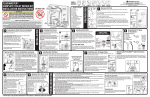
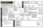
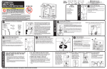
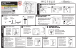
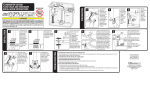
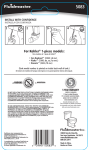
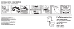
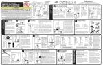
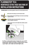
PART# 4-2028, Grev. 4, 10/13
FLUIDMASTER
400ARHR FILL VALVE
INSTALLATION INSTRUCTIONS
TOOLS
NEEDED
®
HOSE CLAMP
REFILL CLIP
WARNING
A
5
F
G
1”
“C.L”
MARK
LOCK
RING
E
Threaded
Shank
Adjusting Tank Water Level
With water turned on, set float cup to
desired level, by turning water level adjustment
screw. When adjusting float cup, flush tank first.
Then make adjustment while tank is filling.
To adjust tank water, turn adjustment screw
clockwise to raise water level or counter
clockwise to lower water level. Once adjusted,
flush toilet and check new level. Repeat if
necessary.
HINT: When you twist adjustment screw 8 times
- float moves 1/2”.
TROUBLESHOOTING
B
IF FILL VALVE DOES NOT TURN ON, WILL NOT
TURN OFF, OR WILL NOT REFILL THE TANK
AFTER THE FLUSH
• Remove top cap and check for debris. If you find debris, or flow
is weak: Inspect lower section of fill valve for partial blockage.
Partial blockage may be at shut off valve or in water supply line
(See “REMOVING THE VALVE CAP ASSEMBLY & FLUSHING OUT
DEBRIS”).
• If fill valve has been in use for some time and/or float cup does not
drop when flushing tank, replace seal with a genuine Fluidmaster 242
seal (See “IF REPLACING SEAL”).
TANK SHOULD
LOOK LIKE THIS
WHEN SET UP IS
COMPLETE
SHANK
WASHER
HINT: Pair with the
patent-pending DUO Flush™
valve to convert your toilet’s
existing single flush valve
to a dual flush valve and to
boost toilet performance
when connected with the
PerforMAX™ fill valve.
(1) Performax™ Fill Valve
(1) Shank Washer
(1) Locknut
(1) Refill Tube
(1) Refill Clip
(1) Roller Clamp
(2) Hose Clamps
Toilet with DUO FLUSH™
Position fill valve in tank, but do not fully install yet. Top
of fill valve MUST be set 3” above overflow pipe. This will
automatically place CRITICAL LEVEL MARK / C.L. Mark,
1” above the top of overflow pipe. Remove fill valve from
tank to adjust height.
Adjust height of fill valve by holding lower shank with right
hand and top of valve with left hand. Twist the lower shank
counter clockwise to increase valve height and clockwise
to decrease valve height. You should hear several “clicks”.
Place valve in tank and check height again. THE CRITICAL
LEVEL MARK, identified by C.L. on valve, MUST be
positioned 1” above top of overflow pipe. This is a
requirement of the Universal Plumbing Code.
Do not move lock ring. It holds the valve body and shank
together under pressure. Do not interchange body with old
shank as leaking can occur.
6
TANK SHOULD
LOOK LIKE THIS
WHEN SET UP IS
COMPLETE
LOCKNUT
Water-Saving Feature: Roller Clamp
Check bowl water level by flushing toilet. If bowl
appears to be full but continues to fill, valve may be overfilling
bowl causing excess water to siphon down trapway. Adjust
amount of water going down into the bowl as follows: Fill the
bowl with a gallon of water. Wait 1 minute until the bowl water
level recedes down and stops. With a pencil, draw a line at
the top of the water level in bowl. Now flush the toilet. If the
valve is still filling and the water is up to the line in the bowl,
then the amount of water going into the bowl is too high and
needs to be adjusted. Adjust the refill by turning the roller
clamp with thumb to the next lower number. Flush the toilet;
adjust until water level in bowl is at the pencil mark when the fill
valve shuts off. If valve shuts off and bowl is not full, adjust by
turning the roller clamp to a higher number. Repeat until water
in bowl is up to line. “O” on roller clamp equals no refill to bowl.
Installing New Fill Valve
3
Place fill valve in tank. Make sure lid will sit on top of tank without
touching valve. Align fill valve nipple to face center of tank. Press down on
shank from inside tank while tightening locknut.
Hand-tighten only. DO NOT OVER TIGHTEN. Over
tightening may crack the fill valve or tank causing
flooding. Make sure the float cup does not touch
the tank walls or tank lever and flush valve.
Attach one end of refill tube to refill clip. Place clip
on right side of overflow pipe. Attach other end of
tube to nipple on fill valve with a slight arch (See
drawing to the right). Cut tube as necessary.
WARNING: Do not shove refill tube down overflow
pipe. This may cause significant water waste.
Squeeze hose clamp. Slide to end of hose and
release.
0
Place Shank
washer onto
threaded
shank of fill
valve. Flat
side up.
C
D
Attach Water Supply Connector
FILL
VALVE
FLUSH
VALVE
Preparing the Fill Valve for Installation
MEASURE
HEIGHT ONLY:
DO NOT INSTALL
*
DUO FLUSH
FLUSH VALVE
LOCK RING
Toilet with 3” Flush Valve
Shank
Washer
Inspect water supply connector. Replace
it if it is worn or over 5 years old to prevent flooding
and property damage.
A. Attach water supply coupling nut to fill valve.
Turn coupling nut clockwise by hand until tight.
WARNING: Do not over tighten the nut as it could
damage fill valve or coupling nut, resulting in
flooding and property damage. Fluidmaster Click
Seal® connector is recommended: A perfect seal
every time without over tightening.
B. Turn on water supply and check for leaks. If you
find leaking at bottom of tank, turn nut just enough
to stop leaking. Then flush toilet to check.
LOCKNUT
OVERFLOW
PIPE
2
LOCKNUT
SHANK
WASHER
Toilet with 2” Flush Valve
Fill Valve Assembly Parts
A) Refill Clip
B) Refill Tube
C) Shank Washer
D) Locknut
E) Threaded Shank
B
F) Roller Clamp
G) Hose Clamps
A
FLAPPER
TANK SHOULD
LOOK LIKE THIS
WHEN SET UP IS
COMPLETE
REFILL TUBE
4
PREPARATION
2
A
4
FLUSH
VALVE
FILL
VALVE FLAPPER
SHANK
WASHER
FILL
VALVE
PARTS
IN THIS KIT:
OVERFLOW PIPE
REFILL CLIP
INSTALLATION
LOCK RING
Remove Old Fill Valve
Remove tank lid. Use pencil to
mark water level of tank. Then follow steps
A-C.
A. Turn off water supply (Clockwise). Flush
toilet and remove excess water from tank
with sponge.
B. Remove water supply coupling nut.
Remove locknut from under tank.
C. Remove fill valve from tank.
LOCK RING
Sponge
FLOAT
CUP
FLOAT
CUP
OVERFLOW
PIPE
LIMITED SEVEN-YEAR EXPRESS WARRANTY
B
REFILL TUBE
REFILL CLIP
Subject to the “Exclusions” set forth below, Fluidmaster Inc. promises to the consumer to repair, or at the option of Fluidmaster Inc. to replace any part
of this plumbing product which proves to be defective in workmanship or materials under normal use for seven years from the date of purchase. All
costs of removal, transportation and reinstallation to obtain warranty service shall be paid by the consumer. During this “Limited Seven Year Express
Warranty,” Fluidmaster Inc. will provide, subject to the “Exclusions” section set forth below, all replacement parts free of charge, necessary to correct
such defects. This “Limited Seven Year Warranty” is null and void if this plumbing product has not been installed and maintained in accordance with all
written instructions accompanying the product, and if non-Fluidmaster Inc. parts are used in installation.
EXCLUSIONS: FLUIDMASTER INC. SHALL NOT BE LIABLE FOR INCIDENTAL OR CONSEQUENTIAL DAMAGES, INCLUDING COSTS OF INSTALLATION, WATER
DAMAGE, PERSONAL INJURY OR FOR ANY DAMAGES RESULTING FROM ABUSE OR MISUSE OF THE PRODUCT, FROM OVERTIGHTENING OR FROM FAILURE
TO INSTALL OR MAINTAIN THIS PLUMBING PRODUCT IN ACCORDANCE WITH THE WRITTEN INSTRUCTIONS, INCLUDING USE OF NON-FLUIDMASTER PARTS.
DO NOT USE IN-TANK DROP-IN TOILET BOWL CLEANERS CONTAINING BLEACH OR CHLORINE. USE OF SUCH PRODUCTS WILL RESULT IN DAMAGE TO TANK
COMPONENTS AND MAY CAUSE FLOODING AND PROPERTY DAMAGE. USE OF SUCH PRODUCTS WILL VOID THIS WARRANTY.
1
ROLLER CLAMP
ROLLER CLAMP
HOSE CLAMP
FLOAT
CUP
DO NOT USE IN-TANK DROP-IN TOILET BOWL CLEANERS CONTAINING BLEACH OR
CHLORINE. Use of such products will: (1) RESULT IN DAMAGE to tank components and MAY
CAUSE FLOODING and PROPERTY DAMAGE and (2) VOID FLUIDMASTER WARRANTY.
Fluidmaster Flush 'n Sparkle Toilet Bowl Cleaning System is recommended for those
choosing to use in-tank bowl cleaners and WILL NOT VOID the FLUIDMASTER WARRANTY
because it will not damage the components. DO NOT overtighten nuts or tank/bowl may crack. Always use quality
Fluidmaster parts when installing or repairing. Fluidmaster will not be responsible or liable for use of non-Fluidmaster parts
during installation or repair.
C
TANK
LEVER
REFILL TUBE
6
ROLLER CLAMP
8
TANK
LEVER
DO NOT USE
Scissors
30800 Rancho Viejo Road, San Juan Capistrano, CA 92675
www.Fluidmaster.com • 800-631-2011
Contact Fluidmaster for troubleshooting help or visit www.fluidmaster.com
M-F 5:30 am - 5:00 pm PST.
Hose
Clamps
7
Correct set up of refill
tube and refill clip to
overflow pipe
REFILL HOSE
REFILL CLIP
NIPPLE
Code Compliance
Once fill valve is installed, ensure overflow
pipe and water level of tank are correctly set.
D
1. THE TOP OF OVERFLOW PIPE (A) must be
minimum of 1" below TANK LEVER HOLE (B).
2. WATER LEVEL (C) is set below top of Overflow
Pipe (Fluidmaster recommends 1/2”).
3. THE CRITICAL LEVEL MARK / C.L. Mark (D)
identified by C.L. on fill valve must be positioned 1”
above top of overflow pipe. This is a requirement of
the Universal Plumbing Code.
B
WATER
LEVEL
Code Compliance helps protect your home &
drinking water supply.
Removing Valve Cap Assembly, Flushing Out Debris, Replacing Seal, & Replacing Valve Cap Assembly
• This indicates the tank is losing water. The fill valve is refilling lost water.
Clean flapper and drain seat. If leak continues change flush valve. Install
Fluidmaster 507AKR, 540AKR or 555C kit.
Removing Valve Cap Assembly
IF WATER LEVEL IN BOWL IS TOO LOW
• Make sure the refill tube is supplying water down overflow pipe.
• Water level in tank may be too low. Raise water level to 1/2” below top of
overflow pipe (See “ADJUSTING TANK WATER LEVEL”). You may have
to lengthen the fill valve in order to increase the water level in tank (See
“PREPARING THE FILL VALVE FOR INSTALLATION”).
• Flapper may be closing too soon. Give flapper chain approximately 1/2”
of slack.
– Please keep a copy of these instructions on the property in which the product was installed.
OVERFLOW
PIPE
FILL
VALVE
IF FILL VALVE TURNS ON AND OFF BY ITSELF
Turn off water supply & flush
out tank. Push float up with
right hand (see picture). Grip
and hold shaft under float with
right hand. With left hand,
twist cap and lever counter
clockwise 1/8th of a turn to
unlock the top cap. Pressing
down on top may be helpful
with older valves. Let cap
assembly hang on float cup.
Flushing Out Debris
Hold cup upside down over
uncapped valve to prevent
splashing. Turn water supply
on and off a few times. Turn
water supply off when putting
cap back on valve.
If Replacing
Seal
Replacing Valve Cap
A. Place cap assembly on top of gray
valve body by aligning cap arm and
adjustment rod next to refill tube.
B. Press down on top cap while rotating
top & arm clockwise to locked position.
SEAL
LOCATION
If Replacing Seal:
Use only a genuine
Fluidmaster 242 seal.
242
SEAL
A
C
A
B