1
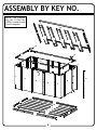
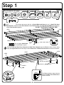
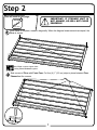
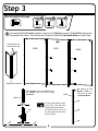
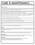
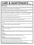
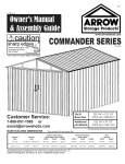
01O
01L
718531113
Owner’s Manual
& Assembly Guide
R
TM
www.arrowsheds.com
Customer Service:
1-800-851-1085
or
[email protected]
Gloves must be worn
at all times to reduce
risk of injury!
PATENT PENDING
UNIT DIMENSIONS
Storage
Area
Exterior Dimensions
(Lid Edge to Lid Edge)
Interior Dimensions
(Wall to Wall)
Width
Depth
Height
Width
Depth
Height
10 Sq. Ft.
21 Cu. Ft.
57 3/8”
29 3/4”
28”
53 3/4”
26 1/16”
26”
0,9 m2
0,6 m3
145,7 cm
75,6 cm
71,1 cm
136,5 cm
66,2 cm
66 cm
* See Inside for Detailed Safety Information.
BEFORE YOU BEGIN...
02L
Safety precautions MUST be followed at all times throughout the construction of your Storage Unit!
•Care must be taken when handling various pieces of your Storage Unit since
many contain sharp edges. Please wear work gloves, eye protection and long
sleeves when assembling or performing any maintenance on your Storage
Unit.
•Practice caution with the tools being used in the assembly of your Storage
Unit. Be especially familiar with the operation of all power tools.
•Keep children and pets away from the worksite during construction. Do not
allow children to help with assembly.
•Do NOT attempt to assemble your Storage Unit on a windy day. The large
panels can catch the wind like a “sail”, causing them to be whipped around
making construction difficult and unsafe.
•If possible, two people should work together to assemble your Storage Unit.
This will make assembly faster and easier.
Reading and following all steps carefully will help make assembly quicker and easier. Before you begin
assembly, be sure to confirm that all the parts for your Storage Unit are present using the checklist on
pages 3 and 4. If parts are missing, include the model number of your storage unit and contact Customer
Service at 1-800-851-1085 or online at [email protected].
NOT RECOMMENDED FOR STORAGE OF CORROSIVE CHEMICALS OR PRODUCTS
Below is a list of things you will need to assemble your Storage Unit.
WHAT YOU NEED
RECOMMENDED TIME SAVERS
2
•
•
•
•
Work Gloves
Safety Glasses
No. 2 Phillips Screwdriver (Magnetic Tip Preferred)
Pliers
•
•
•
Power Drill (Cordless, Variable Speed)
Nut Driver or Wrench
Awl (to help align holes)
HARDWARE LIST...
Key
No.
Part
No.
Part
Description
Qty.
1
69971
Hex Nut (#8-32)
30
2
69960
Small Bolt (#8-32 x 3/8) (10 mm)
22
3
69972
Small Screw (#8AB x 5/16) (8 mm)
58
4
69972-60 Small Screw (Painted) (#8AB x 5/16) (8 mm)
6
5
69973
Large Screw (#10AB X 1/2) (13 mm)
27
6
69974
Flat Head Bolt (#8-32 X 1/2) (13 mm)
6
7
69958
Long Screw (#6AB X 7/8) (22 mm)
8
8
69962
Small Flat Head Bolt (#6-32 X 7/16) (11 mm)
1
9
69961
Hex Nut (#6-32)
1
10
66676
Push Pin
46
11
66803
Flat Head Self Tapping Screw (#8A X 1/2) (13 mm)
3
12
69959
#8 Lock Washer
2
13
69953
Plastic Foot
9
14
66798
Foam Tape
1
15
66784
Offset Hinge
3
16
69965
Lid Stay
3
17
69966
End Cap Strap
6
18
69967
Lid Catch
1
19
66792
Locking T-Handle
1
20
69968
Latch
1
21
66801
Plastic Spacer
1
22
60H
Corner Cap
2
03O
1
2
List
Part Numbers
Part Number
1. Each part has an identifying part number on it.
2. Part Numbers are referenced in each step.
3. Unpainted parts have a stamped in number and painted
parts have a number that is inked on.
11/32 Hex.
#2 Phillips
PSS 5
4
#2 Phillips
7
10
5/16 Hex.
#2 Phillips
LS 6
PP 11
3
FSS
#2 Phillips
14
15
16
17
18
19
20
21
22
#8 Lock
Washer
Confirm that all hardware and parts
are present before attempting to
assemble your Storage Unit.
For missing parts contact Customer
Service. Do not return to store.
Customer Service:
Remove inked on numbers with soap and water after assembly.
FB
#2 Phillips
13
12
SS
#2 Phillips #2 Phillips
LNS 8
SFB
#2 Phillips
9
SB 3
1-800-851-1085
or
[email protected]
PARTS LIST...
Key
No.
1
2
3
4
5
6
7
8
9
10
11
12
13
14
15
16
17
Part
No.
10682
10683
10685
10686
10687
10688
10689
10690
10691
10692
10693
10694
10695
6481
10697
10698
10696
Part
Description
Floor Section
Front & Rear Floor Section
Front & Rear Floor Channel
Side Floor Channel
Lid Handle Panel
Wall Panel
Corner Panel
U-Splice
Lid Stay Brace
Lid Handle Brace
Front Top Channel
Rear Top Channel
Side Top Channel
Gusset
Lid Support
Lid Panel
Lid End Cap
04L
Qty.
List
4
2
2
2
1
7
4
12
3
1
1
1
2
2
5
1
2
Selected End Views by Key No.
1
2
Unpainted
4
3
8
Painted/
Unpainted
10
Unpainted
13
Painted/
Unpainted
Painted/
Unpainted
Unpainted
9
Unpainted
11
Painted/
Unpainted
14
Unpainted
Unpainted
12
Painted/
Unpainted
15
Unpainted
17
At the top of each page you will see
one or more Part Cues like the one
to the right. These Part Cues are
designed to help you quickly identify
the parts needed for each step.
Quantity Needed
Part No.
End View
Part Name
10697 5
Painted/
Unpainted
Lid Support
Various fasteners are used throughout the
construction of your storage unit. In each step
you will see the abbreviations listed below
used in the illustrations to help you identify
which fastener to use.
SB - Small Bolt
SS - Small Screw
LS - Large Screw
PP - Push Pin
SB
FB - Flat Head Bolt
PSS- Painted Small Screw
LNS- Long Screw
SB
SFB- Small Flat Head Bolt
FSS- Flat Head Self Tapping Screw
The fasteners used in each step are shown actual
size at the top of each page. If you are unsure
which fastener to use, hold it up to the picture and
use the one that matches.
64
QTY 18
ASSEMBLY BY KEY NO.
05L
NOTE: The U-Splice,
Key No. 8 (Part No.
10690) is used at each
Panel connection.
16
17
15
15
15
15
15
17
14
13
14
12
7
6
11
9
6
13
6
9
6
9
10
7
6
7
6
5
6
7
4
3
3
2
1
5
1
1
1
2
4
8
Step 1
You will need for this page:
SB
SFB
(QTY: 4)
(QTY: 1)
06L
69953 9
Plastic Foot
10682 4
Floor Section
10683 2
10685 2
10686 2
F/R Floor
Section
F/R Floor
Channel
Side Floor
Channel
LNS
1
(QTY: 8)
Assemble the Floor as shown and secure with four (4) Small Bolts and Nuts and one (1) Small Flat Head
Bolt and Nut in between middle Floor Section. Add a Plastic Foot to the Small Flat head Bolt when attaching
middle Floor Sections together.
DO NOT TIGHTEN BOLTS AT THIS TIME.
10682
10683
Do not tighten Small Bolts
until after Floor is square.
2
69953
SB
10683
10682
SFB
SB
SB
Slide the Front and Rear Floor Channels and Side Floor Channels onto the Floor as shown. Secure using
eight (8) Long Screws where holes align. At each Screw attach a Plastic Foot. Screws must enter from bottom.
10686
10685
10686
69953
10685
69953
LNS
69953
LNS
LNS
10685
10686
10685
10683
66
The Floor should be aligned with the
Front and Rear Floor Channels as
shown to the left.
Step 2
07L
You will need for this page:
IMPORTANT: IF STORAGE UNIT IS
NOT SQUARE, LID WILL NOT CLOSE
PROPERLY!
66798 1
Foam Tape
1
Once Floor is complete, measure diagonally. When the diagonal measurements are equal, the
Floor is square.
After Floor is square tighten bolts
holding Floor Sections together.
2
Seal corners of Floor with Foam Tape. Cut four (4) 1” (2,5 cm) strips to place between Floor
Channels at the corners.
7
Step 3
08L
You will need for this page:
PP
(QTY: 6)
1
10687 1
10688 2
Lid Handle
Panel
Wall Panel
10690 2
U-Splice
Pre-assemble Front Panels together using two (2) U-Splices and six (6) Push Pins leaving the
top paired hole vacant. These holes will be used to attach the Lid Handle Brace in a later step.
Paired holes and
hinge holes at top.
10688
10687
10688
Single hole at bottom.
Slide U-Splice over the Panels where
the Panels meet and secure using
Push Pins.
Except on Lid
Handle Panel to
allow room to install
Lid Handle Brace.
PP
10690
10690
PP
To help with aligning holes,
use an awl. This will make
inserting push pins easier.
If push pins will not go in all
the way, lightly tap push pin
with a hammer.
PP
10
6
88
PP
7
68
10
PP
8
Step 4
09L
You will need for this page:
10688 3
PP
(QTY: 8)
1
Wall Panel
10690 2
U-Splice
Pre-assemble Back Panels together using two (2) U-Splices and eight (8) Push Pins.
Paired holes and
hinge holes at top.
10688
10688
10688
Single hole at bottom.
PP
10690
Slide U-Splice over the Panels where
the Panels meet and secure using
Push Pins.
10690
PP
To help with aligning holes,
use an awl. This will make
inserting push pins easier.
If push pins will not go in all
the way, lightly tap push pin
with a hammer.
PP
10
8
68
PP
8
68
10
PP
9
Step 5
You will need for this page:
PP
(QTY: 16)
1
10L
10688 2
Wall Panel
10689 4
Corner Panel
10690 4
U-Splice
Pre-assemble Side Panels together using two (2) U-Splices and eight (8) Push Pins. Make
two (2) assemblies.
Paired holes and
hinge holes at top.
10689
10688
10689
Single hole at bottom.
PP
10690
Slide U-Splice over the Panels where
the Panels meet and secure using
Push Pins.
10690
PP
To help with aligning holes,
use an awl. This will make
inserting push pins easier.
If push pins will not go in all
the way, lightly tap push pin
with a hammer.
PP
8
1
8
06
PP
PP
89
6
10
10
Step 6
11L
You will need for this page:
SB
LS
(QTY: 6)
1
(QTY: 6)
10690 4
PP
Assemblies from steps 3,4,&5:
• A Front Panel Assembly (1)
• B Back Panel Assembly (1)
• C Side Panel Assembly (2)
U-Splice
(QTY: 16)
Position each Panel Assembly as shown and secure to the Floor with one (1) Large Screw in
the bottom leg of each Front and Rear Panel and Small Bolt in each Side Panel.
Paired holes and
hinge holes at top.
C
B
A
C
SB
LS
Single hole at bottom.
SB
2
Secure Panel Assemblies together using four (4) U-Splice and sixteen (16) Push Pins.
PP
10690
Slide U-Splice over the Panels where
the Panels meet and secure using
Push Pins.
10690
PP
To help with aligning holes,
use an awl. This will make
inserting push pins easier.
If push pins will not go in all
the way, lightly tap push pin
with a hammer.
PP
8
1
8
06
PP
7
1
8
06
PP
11
Step 7
You will need for this page:
SB
(QTY: 6)
1
12O
69965 3
Lid Stay
10691 3
Lid Stay Brace
Pre-assemble the Lid Stay to the Lid Stay Brace using two (2) Small Bolts and Nuts. Make
three (3) assemblies.
SB
69965
10691
2
Place the two (2) outside Lid Stay/Brace Assemblies into Back Corner Panel. DO NOT
install, just set in place as shown and set third assembly aside for now.
Rear Corner Panel
12
Step 8
13L
You will need for this page:
SS
SB
(QTY:14)
(QTY: 4)
1
10693 1
10694 1
Front Top
Channel
Rear Top
Channel
10695 2
Side Channel
6481
2
Gusset
2
60H
Corner Cap
First install top channels starting with Front and Rear Channels, then install Side Channels
using ten (10) Small Screws.
When installing top channels, start on inside lip of
wall panels then rotate to the outside.
SS
SS
SS
10695
SS
10694
SS
SS
SS
SS
10695
SS
10693
2
SS
Install Corner Caps on front corners using two (2) Small Bolts. Install Gussets on back corners
using four (4) Small Screws and two (2) Small Bolts.
SB
SS
SS
6481
SS
SB
SB
SS
60H
SB
13
Step 9
You will need for this page:
SS
(QTY: 2)
1
14L
10692 1
66792 1
Lid Handle
Brace
Locking
T-Handle
Bend end flaps down as shown
before installation.
10692
Install Lid Handle Brace to Lid Handle Panel as shown
using two (2) Small Screws.
10687
SS
SS
10692
Slide Lid Handle Brace over
U-Splice and secure using
Small Screws.
10692
2
Install Locking T-Handle using two (2) Long Bolts which are
packed with Locking T-Handle.
66792
Packed with Locking
“T”Handle
6
14
Step 10
15L
You will need for this page:
SS
• Lid Stay/Brace Assemblies (3)
(QTY: 12)
1
Install three (3) Lid Stay/Brace Assemblies into the
back panels by angling them into place; one in each
Back Corner Panel and one in Middle Panel.
SS
2
Secure each Lid Stay/Brace Assembly using four (4)
Small Screws. Two on top and two on botton of brace.
First attach bottom of Lid Stay/
Brace Assembly, then attach top
of the Lid Stay/Brace Assembly.
SS
6
15
Step 11
16O
You will need for this page:
69959
SB
(QTY: 2)
1
(QTY: 2)
69967 1
10697 1
Lid Catch
Lid Support
For the middle Lid Support attach the Lid Catch using two (2) Small Bolts, Lock Washer,
and four (4) Nuts.
69967
#8 Lock Washer
10697
SB
SB
Loosen top nut to adjust fit
between Latch and Lid Catch.
16
Step 12
You will need for this page:
LS
(QTY: 12)
1
PSS
SS
(QTY: 24)
(QTY: 6)
17O
10697 5
Lid Support
10696 2
69966 6
End Cap
Strap
Lid End Cap
10698 1
Lid Panel
Start lid assembly by attaching five (5) Lid Supports to the Lid Panel using twenty (20) Small
Screws. Make sure all Lid Supports are facing the same way with middle Lid Support having
the Lid Catch mounted to it.
SS
Lid
Catch
Hinge holes
at
the bottom.
SS
2
Attach the Lid End Caps and End Cap Straps to the Lid Panel using twelve (12) Large
Screws, four (4) Small Screws, and six (6) Painted Small Screws.
SS
LS
LS
PSS
SS
17
Step 13
18L
You will need for this page:
LS
(QTY: 9)
1
(QTY: 6)
66784 3
FSS
FB
SS
(QTY: 3)
(QTY: 6)
Offset Hinge
Install three (3) Hinges using six (6) Flat Head Bolts and three (3) Flat Head Self Tapping
Screws.
FB
FB
FSS
FB
Inside
2
3
Secure lid to base by attaching all three (3)
Hinges to lid using nine (9) Large Screws.
Attach the three (3) Lid Stays to the
Lid using six (6) Small Screws.
SS
LS
18
Outside
Step 14
You will need for this page:
19O
69968
Latch
1
1
66801
1
Plastic Spacer
Install Latch and Plastic Spacer to the inside of the
Locking T-Handle. Secure with Push Nut found in
the Locking T-handle packaging.
Pay careful attention
to position of Latch.
2
Adjust Lid Catch as needed to ensure Latch
completely locks into place as shown below.
Lid Catch
Latch
Loosen top nut to adjust fit
between Latch and Lid Catch.
19
Push Nut
69968
66801
CARE & MAINTENANCE...
20L
Exterior Care:
For a long lasting finish clean and wax the exterior surface. We recommend washing with a mild soap
solution. DO NOT use power washing to clean your storage unit. Using a spray automotive type wax
periodically on the exterior is highly recommended if you are in a high humidity or coastal climate region.
Combustibles must be stored in air tight containers designed for combustible storage.
NOT RECOMMENDED FOR STORAGE OF CORROSIVE CHEMICALS OR PRODUCTS
Rust protection precautions may help to stop rust from developing, or stop it quickly as soon as it appears.
• Avoid nicking or scraping the coating surface, inside and out.
• Keep storage unit free of debris and leaves which may accumulate and retain moisture. These can do
double damage since they give off acid as they decay.
• Touch up scrapes or nicks and any area of visible rust as soon as possible. Make sure the surface is
free of moisture, oils, dirt or grime and then apply an even film of high quality touch-up paint.
• Various paint manufacturers provide products for rust treatment and coverage. If surface rust does
appear on your storage unit we recommend treating those areas as soon as possible, following the paint
supplier of your choice instructions.
• Our customer service department can provide the paint tinting formula for matching the color of your
storage unit. We also have touch-up paint available for repairing small nicks and scratches.
Fasteners:
Use all washers supplied to protect against weather infiltration and to protect the metal from being
scratched by the screws. Regularly check screws, bolts, nuts, etc., and retighten as necessary.
General:
• Wash off inked part numbers on coated panels with soap and water.
• Silicone caulking may be used for watertight seals throughout the storage unit.
Please note, Manufacturer cannot be held responsible for any consequences due to storage units that
are not installed per these instructions, or for damage due to weather conditions or acts of God.
Keep these assembly instructions and owner’s manual for future reference.