1
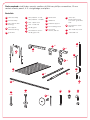
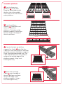
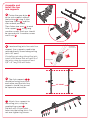
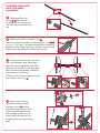
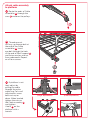
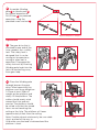
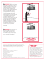
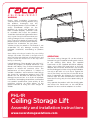
WARNING
Please read installation instructions
carefully prior to installing. Before using
the product, thoroughly test the
fully-weighted product (up to 250lbs of
evenly distributed weight on the
platform) to ensure the product has
been installed properly. Fasteners used
to assemble and install the product
should be checked and tightened at least
once a year. Do not install more than one
Ceiling Storage Lift on a common ceiling
joist. If you are in doubt of installing this
product, please contact a professional to
perform the installation. Do not allow
children to play on product. ITW Brands is not
responsible for any damage resulting from
improper installation, overloading or product
failure.
Note: When choosing a location for your Ceiling
Storage Lift, make sure there is enough room to
raise and lower the platform. All obstructions and
people should be moved out of the way when
raising or lowering.
Limited Warranty: These products are sold “as is”
without any express or implied warranties. ITW
Brands sole liability, if any, shall be to replace this
product or refund the purchase price. The
performance of these products is subject to
variable conditions and maximum load ratings
are shown for comparison purposes only. ITW
Brands will not be liable for personal injury or
damage to possessions as a result of improper
installation, overloading the platform, unintended
use, product modification, poor quality of the
mounting surfaces, or other abuses of the
product outside of lifting the static weight of
250lbs.
OPERATION
The Racor Ceiling Storage Lift can be raised or
lowered using the supplied winding pole. Attach
to the winding pole either the supplied
hand-crank or the supplied drill/driver adapter.
When using either the hand-crank or the drill
adapter, be sure these attachments are secured
to the winding pole. When using the drill adapter,
use only a drill with a ½ inch chuck. Tighten the
chuck jaws firmly on the flats of the drill driver
prior to operation by following the instruction
manual from the drill manufacturer. Raise and
lower the lift using only the low speed setting of
the drill.
Only operate the product with the winding pole
and either the hand-crank or the drill/driver
adapter. Do not use other adaptors or sockets.
PHL-1R
Ceiling Storage Lift
Assembly and installation instructions
www.racorstoragesolutions.com
Tools required: stud finder, wrench, cordless drill/driver, phillips screwdriver, 10 mm
socket wrench, pencil, 4 ft. straightedge, and pliers.
Parts list:
A
cable assembly
B
arm assembly
C
D
E
axle support with
bushing
axle support
without bushing
gear drive
F
wire platform - 2 side,
wire platform - 1 middle
G
axle - square end
H
axle - round end
I
winding pole
J
short machine screw winding pole nut
K
hand-crank
L
drill driver
M
platform support
N
hex head lag screw
O
hex screw,
washer, and nut
P
cotter pin,
fender washer, and
hex screw - gear drive
side
Q
long machine screw
and nut
R
allen head cap screw
S
J-bolt and nut
I
C x1
x1
D x1
B
A
x4
x2
J
x1
E x1
F
K
x3
x1
H x1
G x1
L
M x2
x1
N
x20
O
Q
R
S
x2
x8
x4
x12
P x1
Assemble platform
1
Lay the three wire
platforms F on the floor.
Place the wire platform with
the four tabs in the middle.
These tabs will fit into the two
outer platforms.
2
Lay the platform
supports M underneath and
across all three wire
platforms. The holes on the
platform supports should face
towards the outside edge of
the wire platforms.
3
Locate the holes on platform
supports for J-bolts S and slide four
J-bolts thru the wire platforms and holes
on the four corners of platform supports.
Place J-bolt between double wire. The
J-bolt should hook over wire platform
and over the outside edge of the
platform support. Using a nut,
hand-tighten only.
4
Place the remaining
J-bolts S over the edge of
the wire platforms and over
the outside edge of the
platform supports. Using a
nut, hand-tighten only.
Assemble and
install the two
arm supports
5
Fasten the gear drive E
to the axle support without
the bushing D , using 4 allen
head cap screws R , and the
allen wrench provided.
Then fasten two arms B to each
Axle support C D , using long
machine screws. Each arm should
be secured with 2 machine screws
and 2 nuts Q .
6
Locate ceiling joists for each Arm
support. Arm supports need to be
secured directly to and along ceiling
joists 48” apart.
If installing not along the ceiling joist,
install a 2x4 board that will span 4 of
the joists using lag screws at least
3/8” x 5” long. Pre-drill holes.
stud finder
(not included)
ceiling joist
7
The Axle supports C D
should be facing away from
each other and the two Arm
supports should line up and
be square to each other.
8
Attach Arm supports to
the ceiling joist, using the
supplied lag screws N .
Pre-drill with 1/8 inch pilot
holes into the ceiling joists. Do
not over tighten lag screws.
48" APART
Assemble and install
axles and cable
assemblies
9
Slide together the
Axles G H but do not
assemble with screws yet.
The bolt holes should be in
line.
10 Slide each cable assembly ring
A
over the square shoulder at each end of Axle G H ,
as far as it will go. The cable assemblies should be
placed on the square portions of the Axle and the
cable ends should face towards the center.
11 Insert one end of the Axle into
the Axle Support and slide them
apart to insert the other end. The
square end should fit into the gear
drive and the round end should fit
into the plastic bushing.
Fasten the Axle ends together with
two screws and nuts O .
12 Secure the Axle by
installing fender washer
and hex screw P on the
end of the gear drive. Then,
insert the provided cotter
pin through a hole on the
other end and secure it by
bending the two protruding
ends.
Attach cable assembly
to platform
13 Route the ends of Cable
1
assemblies A through the
arms B and over the pulleys.
2
14 Thread one nut
half-way up the eye-bolt at
the end of the Cable
assemblies A . Insert
eye-bolt through the hole
at the end of Shelf support
and fasten washer and nut
from underneath. Repeat
on all four corners.
M
15 If platform is not
level, adjust by
pulling the cable
through the nylon
cable ring. For small
adjustments, move
both nuts up or
down. When leveled,
tighten the nuts on
the Cable assembly A
and tighten
J-bolts S on the
platform with a
wrench.
(Large adjustment)
(Small adjustment)
16 Assemble Winding
pole I to Hand-crank K
for manual operation or
Drill/Driver L for powered
operation, using the
provided screw and nut J .
Optional Drill/Driver Adaptor
Operation
17 The gear drive that is
attached to one end of the
Axle supports has a safety
lock. The safety lock is
designed that it can be
swung out to operate or
swung-in when not in
operation. Disengage the
safety lock out by inserting
Winding pole hook into the
lock slot and pulling away
from gear loop.
18 Place the Winding pole
through loop on the gear
drive. When operating, the
platform must have weight on
it. Place at least 25lbs of
weight on the platform and
slowly lift the platform. The
cables should evenly wind
around the Axle and not
overlap. The platform should
be raised such that the stored
items are not touching the
ceiling or the Axle. The platform will lower
approximately 8 feet from the ceiling.
Note: If cables do not wind evenly, be sure cable
ring is pushed all the way in.
Also make sure the load is balanced and the
platform is level.
GOOD
BAD
WARNING! Before raising or
lowering the platform, clear all
people and obstructions from
under the platform in a 6ft x
6ft area. When loading the
platform, the weight should be
evenly distributed. Test by
raising platform to ceiling.
Always engage safety lock
when platform is raised. Do not
stand under platform while
raising or lowering. The
platform should remain flat and
not tilt more than 10 degrees
during operation. Failure to
operate the product properly
could cause objects to fall off
the platform and result in
serious injury or product
damage.
WARNING! Do not park car
or walk under for at least 1
hour, to be sure that unit is
installed securely. Never play
on or around the product.
Limited Warranty: These products are sold “as is” without any express or implied
warranties. ITW Brands’ sole liability, if any, shall be to replace this product or refund
the purchase price. The performance of these products is subject to variable
conditions and maximum load ratings are shown for comparison purposes only.
PHL-1R
Made in China
ITW Brands, A division of Illinois Tool Works Inc.
955 National Parkway, Suite 95500
Schaumburg, IL 60173
800-783-7725
www.RacorStorageSolutions.com
Email: [email protected]
© 2013 Illinois Tool Works Inc.
Racor and Racor logo are registered trademarks of Illinois Tool Works Inc.
HOME
STORAGE
PRODUCTS
Thank you for purchasing this product.
Racor storage and organizational
solutions will inspire and put you back
in control of your space. Racor has the
largest variety of solutions to organize
and store bikes, sports equipment,
lawn and garden supplies, bulky items
like ladders and totes, and clutter items
like tools. Please visit
www.RacorStorageSolutions.com for
other great organizational products.