1
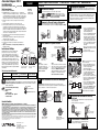
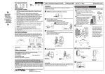
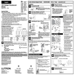
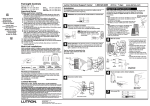
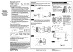
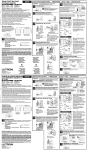
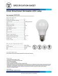
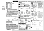
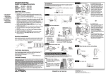
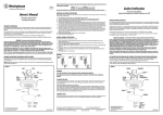
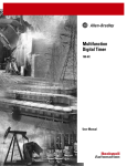
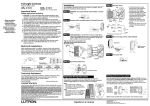
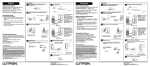
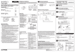
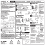
120 V Halogen / Incandescent
Dimmer
Rated at 120 V
English
Important Notes
Please read before installing.
1. Caution: Use only with permanently-installed 120 V halogen or incandescent fixtures. To avoid overheating and possible damage to other equipment,
do not use to control receptacles, fluorescent lighting fixtures, motor-driven
appliances, or transformer-supplied appliances.
2. Install in accordance with all national and local electrical codes.
3. Only one dimmer can be used in a 3-way circuit.
4. When no “grounding means” exist within the wallbox then the
NEC® 2008, Article 404.9 allows a dimmer without a grounding connection
to be installed as a replacement, as long as a plastic, noncombustible
wallplate is used. For this type of installation, cap or remove the green
ground wire on the dimmer and use an appropriate wallplate such as
Claro® or Fassada® series wallplates by Lutron.
5. For new installations, install a test switch before installing the dimmer.
6. Protect dimmer from dust and dirt when painting or spackling.
7. Recommended minimum load is 40 W.
8. It is normal for the dimmer to feel warm to the touch during operation.
9. Clean dimmer with a soft damp cloth only. Do not use any chemical
cleaners.
Models:
DV-603PG
DVW-603PG
DVSC-603PG
Dimmer Rating
600 W
No sides
removed
600 W
1
24 hrs / 7 days
5
Turning OFF Power.
• Turn power OFF at circuit breaker (or remove fuse).
Warning: Shock Hazard. May result in serious
injury or death. Turn off power at circuit
breaker before installing the unit.
2
Removing Wallplate and Switch.
www.lutron.com
Wiring the Dimmer.
• For installations involving more than one control in a wallbox, refer to the
section on Multigang Installations before beginning.
Helpful Hints:
1. The red/white wire is not used in a single-pole application. Twist a wire
connector onto this wire if the Dimmer is used for a single-pole application.
2. Dimmer wire locations will vary by product. Reference wires by color, not location.
5a - Single-Pole Wiring
• Remove wallplate and switch mounting screws.
• Carefully remove switch from wall (do not remove wires).
Black
• Connect the green dimmer ground
wire to the bare copper or green
ground wire in the wallbox.
(See Important Note 4.)
Red
3
Multigang Installations
Dimmer Capacity Chart
1.800.523.9466
Installation
60 Hz 600 W
When installing more than one control in the same
wallbox, it may be necessary to remove all inner
side sections prior to wiring (see diagram). If
pre-installed, remove the Lutron® wallplate and
wallplate adapter from dimmer. Using pliers, bend
side section up and down until it breaks off.
Repeat for each side section to be removed.
Removal of dimmer side sections reduces
maximum load capacity. Refer to chart below
for maximum dimmer capacity.
Lutron Technical Support Center
Identifying the Type of Circuit.
Green
Different-colored screw (COMMON).
Actual location may vary.
Do Not Remove
Outside Sections
Or
Ground (bare
copper or
green wire)
• Connect the black dimmer wire to
one of the wires removed from the
switch. If you had taped together
two wires (see step 4), connect both
wires to the black dimmer wire and
remove the tape.
Ground
Red/White
• Connect the red dimmer wire to
the other wire removed from
the switch.
Live
Black
Red
120 V~
60 Hz
Green
Red/White
Dimmer
Ground
Light
• Twist a wire connector onto the
red/white dimmer wire; this wire
does not get connected.
This operation has now been completed.
Ground (bare copper or
green wire)
Each Control Has Inside
Sections Removed
1 side
removed
500 W
Middle Control Has Two
Side Sections Removed
2 sides
removed
400 W
Technical Assistance
If you have questions concerning the installation or operation of this product, call the
Lutron Technical Support Center. Please provide exact model number when calling.
U.S.A. and Canada (24 hrs/7days)
1.800.523.9466
México
+1.888.235.2910
Other countries 8am – 8pm ET
+1.610.282.3800
Fax +1.610.282.6311
Single-Pole:
Insulated wires connected to
two screws of the same color. Or
Replace with a Single-Pole
dimmer.
See Step 5a when wiring.
4
Tag
3-Way:
Insulated wires connected to three screws. Two
screws are the same color and the other is a different color (COMMON), not green. Tag the wire that is
connected to the different color screw to identify it
when rewiring. Replace with a 3-Way dimmer.
See Step 5b when wiring.
Note: Only one dimmer can be used
in a 3-way circuit.
5b - 3-Way Wiring
Black
• Connect the green dimmer ground
wire to the bare copper or green
ground wire in the wallbox.
(See Important Note 4.)
Tape
Red
Disconnecting Switch Wires.
Green
Important Note: Your wall switch may have one continuous wire attached to the same
screw (see illustrations below for examples). Tape these two wires together before
disconnecting.
http://www.lutron.com
One wire in the
backwired hole
and one to the
screw.
Limited Warranty
One continuous
wire to the
screw.
Ground
Red/White
Live Tag Black
120 V~ Green
60 Hz
Ground
• Connect the red dimmer wire to
one of the remaining wires
removed from the switch.
Red
Red/White
Dimmer
3-Way
Switch
Light
(Valid only in U.S.A., Canada, Puerto Rico, and the Caribbean.)
• Connect the black dimmer wire
to the wire removed from the
different-colored screw on the
switch (taped wire). If you had
taped together two wires
(see step 4), connect both wires
to the black dimmer wire.
Remove tape from wire.
• Connect the red/white dimmer
wire to the other remaining wire
removed from the switch.
This operation has now been completed.
Tag
Lutron will, at its option, repair or replace any unit that is defective in materials or manufacture within one year after purchase. For warranty service,
return unit to place of purchase or mail to Lutron at 7200 Suter Rd., Coopersburg, PA 18036-1299, postage pre-paid.
THIS WARRANTY IS IN LIEU OF ALL OTHER EXPRESS WARRANTIES, AND THE IMPLIED WARRANTY OF MERCHANTABILITY IS LIMITED TO ONE
YEAR FROM PURCHASE. THIS WARRANTY DOES NOT COVER THE COST OF INSTALLATION, REMOVAL OR REINSTALLATION, OR DAMAGE RESULTING FROM MISUSE, ABUSE, OR DAMAGE FROM IMPROPER WIRING OR INSTALLATION. THIS WARRANTY DOES NOT COVER INCIDENTAL OR CONSEQUENTIAL DAMAGES. LUTRON’S LIABILITY ON ANY CLAIM FOR DAMAGES ARISING OUT OF OR IN CONNECTION WITH THE MANUFACTURE,
SALE, INSTALLATION, DELIVERY, OR USE OF THE UNIT SHALL NEVER EXCEED THE PURCHASE PRICE OF THE UNIT.
This warranty gives you specific legal rights, and you may have other rights which vary from state to state. Some states do not allow the exclusion or
limitation of incidental or consequential damages, or limitation on
how long an implied warranty may last, so the above limitations
may not apply to you.
This product may be covered by one or more of the following
U.S. patents: 5,207,317; 5,637,930; 6,005,308; D364,141; and
corresponding foreign patents. Lutron, Fassada, and Claro are
registered trademarks of Lutron Electronics Co., Inc. NEC is a
registered trademark of National Fire Protection Association,
Quincy, Massachusetts. © 2009 Lutron Electronics Co., Inc.
6
Mounting Dimmer to Wallbox.
• Form wires carefully into the wallbox, mount and align dimmer.
• Install wallplate.
Screw Terminals:
Turn screws to
loosen.
Start screws.
Align dimmer and
tighten screws.
Push-In Terminals:
Insert screwdriver. Pull
wire out.
030-1109
Lutron Electronics Co., Inc.
7200 Suter Road
Coopersburg, PA 18036-1299, U.S.A.
Made and printed in U.S.A.
9/09 P/N 030-1109 Rev. A
030-1109
7
Turning ON Power.
• Turn power ON at circuit breaker (or replace fuse).
Atenuador Halógeno 120 V /
Incandescente
Especificaciones nominales: 120 V
Español
Centro de Soporte Técnico de Lutron
+1.888.235.2910
Instalación
60 Hz 600 W
Notas Importantes
Modelos:
DV-603PG
DVW-603PG
DVSC-603PG
Por favor leer antes de instalar.
1. Precaución: Utilize sólo con lámparas de 120 V , de iluminación
halógena o incandescente, instaladas en forma permanente. Para evitar
el sobrecalentamiento y posibles daños a otros equipos, no debe usarse
para control de receptáculos, iluminación fluorescente, electrodomésticos
operados por motores eléctricos o alimentados por transformadores.
2. Instálelo de acuerdo con todos los códigos eléctricos nacionales y
locales.
3. Sólo puede utilizar un atenuador en cada circuito de 3 vías.
4. Si en la caja de paredr no hay accesso a una conexión de tierra, la
norma NEC® 2008, Article 404.9 permite instalar como reemplazo un
atenuador sin conexión a tierra, en tanto se utilice una placa de pared de
plástico no combustible. Para este tipo de instalación, aisle o elimine el
conductor verde de tierra del atenuador y utilice una placa adecuada tal
como la ClaroTM o la FassadaTM de Lutron.
5. Para instalaciones nuevas, instale un interruptor de prueba antes de
instalar el atenuador.
6. Durante trabajos de pintura o de reparación de paredes, proteja el
atenuador del polvo y la suciedad.
7. La carga mínima recomendada es de 40 W.
8. Es normal que el atenuador se sienta tibio al tocarlo durante su
operación.
9. Limpie el atenuador sólo con un paño suave y húmedo. No use
limpiadores químicos.
1
5
600 W
Sin sección
lateral eliminada
600 W
Sugerencia Práctica:
1. El conductor rojo/blanco no se usa en una aplicación unipolar. Gire un conector
de cable en este conector si el Atenuador se usa en una aplicación unipolar.
2. La posición del cable varía con los diferentes productos. Identifique cada
cable por su color, no por su posición.
Remueva la Placa de Pared y el Interruptor.
• Retire la placa de pared y los tornillos de montaje del interruptor.
• Retire el interruptor de la pared con cuidado (no saque los cables).
5a - Cableado Unipolar
Negro
Rojo
3
Verde
Para Identificar el Tipo de Circuito.
Tierra
Rojo/Blanco
Tornillo de color diferente (común)
Su posición puede variar.
Vivo
Negro
Rojo
120 V~
60 Hz
Verde
Rojo/Blanco
Atenuador
O
No elimine las
secciones externas
Lámpara
Tierra
• Conecte el cable verde de tierra del
atenuador al cable de tierra desnudo
o verde en la caja de pared.
(Véase Nota Importante 4.)
• Conecte el cable negro del atenuador
a uno de los cables removidos del
interruptor. Si usted ha encintado dos
conductores juntos (ver el paso 4),
conecte ambos conductores al cable
negro del atenuador y retire la cinta.
• Conecte el cable rojo del atenuador al
otro cable que se desconectó del
interruptor.
• Gire un conector de cable en el cable
rojo/blanco del atenuador; este cable
no se va a conectar.
Esta operación ha sido completada.
Tierra (cable de
cobre desnudo o
verde)
5b - Cableado de 3 vías
Tierra (cable de cobre
desnudo o verde)
Etiqueta
Todos los controles tienen El control central tiene
dos secciones laterales
las secciones laterales
eliminadas
internas eliminadas
Tabla de Capacidad del Atenuador
Potencia Nominal
Cableado del Atenuador.
• Desconecte la energía en el corta circuito o quite el fusible.
ADVERTENCIA: Peligro de choque eléctrico.
Podría resultar en lesiones graves o la muerte.
Desconecte la alimentación en el disyuntor
antes de instalar la unidad.
2
www.lutron.com
• Para instalaciones que tengan más de un control en una sola caja de
pared, véase la sección de Instalaciones Múltiples antes de comenzar.
Desconecte la Energía.
Instalaciones Múltiples
Al instalar más de un control en la misma caja de
pared, puede ser necesario remover todas las
secciones laterales interiores antes de efectuar el
cableado (ver diagrama). En caso de preinstalación,
quítele al atenuador la cubierta Lutron® y el adaptador
correspondiente. Usando alicates, doble la sección
lateral hacia arriba y hacia abajo hasta que se rompa.
Repítase en cada sección lateral a eliminar. Cuando
se le quitan las secciones laterales al atenuador, se
reduce su capacidad máxima de carga. Consulte la
tabla siguiente para determinar la capacidad máxima
del atenuador.
24 horas / 7 días
1 sección
lateral eliminada
500 W
O
2 secciones
laterales eliminadas
400 W
Asistencia Técnica
Si tiene alguna pregunta sobre la instalación o la operación de este producto, llame
al Centro de Soporte Técnico de Lutron. Favor proporcionar el número exacto de
modelo cuando llame.
Facsímile
U.S.A. and Canada (24 hrs/7days)
+1.610.282.6311
1.800.523.9466
México
+1.888.235.2910
Other countries 8am – 8pm ET
+1.610.282.3800
Unipolar:
Cables aislados conectados a
dos tornillos del mismo color.
Reemplácese con un atenuador
de UN POLO. Véase Paso 5a
durante el cableado.
Negro
3 Vías:
Cables conectados a tres tornillos. Uno de esos
cables está conectado a un tornillo de diferente
color (no el verde) o identificado como COMMON (común). MARQUE o ETIQUETE este
cable para identificarlo al efectuar el cableado.
Reemplácese con un atenuador de 3 Vías.
Véase Paso 5b durante el cableado.
Rojo
Verde
4
Tierra
Rojo/Blanco
Para Desconectar los Cables del Interruptor.
Vivo
Nota Importante: Su interruptor de pared puede tener un conductor continuo
conectado al mismo tornillo (vea los ejemplos en las ilustraciones de más abajo). Una
estos dos conductores con cinta antes de desconectarlos.
Etiqueta
Negro
120 V~
60 Hz
Verde
Rojo
Rojo/Blanco
Atenuador
Tierra
Un cable en el
orificio de cableado posterior y uno
al tornillo.
Un cable
continuo al
tornillo.
6
Nota: En un circuito de 3 vías sólo puede
usarse un atenuador.
• Conecte el cable verde de tierra del
atenuador al cable de tierra desnudo
o verde en la caja de pared.
(Véase Nota Importante 4.)
• Conecte el cable negro del atenuador
con el cable removido del tornillo de
color diferente del interruptor
(conductor encintado). Si ha unido
juntos con cinta dos conductores (ver el
paso 4), conecte ambos conductores al
cable negro del atenuador. Retire la
cinta del conductor.
• Conecte el cable rojo del atenuador
con uno de los conductores restantes
que se retiraron del interruptor.
• Conecte el cable rojo/blanco restante
del atenuador al otro cable restante
que se desconectó del interruptor.
Esta operación ha sido completada.
Instalación del Atenuador en una Caja
de Pared.
• Acomode los cables cuidadosamente en la caja de pared, instale y
alinee el atenuador.
• Instale la cubierta de la caja de pared.
Etiqueta
(Válido solamente en los E.U.A., Canadá, Puerto Rico, y el Caribe.)
Lutron, a su elección, reparará o reemplazará cualquier unidad que tenga defectos en materiales o en manufactura dentro de un año después de la
compra. Para servicio de garantía, devuelva la unidad al lugar de la compra o envíela por correo a Lutron al 7200 Suter Rd., Coopersburg, PA 180361299, con servicio postal pre-pagado.
ESTA GARANTÍA REEMPLAZA TODAS LAS OTRAS GARANTÍAS EXPRESAS, Y LA GARANTÍA IMPLÍCITA DE COMERCIALIZACIÓN ESTÁ LIMITADA
A UN AÑO A PARTIR DE LA COMPRA. ESTA GARANTÍA NO CUBRE LOS COSTOS DE INSTALACIÓN, REMOCIÓN O REINSTALACIÓN, NI LOS
DAÑOS QUE RESULTEN DEL MAL USO, ABUSO NI LOS DAÑOS POR CABLEADO O INSTALACIONES INCORRECTOS. ESTA GARANTÍA NO CUBRE
DAÑOS INCIDENTALES O INDIRECTOS. LA RESPONSABILIDAD DE LUTRON EN CUALQUIER RECLAMO POR DAÑOS QUE SURJAN COMO RESULTADO DE, O EN CONEXIÓN CON, LA FABRICACIÓN, VENTA, INSTALACIÓN, ENTREGA, O USO DE LA UNIDAD NUNCA DEBERÁ EXCEDER EL PRECIO DE COMPRA DE LA UNIDAD.
Esta garantía le otorga derechos legales específicos, y usted puede tener también otros derechos que varían de estado a estado. Algunos estados no
permiten exclusiones o limitaciones de daños incidentales o indirectos ni limitaciones a la duración de una garantía implícita, por lo que la limitación
anterior puede no ser aplicable en su caso.
Este producto está cubierto por una o más de las siguientes patentes en los Estados Unidos: 5,207,317; 5,637,930; 6,005,308; D364,141; y por los
patentes extrangeros correspondientes. Lutron es una marca registrada y Fassada y Claro son marcas de Lutron Electronics Co., Inc. NEC es una
marca registrada de National Fire Protection Association, Quincy, Massachusetts.
© 2009 Lutron Electronics Co., Inc.
Interruptor
de 3 vías
Lámpara
http://www.lutron.com
Garantía Limitada
Lutron Electronics Co., Inc.
7200 Suter Road
Coopersburg, PA 18036-1299, E.U.A.
Hecho e impreso en E.U.A.
9/09 P/N 030-1109 Rev. A
Etiqueta
Inicie los
tornillos.
Alinee el atenuador y
apriete los tornillos.
Bornes de tornillo:
Afloje los tornillos.
Bornes a presión:
Introduzca el destornillador y
extraiga el cable.
7
Para Conectar la Alimentación.
• Conecte la alimentación en el disyuntor del circuito
(o ponga de nuevo el fusible).