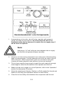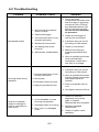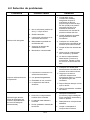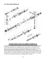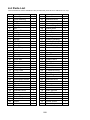
1
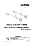
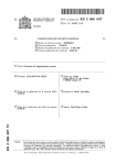
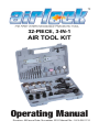
32-PIECE, 3-IN-1
AIR TOOL KIT
Operating Manual
Revision: AB Issue Date: November 2010 Manual No.: 0-LX-0261110
We Appreciate Your Business.
Thank you and congratulations on choosing Smarter Tools. Now you can stop
working harder and start working smarter.
This Operating Manual has been designed to instruct you on the correct use and
operation of your Smarter Tools’ product. Your satisfaction with this product and
its safe operation is our ultimate concern. Therefore please take the time to read
the entire manual, especially the Safety Precautions. They will help you to avoid
potential hazards that may exist when working with this product.
WARNING!
READ AND UNDERSTAND ALL SAFETY PRECAUTIONS
IN THIS MANUAL BEFORE OPERATING. FAILURE TO
COMPLY WITH INSTRUCTIONS IN THIS MANUAL
COULD RESULT IN PERSONAL INJURY, PROPERTY
DAMAGE, AND/ OR VOIDING OF YOUR WARRANTY.
SMARTER TOOLS WILL NOT BE LIABLE FOR ANY
DAMAGE BECAUSE OF FAILURE TO FOLLOW THESE
INSTRUCTIONS.
Operating Manual Number 0-LX-0261110
Airlock LX-026
32PC 3-IN-1 Air Tool Kit
Part No. LX-026
Published by:
Smarter Tools, Inc.
12195 Harley Club Drive
Ashland, VA 23005
888.241.8498
www.usesmartertools.com
MADE IN CHINA
Copyright © 2010 by
Smarter Tools, Inc.
Reproductions of this work, in whole or in part, without written permission of
the publisher are strictly prohibited.
The publisher does not assume and herby disclaims any liability to any party
for any loss or damage caused by any error or omission in this Manual,
whether such error results from negligence, accident, or any other cause.
Publication Date: 11.01.10
Table of Contents
SECTION 1: SAFETY INSTRUCTIONS AND WARNINGS .......................... 1-1
1.1 Symbol Usage ......................................................................................... 1-1
1.2 General Safety Rules .............................................................................. 1-2
1.3 Specific Safety Rules............................................................................... 1-4
1.4 Cautionary Labels ................................................................................... 1-5
SECCIÓN 1: INSTRUCCIONES DE SEGURIDAD Y ADVERTENCIAS ...... 1-6
1.1 Símbolo de uso ....................................................................................... 1-6
1.2 Normas Generales De Seguridad ........................................................... 1-7
1.3 Normas Específicas De Seguridad .......................................................... 1-10
1.4 Etiquetas De Precaución ......................................................................... 1-11
SECTION 2: INITIAL TOOL SET UP/ASSEMBLY ....................................... 2-1
2.1 Specifications .......................................................................................... 2-1
2. 2 Set Up/Assembly .................................................................................... 2-2
2.3 Tool Set Up ............................................................................................. 2-2
2.4 Connecting to Air Supply ......................................................................... 2-3
SECCIÓN 2: HERRAMIENTA DE AJUSTE INICIAL / ASAMBLEA ............ 2-6
2.1 Especificaciones ...................................................................................... 2-6
2.2 Configuración/Asamblea ......................................................................... 2-7
2.3 Herramienta de Configuración................................................................. 2-7
2.4 Conexión a Aire Suministro ..................................................................... 2-8
SECTION 3: OPERATION ............................................................................ 3-1
3.1 Tool Body ................................................................................................ 3-1
3.2 Air Ratchet............................................................................................... 3-1
3.3 Air Drill ..................................................................................................... 3-2
3.4 Air Die-Grinder ........................................................................................ 3-3
SECCIÓN 3: OPERACIÓN ........................................................................... 3-4
3.1 Cuerpo de la herramienta ........................................................................ 3-4
3.2 Aire Trinquete ......................................................................................... 3-4
3.3 Aire Taladro ............................................................................................. 3-5
3.4 Air Muere Amoladora............................................................................... 3-6
SECTION 4: MAINTENANCE AND TROUBLESHOOTING ........................ 4-1
4.1 User Maintenance ................................................................................... 4-1
4.2 Troubleshooting ....................................................................................... 4-2
SECCIÓN 4: MANTENIMIENTO Y RESOLUCIÓN DE PROBLEMAS ........ 4-3
4.1 Mantenimiento por el usuario .................................................................. 4-3
4.2 Solución de problemas ............................................................................ 4-4
4.3 Assembly Diagram .................................................................................. 4-5
4.4 Parts List ................................................................................................. 4-6
SECTION 1:
SAFETY INSTRUCTIONS AND WARNINGS
1.1 Symbol Usage
This manual contains important information that you need to know and
understand in order to assure YOUR SAFETY and PROPER OPERATION
OF EQUIPMENT. The following symbols help you recognize this information.
Please read the manual and pay attention to these sections.
Save These Important Safety Instructions!
Read and understand all of these safety instructions. Be sure to
retain them for future use.
WARNING!
WARNINGS INDICATE A CERTAINTY OR STRONG
POSSIBILITY OF PERSONAL INJURY OR DEATH IF
INSTRUCTIONS ARE NOT FOLLOWED.
CAUTION:
CAUTIONS INDICATE A POSSIBILITY OF EQUIPMENT
DAMAGE IF INSTRUCTIONS ARE NOT FOLLOWED
PROPERLY.
Note:
Notes give helpful information
Improper operation of pneumatic tools can cause serious injury or death, or
damage to other equipment or property, if the operator does not strictly observe
all safety rules and take precautionary actions.
Keep this manual in a safe and dry place for future reference of the safety
warnings and precautions, assembly, operating, inspection, maintenance and
cleaning procedures.
1-1
WARNING!
SOME DUST CREATED BY POWER SANDING, SAWING,
GRINDING AND OTHER CONSTRUCTION ACTIVITIES
CONTAINS CHEMICALS KNOWN TO CAUSE CANCER,
BIRTH DEFECTS, OR OTHER REPRODUCTIVE HARM.
Some examples of these chemicals are:
Lead from lead-based paints
Crystalline silica form bricks, cement and other masonry products
Arsenic and chromium from chemically treated lumber
Your risk from exposure varies, depending on how often you do this type of work.
To reduce your exposure to these chemicals: work in a wellventilated area, and use approved personal protective equipment
such as dust masks that are specially designed to filter out
microscopic particles (California Health & Safety Code 25249.5,
et seq.).
1.2 GENERAL SAFETY RULES
Read and understand all instructions.
Failure to follow all instructions listed in the following pages may result in electric
shock, fire, and/or serious injury.
Work Area
1.
Keep your work area clean and well lit. Cluttered benches and dark
areas invite accidents.
2.
Do not operate pneumatic tools in explosive atmospheres, such as in
the presence of flammable liquids, gases, or dust. Pneumatic tools
create sparks which may ignite flammables.
3.
Keep bystanders, children and pets away while operating a pneumatic
tool. Distractions can cause you to lose control. Protect others in the
work area from debris such as metal filings and sparks. Provide barriers
or shields as needed.
Personal Safety
1.
Stay alert. Watch what you are doing, and use common sense when
operating a pneumatic tool. Do not use a pneumatic tool while tired or
under the influence of drugs, alcohol, or medication. A moment of
inattention while operating pneumatic tools may result in serious
personal injury.
1-2
2.
3.
Dress properly. Do not wear loose clothing or jewelry. Contain long hair.
Keep your hair, clothing, and gloves away from moving parts. Loose
clothes, jewelry, or long hair can be caught in moving parts.
Avoid accidental starting. Be sure the trigger is off before connecting to
the air supply. Carrying pneumatic tools with your finger on the trigger,
or connecting pneumatic tools to the air supply with the trigger on,
invites accidents.
4.
Remove adjusting keys or wrenches before turning on the tool. A
wrench or a key that is left attached to a rotating part of the tool may
result in personal injury.
5.
Do not overreach. Keep proper footing and balance at all times. Proper
footing and balance enables better control of the tool in unexpected
situations.
6.
Use safety equipment. Always wear ANSI-approved safety glasses
underneath a full face shield, and hearing protection.
WARNING!
THE OPERATION OF ANY TOOL CAN RESULT IN FOREIGN
OBJECTS BEING THROWN INTO YOUR EYES, WHICH CAN
RESULT IN SEVERE EYE DAMAGE. BEFORE BEGINNING
OPERATION, ALWAYS WEAR SAFETY GOGGLES OR
SAFETY GLASSES WITH SIDE SHIELDS AND A FULL FACE
SHIELD WHEN NEEDED.
We recommend wide vision safety mask for use over eyeglasses
or standard safety glasses with side shields. Always wear eye
protection which is marked to comply with ANSI Z87.1.
Use and Care
1.
Use clamps or other practical ways to secure and support the work
piece to a stable platform. Holding the work by hand is unstable and
may lead to loss of control. Only work on a work-piece that is properly
secured.
2.
Do not force the tool. Use the correct tool for your application. The
correct tool will do the job better and safer at the rate for which it is
designed.
3.
Do not use the power tool if the trigger does not turn it on or off. Any tool
that cannot be controlled with the trigger is dangerous and must be
replaced.
4.
Disconnect the air hose from the tool before making any adjustments,
changing accessories, or storing the tool. Such preventive safety
measures reduce the risk of starting the tool accidentally.
1-3
5.
Store idle tools out of reach of children and other untrained persons.
Tools are dangerous in the hands of untrained users.
6.
Maintain tools with care. Do not use a damaged tool. Tag damaged
tools "Do not use" until repaired.
7.
Check for misalignment or binding of moving parts, breakages of parts,
damaged air hose (not included), and any other condition that may
affect the tool's operation. If damaged, have the tool serviced before
using. Many accidents are caused by poorly maintained tools.
8.
Use only accessories that are recommended by the manufacturer for
your model. Accessories that may be suitable for one tool may become
hazardous when used on another tool.
9.
Guard against electric shock. Prevent body contact with grounded
surfaces such as pipes, radiators, ranges, and refrigerator enclosures.
WARNING!
RISK OF ELECTRICAL SHOCK.
THIS TOOL IS NOT PROVIDED WITH AN INSULATED
GRIPPING SURFACE.
Service
1.
Tool service must be performed only by qualified repair personnel.
Service or maintenance performed by unqualified personnel could result
in a risk of injury.
2.
When servicing a tool, use only identical replacement parts. Follow
instructions in the "Inspection, Maintenance and Cleaning" section of
this manual. Use of unauthorized parts or failure to follow maintenance
instructions may create a risk of injury.
1.3 SPECIFIC SAFETY RULES
1.
To avoid accidental injury, always wear ANSI-approved safety glasses,
a full face shield, and ear protection when operating pneumatic tools.
2.
Use clean, dry, regulated compressed air at 90 PSI. Do not exceed the
recommended 90 PSI. Never use oxygen, carbon dioxide, combustible
gases, or any other bottled gas as a power source for this tool.
3.
When connecting to the air supply: Prior to each use, if an automatic
oiler is not used, add two drops of air tool oil (not included) into the air
inlet fitting of the tool body.
4.
Always disconnect the tool body from its compressed air supply source,
and squeeze the trigger to release all compressed air in the tool before
performing any maintenance or service.
1-4
5.
The warnings, precautions, and instructions discussed in this manual
cannot cover all possible conditions and situations that may occur. The
operator must understand that common sense and caution are factors
which cannot be built into this product, but must be supplied by the
operator.
6.
Do not point air tool at people or animals.
7.
Hold air tool with both hands during use.
Vibration Hazard
This tool vibrates during use. Repeated or long-term exposure to vibration may
cause temporary or permanent physical injury, particularly to the hands, arms
and shoulders. To reduce the risk of vibration-related injury:
1.
Anyone using vibrating tools regularly or for an extended period should
first be examined by a doctor and then have regular medical check-ups
to ensure medical problems are not being caused or worsened from
use. Pregnant women or people who have impaired blood circulation to
the hand, past hand injuries, nervous system disorders, diabetes, or
Raynaud’s Disease should not use this tool. If you feel any medical or
physical symptoms related to vibration (such as tingling, numbness, and
white or blue fingers), seek medical advice as soon as possible.
2.
Do not smoke during use. Nicotine reduces the blood supply to the
hands and fingers, increasing the risk of vibration-related injury.
3.
Wear suitable gloves to reduce the vibration effects on the user.
4.
Use tools with the lowest vibration when there is a choice between different processes.
5.
Include vibration-free periods each day of work.
6.
Grip tool as lightly as possible (while still keeping safe control of it). Let
the tool do the work.
7.
To reduce vibration, maintain the tool as explained in this manual. If any
abnormal vibration occurs, stop use immediately.
1.4 CAUTIONARY LABELS
Found on the tool and packaging. Do not attempt to remove, destroy, or cover
labels. If labels become illegible, please contact Smarter Tools or a Smarter
Tools Authorized Service Center to order replacements.
1-5
SECCIÓN 1:
INSTRUCCIONES DE SEGURIDAD Y ADVERTENCIAS
1.1 Símbolo de uso
Este manual contiene información importante que necesita conocer y
comprender a fin de garantizar su seguridad y funcionamiento adecuado del
equipo. Los símbolos siguientes le ayudarán a reconocer esta información.
Por favor, lea el manual y prestar atención a estas secciones.
Guarde estas instrucciones de seguridad
importantes!
Lea y entienda todas las instrucciones de seguridad. Asegúrese de
mantenerlas para su uso futuro.
ADVERTENCIA!
LAS ADVERTENCIAS INDICAN UNA GRAN POSIBILIDAD
DE CERTEZA O DE LESIONES PERSONALES O LA
MUERTE SI NO SIGUE LAS INSTRUCCIONES.
PRECAUCIÓN:
PRECAUCIONES INDICAN UNA POSIBILIDAD DE DAÑOS
AL EQUIPO SI LAS INSTRUCCIONES NO SE SIGUEN
CORRECTAMENTE.
Nota:
Toma nota de dar información útil
El uso inadecuado de herramientas neumáticas pueden causar lesiones graves
o la muerte, o daños a otros equipos o la propiedad, si el operador no tiene que
observar estrictamente las normas de seguridad y tomar medidas de precaución.
Guarde este manual en un lugar seco y seguro para referencia futura de las
advertencias y precauciones de seguridad, montaje, operación, inspección,
mantenimiento y procedimientos de limpieza.
1-6
ADVERTENCIA!
ALGUNOS POLVOS CREADOS POR EL LIJADO,
ASERRADO, ESMERILADO Y OTRAS ACTIVIDADES
CONSTRUCTIVAS CONTIENE PRODUCTOS QUÍMICOS
QUE PRODUCEN CÁNCER, DEFECTOS DE NACIMIENTO U
OTROS DAÑOS REPRODUCTIVOS.
Algunos ejemplos de estos productos químicos son:
El plomo de pinturas a base de plomo
Ladrillos de sílice cristalina forma, el cemento y otros productos de
albañilería
Arsénico y cromo de madera tratada químicamente
El riesgo de exposición varía, dependiendo de cuantas veces se hace este tipo
de trabajo.
Para reducir la exposición a estas sustancias químicas: (. Salud
de California y el Código de Seguridad 25249.5 y siguientes)
trabajan en un área bien ventilada, y utilice equipo aprobado para
protección personal, tales como máscaras contra el polvo que
están especialmente diseñadas para filtrar partículas
microscópicas.
1.2 NORMAS GENERALES DE SEGURIDAD
Lea y entienda todas las instrucciones.
Si no se siguen todas las instrucciones que figuran en las páginas siguientes
puede causar descargas eléctricas, incendios y / o lesiones graves.
Área de trabajo
1.
Mantenga su área de trabajo limpia y bien iluminada. bancos de trabajo
desordenados y las zonas oscuras pueden provocar accidentes.
2.
No utilice las herramientas neumáticas en atmósferas explosivas, como
en presencia de líquidos inflamables, gases o polvos. Las herramientas
neumáticas generan chispas que pueden encender materiales
inflamables.
3.
Mantenga a los espectadores, niños y mascotas alejados cuando utilice
una herramienta neumática. Las distracciones pueden hacerle perder el
control. Proteja a los demas en el área de trabajo de los escombros,
como limaduras de metal y chispas. Barreras y escudos según sea
necesario.
Seguridad personal
1.
Manténgase alerta. Mire lo que está haciendo y use el sentido común
cuando utilice una herramienta neumática. No utilice una herramienta
1-7
neumática si está cansado o bajo la influencia de drogas, alcohol o
medicamentos. Un momento de distracción al utilizar herramientas
neumáticas se pueden producir lesiones personales graves.
2.
Vístase de manera adecuada. No use ropa suelta o joyas. El cabello
largo. Mantenga su cabello, la ropa y los guantes alejados de las piezas
móviles. La ropa suelta, joyas o el cabello largo pueden quedar
atrapados en las piezas móviles.
3.
Evite el encendido accidental. Asegúrese de que el gatillo antes de
conectar al suministro de aire. El transporte de herramientas
neumáticas con el dedo en el gatillo, o conectar herramientas
neumáticas para el suministro de aire con el gatillo, puede provocar
accidentes.
4.
Retire las llaves de ajuste antes de encender la herramienta. Una
herramienta o una llave que se deja en una pieza giratoria de la
herramienta puede resultar en lesiones personales.
5.
No se estire demasiado. Mantenga la postura y el equilibrio en todo
momento. Un buen apoyo y equilibrio permiten un mejor control de la
herramienta en situaciones inesperadas.
6.
Use equipo de seguridad. Siempre use anteojos de seguridad
aprobados por ANSI debajo de una máscara facial completa, y
protección para los oídos.
ADVERTENCIA!
LA UTILIZACIÓN DE CUALQUIER HERRAMIENTA PUEDE
RESULTAR EN OBJETOS EXTRAÑOS EN LOS OJOS, QUE
PUEDE RESULTAR EN GRAVES DAÑOS OCULARES.
ANTES DE COMENZAR LA OPERACIÓN, SIEMPRE GAFAS
DE SEGURIDAD O GAFAS DE SEGURIDAD CON
PROTECCIONES LATERALES Y UNA CARETA COMPLETA
CUANDO SEA NECESARIO.
Le recomendamos que oculten amplias de seguridad visión
encima de los anteojos o gafas de seguridad con protección
lateral. Siempre use protección ocular con la marca de
cumplimiento con la norma ANSI Z87.1.
Uso y cuidado
1.
Utilice abrazaderas u otro método práctico para asegurar y sostener la
pieza de trabajo en una plataforma estable. Sostener el trabajo a mano
es inestable y puede conducir a la pérdida de control. Sólo si se trabaja
en una pieza de trabajo que se encuentra segura.
1-8
2.
No fuerce la herramienta. Utilice la herramienta correcta para su
aplicación. La herramienta correcta hará el trabajo mejor y más seguro
a la velocidad para la cual fue diseñada.
3.
No utilice la herramienta eléctrica si el gatillo no la enciende o apaga.
Cualquier herramienta que no puede ser controlada con el gatillo es
peligrosa y debe ser reemplazado.
4.
Desconecte la manguera de aire de la herramienta antes de hacer
cualquier ajuste, cambiar accesorios o guardar la herramienta. Estas
medidas de seguridad preventivas reducen el riesgo de arrancar la
herramienta accidentalmente.
5.
Guarde las herramientas fuera del alcance de los niños y otras
personas no capacitadas. Las herramientas son peligrosas en manos
de personas inexpertas.
6.
Mantenga las herramientas con cuidado. No utilice una herramienta
dañada. Colóquele una etiqueta que diga "No use" hasta que sea
reparada.
7.
Verifique la alineación de las piezas móviles, rotura de piezas, la
manguera de aire dañado (no incluido), y cualquier otra condición que
pueda afectar el funcionamiento de la herramienta. Si está dañada, la
herramienta antes de usarla. Muchos accidentes son causados por
herramientas mal mantenidas.
8.
Utilice solamente los accesorios recomendados por el fabricante para
su modelo. Los accesorios que pueden ser adecuados para una
herramienta pueden resultar peligrosos si se utilizan en otra.
9.
Protegerse contra descargas eléctricas. Evite el contacto corporal con
superficies aterrizadas tales como tuberías, radiadores, estufas y
refrigeradores.
ADVERTENCIA!
RIESGO DE DESCARGA ELÉCTRICA.
ESTA HERRAMIENTA NO ESTÁ PROVISTO DE UNA
SUPERFICIE AISLADA DEL MANGO.
Servicio
1.
Servicio de mantenimiento debe ser realizado únicamente por personal
calificado. Servicio o mantenimiento realizado por personal no calificado
puede resultar en un riesgo de lesión.
2.
Al reparar una herramienta, utilice únicamente piezas de repuesto
idénticas. Siga las instrucciones de la "Inspección, Mantenimiento y
Limpieza" de este manual. El uso de piezas no autorizadas o no seguir
las instrucciones de mantenimiento puede crear un riesgo de lesión.
1-9
1.3 NORMAS ESPECÍFICAS DE SEGURIDAD
1.
Para evitar accidentes, use siempre anteojos de seguridad aprobados
por ANSI, una máscara facial completa, y protección para los oídos
cuando trabaje con herramientas neumáticas.
2.
Utilice aire limpio y seco, y regulado a 90 PSI. No exceda la 90 PSI.
Nunca use oxígeno, dióxido de carbono, gases combustibles, o
cualquier otro gas embotellado como fuente de energía para esta
herramienta.
3.
Cuando se conecta al suministro de aire: Antes de cada uso, si un
engrasador automático no se utiliza, agregue dos gotas de aceite para
herramientas neumáticas (no incluidas) en el conector de entrada de
aire del cuerpo de la herramienta.
4.
Desconecte siempre el cuerpo de la herramienta de su fuente de
suministro de aire comprimido, y apretar el gatillo para liberar todo el
aire comprimido en la herramienta antes de realizar cualquier
mantenimiento o servicio.
5.
Las advertencias, precauciones y consejos de este manual no puede
cubrir todas las condiciones y situaciones que puedan ocurrir. El
operador debe entender que el sentido común y la prudencia son
factores que no se puede construir en este producto, sino que debe ser
suministrado por el operador.
6.
No herramienta neumática punto en personas o animales.
7.
Sujete la herramienta de aire con ambas manos durante su uso.
Vibración de peligro
Esta herramienta vibra durante el uso. La exposición repetida o largo plazo
de vibración ¬ puede causar lesiones físicas temporales o permanentes,
sobre todo en las manos, los brazos y los hombros. Para reducir el riesgo
de lesiones relacionadas con las vibraciones:
1.
Cualquier persona que usa herramientas que vibran con regularidad o
durante un período prolongado primero debe ser examinado por un
médico y someterse regularmente a exámenes médicos para
asegurarse de problemas médicos no están siendo causada o
agravada por el uso. Las mujeres embarazadas o las personas que
tienen impedimentos circulación de la sangre a la mano, lesiones
pasado la mano, trastornos del sistema nervioso, diabetes, o
enfermedad de Raynaud no debe usar esta herramienta. Si usted
siente algún síntoma médicos o físicos relacionados con las vibraciones
(como hormigueo, entumecimiento, y los dedos de color blanco o azul),
acuda al médico tan pronto como sea posible.
2.
No fume durante el uso. La nicotina reduce el suministro de sangre a
las manos y los dedos, aumentando el riesgo de lesiones relacionadas
con las vibraciones.
1-10
3.
Use guantes apropiados para reducir los efectos de vibración en el
usuario.
4.
Use herramientas con la vibración más baja cuando hay una elección
entre los procesos de dife-rentes.
5.
Incluir sin vibraciones períodos cada día de trabajo.
6.
Agarre la herramienta lo más ligero posible (sin dejar de mantener un
control seguro de la misma). Deje que la herramienta haga el trabajo.
7.
Para reducir la vibración, mantenimiento de la herramienta como se
explica en este manual. Si cualquier vibración anormal, deje de usarlo
inmediatamente.
1.4 ETIQUETAS DE PRECAUCIÓN
Que se encuentran en la herramienta y el embalaje. No trate de remover,
destruir, o cubrir las etiquetas. Si las etiquetas se vuelven ilegibles, póngase en
contacto con Smarter Tools o un Smarter Tools centro de servicio autorizado
para ordenar reemplazos.
1-11
SECTION 2:
INITIAL TOOL SET UP/ASSEMBLY
2.1 Specifications
Maximum Air Pressure
90 PSI
Air Inlet
1/4” – 1/8” NPT Female
Average Air Consumption
AIR RATCHET
Maximum RPM
150 RPM
Maximum Torque
60ft/lb
Maximum Capacity
5/8”
Chuck
1/2”
Settings
Forward/Reverse
AIR DRILL
Maximum RPM
2200 RPM
Chuck
1/10mm, 3/8”, 24 UNF
Reversible
No
AIR DIE GRINDER
Maximum RPM
Collet
20000 RPM
1/4”
ACCESSORIES
Sanding Wheels (4)
Aluminum Oxide; 100 Grit
Sizes: 13/16”, 1”, 1-3/16”, 1-9/16”
Grinding Stones (5)
Ball – 13/16”
Wheel – 1/2”
Cone – 1-7/16”
Tree – 1”
Tree – 15/16”
Drill Bits (10)
High Speed Steel
Sizes: 1/16”, 5/64”, 3/32”, 7/64”, 1/8”, 9/64”,
5/32”, 11/64”, 3/16”, 1/4”
Sockets (4)
Sizes: 9/16”, 5/8”, 11/16”, 3/4”
Wrenches
11 Gauge Sheet Steel
3/4” and 9/16” openings
Maximum speeds are stated at maximum air pressure. Excess air pressure is
hazardous and may cause the tool to exceed stated maximum speeds.
2-1
2.2 Set Up/Assembly
CAUTION:
READ THE ENTIRE IMPORTANT SAFETY INFORMATION
SECTION AT THE BEGINNING OF THIS MANUAL
INCLUDING ALL TEXT UNDER SUBHEADINGS THEREIN
BEFORE SET UP/ASSEMBLY OR USE OF THIS PRODUCT.
Note:
For additional information regarding the location of parts listed
in the following pages, refer to the Assembly Diagram near the
end of this manual.
When unpacking, make sure that all items are intact and undamaged. DO NOT
ATTEMPT TO OPERATE THIS TOOL WITH DAMAGED COMPONENTS.
Note:
This air tool ships with a protective plug covering the air inlet.
This plug MUST be removed to operate. DO NOT attempt
assembly without removing the protective plug first.
2.3 Tool Set Up
1.
Before attaching the air tool to the air supply source, select the
attachment (Grinder, Ratchet, or Drill) needed for the job.
Attachment release ring
Pin and notch
2.
To fasten the attachment to the tool body, grip attachment release ring,
turn it to align pin and notch (only when the pin aligns with the notch can
attachments be inserted or removed), and pull back towards trigger.
2-2
3.
Align hex drive in body to hex drive of attachment. Slide end of
attachment into body and release attachment release ring.
4.
To lock the attachment in place, turn the attachment release ring so that
the pin is no longer aligned with the pin.
CAUTION:
THERE IS A RISK OF THE ATTACHMENT BEING
ACCIDENTALLY RELEASED DURING OPERATION IF THE
ATTACHMENT RELEASE RING IS NOT TURNED SO THAT
THE NOTCH AND PIN ARE NO LONGER ALIGNED.
5.
To remove attachments, turn the attachment release ring to realign the
notch and pin and pull back on the ring towards the trigger. Once the
attachment is released, remove the attachment from the tool body.
6.
Unused attachments should be kept in the provided case to keep them
clean and protected.
2.4 Connecting to Air Supply
WARNING!
TO PREVENT EXPLOSION: USE ONLY CLEAN, DRY,
REGULATED, COMPRESSED AIR TO POWER THIS TOOL.
DO NOT USE OXYGEN, CARBON, DIOXIDE,
COMBUSTIBLE GASES, OR ANY OTHER BOTTLED GAS
AS A POWER SOURCE FOR THIS TOOL.
Note:
If an automatic oiler system is not used, add a few drops of
pneumatic/air too oil to the air line connection before operation.
Add a few more drops after each hour of use.
CAUTION:
IF YOU ARE WORKING WITH AN AIR HOSE THAT IS NOT
“SELF-COILING”, ROUTE THE AIR HOSE ALONG A SAFE
ROUTE TO REACH THE WORK AREA WITHOUT
CREATING A TRIPPING HAZARD OR EXPOSING IT TO
POSSIBLE DAMAGE.
2-3
1.
Incorporate an in-line oiler, shut off valve, regulator with pressure
gauge, and filter for best service. An in-line shut-off valve is an
important safety device because it controls the air supply even if
the air hose is ruptured.
Note:
Attaching a 1/4” self coiling air hose between the air supply
and the tool will greatly increase versatility.
2.
Attach an air hose to the compressor’s air outlet (use of thread sealing
tape is recommended). Connect opposite end of the air hose to the air
inlet of the tool. Other components, such as a connector and quick
coupler will make operation more efficient, but are not required.
3.
The air hose must be long enough to reach the work area with enough
extra length to allow free movement of the operator and the tool.
4.
Make sure the tool’s trigger is in the off position; refer to the “Operation”
section for description of controls.
5.
Select the attachment (Grinder, Ratchet, or Drill) needed for the job and
fasten to tool body (see Operation section for instructions).
6.
Close the in-line safety valve between the compressor and the tool.
2-4
7.
Turn on the air compressor according to the manufacturer’s directions
and allow it to build up pressure until it cycles off.
8.
Adjust the air compressor’s output regulator so that the air output is
enough to properly power the tool, but the output shall not exceed the
tool’s maximum air pressure (90 PSI) at any time. Adjust the pressure
gradually, while checking the air output gauge to set the appropriate
pressure range.
9.
Inspect the air connections for leaks. Repair any leaks found.
10. When the tool is not in use, detach it from the air supply and discharge
any residual air pressure with the trigger before setting the tool down.
Note:
Residual air pressure should not be present after the tool is
disconnected from the air supply. However it is a good safety
measure to attempt to discharge the tool in a safe fashion to
ensure that the tool is disconnected and unpowered.
Note:
Air flow, and therefore tool performance, can be hindered by
undersized air supply components.
2-5
SECCIÓN 2:
HERRAMIENTA DE AJUSTE INICIAL / ASAMBLEA
2.1 Especificaciones
Máxima presión de aire
90 PSI
Entrada de aire
1/4” – 1/8” NPT Female
Promedio de consumo de aire
AIRE TRINQUETE
Maximum RPM
150 RPM
De par máximo
60ft/lb
Capacidad máxima
5/8”
Chuck
1/2”
Configuración
Avance / Retroceso
AIRE TALADRO
Maximum RPM
2200 RPM
Chuck
1/10mm, 3/8”, 24 UNF
Reversibles
No
AIRE MUERE AMOLADORA
Maximum RPM
Cuello
20000 RPM
1/4”
ACCESORIOS
Lijado Ruedas (4)
El óxido de aluminio; 100 Arena
Tamaños: 13/16”, 1”, 1-3/16”, 1-9/16”
Piedras de amolar (5)
Bola – 13/16”
Rueda – 1/2”
Cono – 1-7/16”
Árbol – 1”
Árbol – 15/16”
Brocas (10)
Acero de alta velocidad
Tamaños: 1/16”, 5/64”, 3/32”, 7/64”, 1/8”,
9/64”, 5/32”, 11/64”, 3/16”, 1/4”
Sockets (4)
Tamaños: 9/16”, 5/8”, 11/16”, 3/4”
Llaves
11 Medidor de hoja de acero
3/4” y 9/16” aberturas
Las velocidades máximas se presentan a la presión máxima del aire. El exceso
de presión de aire es peligroso y puede causar la herramienta para superar las
velocidades máximas declaró.
2-6
2.2 Configuración / Asamblea
PRECAUCIÓN:
LEA TODO EL ARTICULO IMPORTANTE INFORMACIÓN DE
SEGURIDAD EN EL COMIENZO DE ESTE MANUAL DE
TODOS INCLUYENDO TEXTO en las su partidas MISMO
ANTES DE AJUSTE / ASAMBLEA O USO DE ESTE
PRODUCTO.
Nota:
Para obtener información adicional sobre la ubicación de las
piezas que figuran en las páginas siguientes, se refieren al
esquema de montaje cerca de la final de este manual.
Al desembalar, asegúrese de que todos los artículos están intactos y en buen
estado. NO TRATE DE UTILIZAR ESTA HERRAMIENTA CON PIEZAS
DAÑADAS.
Nota:
Esta herramienta de buques de aire con un tapón de
protección que cubre la entrada de aire. Este enchufe debe
ser removido para operar. NO TRATE de montaje sin quitar el
tapón de protección en primer lugar.
2.3 Herramienta de Configuración
1.
Antes de conectar el aparato de aire a la fuente de suministro de aire,
seleccione el archivo adjunto (Amoladora, Trinquete, o Taladro)
necesarios para el trabajo.
Attachment release ring
Pin and notch
2.
Para fijar el apego al cuerpo de la herramienta, el apego agarre anillo
de liberación, que a su vez para alinear los pines y la muesca (sólo
2-7
cuando el perno se alinea con la muesca puede adjuntos introducir o
sacar), y tire hacia gatillo.
3.
Alinee la unidad hexagonal en el cuerpo a la hexagonal de unidad de
archivo adjunto. Deslice el extremo de fijación en el anillo del cuerpo y
la liberación de la liberación de fijación.
4.
Para bloquear el accesorio en su lugar, gire el anillo de liberación
apego manera que el orificio ya no se alinea con el perno.
PRECAUCIÓN:
HAY UN RIESGO DE EMBARGO SE accidentalmente
DURANTE EL FUNCIONAMIENTO SI EL ANILLO DE
LIBERACIÓN DE EMBARGO NO SE DA VUELTA PARA
QUE LA MUESCA Y PIN ya no están alineados.
5.
Para quitar los archivos adjuntos, a su vez el anillo de liberación apego
a realinear la muesca y el pasador y tirar hacia atrás en el anillo hacia
el gatillo. Una vez que el archivo adjunto se libera, quitar el accesorio
del cuerpo de la herramienta.
6.
Accesorios no utilizados deberán mantenerse en el caso previsto para
mantenerlos limpios y protegidos.
2.4 Conexión a Aire Suministro
ADVERTENCIA!
PARA EVITAR LA EXPLOSIÓN: USO EXCLUSIVO DE
LIMPIEZA, seco y regulado, AIRE COMPRIMIDO PARA
PODER ESTA HERRAMIENTA. NO USO oxígeno, carbono,
DIÓXIDO DE, GASES COMBUSTIBLES, ni ningún gas
envasado OTROS COMO FUENTE DE ENERGÍA PARA
ESTA HERRAMIENTA.
Nota:
Si un sistema de engrasador automático no se utiliza, se
añaden unas gotas de neumático / del aire demasiado aceite a
la conexión de la línea aérea antes de la operación. Añadir
unas gotas más después de cada hora de uso.
PRECAUCIÓN:
SI NO SE ENCUENTRA TRABAJO CON UNA MANGUERA
DE AIRE QUE NO ES "AUTO-arrolla", pase la manguera de
aire a lo largo de una ruta segura para llegar al área
TRABAJO, sin por ello el riesgo de tropiezos ni la exponga a
posibles daños.
2-8
1.
Incorporar un engrasador en línea, la válvula de cierre, regulador con
manómetro y filtro para el mejor servicio. Una línea en la válvula de
cierre es un importante dispositivo de seguridad debido a que controla
el suministro de aire, incluso si la manguera de aire se rompe.
Nota:
Colocación de un 1/4 "para manguera de aire enrollado entre
el suministro de aire y la herramienta será de gran aumento
de la versatilidad.
2.
Conecte una manguera de aire a la salida de aire del compresor (el uso
de cinta de sellado de roscas se recomienda). Conecte el otro extremo
de la manguera de aire a la entrada de aire de la herramienta. Otros
componentes, tales como un acoplador de conexión rápida y se hace la
operación más eficiente, pero no son necesarios.
3.
La manguera de aire debe ser lo suficientemente largo para llegar a la
zona de trabajo con mayor longitud suficiente para permitir el
movimiento libre del operador y la herramienta.
4.
Haga gatillo que la herramienta se encuentra en la posición de
apagado, consulte la sección "Operación" para la descripción de los
controles.
2-9
5.
Seleccione el archivo adjunto (Amoladora, Trinquete, o Taladro)
necesarios para el trabajo y fijar el cuerpo de la herramienta (ver
sección de operación para las instrucciones).
6.
Cierre la válvula de seguridad en línea entre el compresor y la
herramienta.
7.
Encienda el compresor de aire de acuerdo a las instrucciones del
fabricante y deje que se acumule presión hasta que los ciclos de
apagado.
8.
Ajuste el regulador del compresor de aire de salida de modo que la
salida de aire es suficiente para poder correctamente la herramienta,
pero la salida no será superior a la presión de la herramienta de aire
máximo (90 PSI) en cualquier momento. Ajustar la presión poco a poco,
al comprobar el medidor de salida de aire para ajustar el rango de
presión adecuado.
9.
Inspeccione las conexiones de aire que no haya fugas. Repare las
fugas de agua.
10. Cuando la herramienta no esté en uso, desconéctela del suministro de
aire y descargar toda la presión de aire residual con el gatillo antes de
dejar la herramienta.
Nota:
La presión residual de aire no deben estar presentes cuando la
herramienta esté desconectada de la alimentación de aire. Sin
embargo, es una buena medida de seguridad para intentar la
descarga de la herramienta de una manera segura para
garantizar que la herramienta esté desconectada y sin motor.
Nota:
El flujo de aire, y por lo tanto rendimiento de la herramienta,
puede verse obstaculizado por talla inferior a los componentes
de suministro de aire.
2-10
SECTION 3:
OPERATION
3.1 Tool Body
1.
If an automatic oiler is not used, add a few drops of pneumatic/air tool
oil to the airline connection before use. Add a few more drops after each
hour of continual use.
2.
This air tool is equipped with a safety catch trigger that locks the trigger
into the off position when the trigger is not depressed.
3.
To operate trigger: push forward on the safety catch with your thumb
while pushing downward on the trigger.
4.
The rotation speed of the tool is controlled by the amount of pressure
applied to the trigger.
5.
DO NOT continue to operate the tool if the safety catch does not lock
the trigger in the off position when released.
6.
Always ensure that the trigger is in the locked (OFF) position when
changing attachments.
7.
Change attachments according to instructions in the “Tool Set Up”
section of this manual.
3.2 Air Ratchet
1.
The Ratchet attachment is designed to work with all 1/2” drive sockets.
Four are included in the case: 9/16”, 5/8”, 11/16”, and 3/4”
2.
Before installing a socket onto the Ratchet Anvil, make sure that the
tool’s trigger is in the locked (OFF) position.
3.
Slide socket onto anvil until it locks into place.
4.
Once socket is installed, set the Forward/Reverse knob to the desired
direction.
5.
Place the socket on the bolt or nut that needs to tightened/loosened.
6.
Hold the tool firmly with both hands, as torque will cause the tool to twist
when the trigger is depressed.
7.
Gently squeeze the trigger to tighten or loosen bolt/nut. Apply additional
pressure on trigger as needed.
8.
If the bolt/nut requires a higher level of torque than the tool can provide
at 90 PSI then an alternate tool should be used to achieve desired
torque. DO NOT attempt to raise air pressure to get more torque out of
the tool. Operating the tool at a higher than maximum rated pressure
can result in damage to the tool and/or accessory and possible injury to
the operator.
3-1
CAUTION:
TO PREVENT TOOL AND ACCESSORY FAILURE,
RESULTING IN INJURY: DO NOT EXCEED THE TOOL’S 90
PSI AIR PRESSURE RATING.
3.3 Air Drill
1.
The Drill attachment is designed to work with drill bits ranging from 1/16”
to 15/64”. Ten are included in the case: 1/16”, 5/64”, 3/32”, 7/64”, 1/8”,
9/64”, 5/32”, 11/64”, 3/16”, and 1/4”
2.
Before installing a bit into the chuck, make sure that the tool’s trigger is
in the locked (OFF) position.
3.
Slide selected bit into chuck. Use the chuck key (turning
counterclockwise) if the chuck needs to be opened more to
accommodate bit.
4.
Use the chuck key (turning clockwise) to secure bit firmly into chuck.
Ensure that the bit stays in a straight upright position. If the bit is
crooked and not upright it will not secure properly in chuck.
5.
DO NOT attempt to install a drill bit that exceeds the 3/8” chuck
capacity.
6.
Mark the area you wish to drill with a center punch (not included).
7.
Gently squeeze the trigger to tighten or loosen bolt/nut. Apply additional
pressure on trigger as needed.
8.
Drill only as deep as necessary. DO NOT drill into walls without first
verifying there are no hidden utility wires or hazards behind drilling
surface.
9.
When hole is drilled, remove drill bit from hole while the tool is still
spinning. This will prevent the bit from getting caught in the hole and
causing damage. If the bit does get caught immediately release trigger.
WARNING!
DO NOT TOUCH chuck or drill bit while the drill attachment is
still running.
WARNING!
DO NOT attempt to remove drill bit immediately after drilling.
Allow bit to cool before attempting to remove.
3-2
10. DO NOT lay the tool down until it has come to a complete stop. Moving
parts can grab the surface and pull the tool out of control.
3.4 Air Die-Grinder
1.
The Grinder attachment is designed to work with 1/4” grinder
accessories. Nine are included in the case: Four sanding wheels, 13/16”
O.D., 1” O.D., 1-3/16” O.D., and 1-9/16” O.D.; Five grinding stones, Ball
(13/16” O.D.), Wheel (1” O.D.), Cone (15/16” O.D.), Tree (9/16” O.D.),
and Tree (3/4” O.D.)
2.
Before installing an accessory into the collet, make sure that the tool’s
trigger is in the locked (OFF) position.
3.
Select the accessory appropriate to your needs. Use one wrench to hold
the collet holder and the other wrench to open the collet nut.
4.
Insert the shaft of the accessory into the open collet and use the
wrenches to tighten the collet nut.
5.
Gently squeeze the trigger to start grinding before you touch the work
surface.
6.
Allow the grinder to do the work. Apply additional pressure on trigger as
needed. DO NOT use excessive force against the surface you are
grinding. If you place too much pressure on the work-piece and the
grinder stalls, immediately release the trigger and pull the grinder away
from the work surface.
7.
If the tool requires more force to accomplish the task, verify that the tool
is receiving sufficient, unobstructed airflow (CFM) and the maximum air
pressure (90 PSI) is being provided.
8.
DO NOT attempt to raise air pressure to get more out of the tool.
Operating the tool at a higher than maximum rated pressure can result
in damage to the tool and/or accessory and possible injury to the
operator.
9.
If the tool still does not have sufficient force at maximum pressure and
airflow, then a larger tool may be required.
10. DO NOT lay the tool down until it has come to a complete stop. Moving
parts can grab the surface and pull the tool out of control.
3-3
SECCIÓN 3:
OPERACIÓN
3.1 Cuerpo de la herramienta
1.
Si un engrasador automático no se utiliza, se añaden unas gotas de
neumático / aceite para herramientas de aire a la conexión de las
aerolíneas antes de su uso. Añadir unas gotas más después de cada
hora de uso continuo.
2.
Esta herramienta de aire está equipado con un disparador de captura
de seguridad que bloquea el gatillo en la posición de apagado cuando
el gatillo no está presionado.
3.
Para operar el gatillo: impulsar en el seguro con el pulgar mientras se
empuja a la baja en el gatillo.
4.
La velocidad de rotación de la herramienta se controla por la cantidad
de presión ejercida sobre el gatillo.
5.
No mantener en funcionamiento la herramienta si el seguro no se
bloquea el gatillo en la posición inicial al soltarlos.
6.
Asegúrese siempre de que el gatillo se encuentra en la posición de
bloqueo (OFF) al cambiar accesorios.
7.
Cambie los accesorios de acuerdo a las instrucciones en el "conjunto
de herramientas hasta" de este manual.
3.2 Aire Trinquete
1.
El accesorio de Trinquete está diseñado para trabajar con todos los
01.02 tomas de unidad”. Cuatro están incluidos en el caso: 9/16 ", 5/8",
11/16 "y 3/4"
2.
Antes de instalar un enchufe en el yunque del trinquete, asegúrese de
que desencadenan la herramienta se encuentra en la posición de
bloqueo (OFF).
3.
Toma de diapositivas sobre el yunque hasta que encaje en su lugar.
4.
Una vez que toma sea instalado, establezca el avance / retroceso
mando en la dirección deseada.
5.
6.
Coloque el zócalo en el perno o la tuerca que hay que apretar / aflojar.
Sujete la herramienta firmemente con ambas manos, como par hará
que la herramienta se tuerza cuando se presiona el gatillo.
7.
Apriete suavemente el gatillo para apretar o aflojar el perno / tuerca.
Aplique una presión adicional en el gatillo cuando sea necesario.
8.
Si el perno / tuerca requiere un mayor nivel de esfuerzo de torsión de la
herramienta puede proporcionar a 90 PSI a continuación, una
herramienta alternativa se debe utilizar para lograr par deseado. NO
trate de aumentar la presión de aire para sacar más provecho del
3-4
esfuerzo de torsión de la herramienta. Operación de la herramienta en
una superior a la presión nominal máxima puede resultar en daños a la
herramienta y / o lesiones de accesorios y posibles para el operador.
PRECAUCIÓN:
PARA EVITAR LA HERRAMIENTA Y FALTA DE
ACCESORIOS, COMO RESULTADO DE LESIONES: NO
SUPERE LA HERRAMIENTA DE EVALUACIÓN 90 PSI
PRESION DE AIRE.
3.3 Aire Taladro
1.
El accesorio de taladro está diseñado para trabajar con brocas de 1/16
a 15/64 ". Diez están incluidos en el procedimiento: 1/16 ", 5/64", 3/32 ",
7/64", 1/8 ", 9/64", 5/32 ", 11/64", 3/16 ", y 1/4"
2.
Antes de instalar una broca en el mandril, asegúrese de que
desencadenan la herramienta se encuentra en la posición de bloqueo
(OFF).
3.
Diapositiva seleccionada poco en el mandril. Utilice la llave de la tirada
(girando hacia la izquierda) si la tirada es necesario abrir más para dar
cabida a poco.
4.
Utilice la llave de la tirada (girando en sentido horario) para asegurar
firmemente en poco tirada. Asegúrese de que la broca se queda en una
posición vertical recta. Si la broca está torcido y no vertical, no se
encuentra bien asegurado en el mandril.
5.
NO intente instalar una broca que exceda de 3/8 "capacidad de mandril.
6.
Marque el área que desea para perforar con un punzón (no incluido).
7.
Apriete suavemente el gatillo para apretar o aflojar el perno / tuerca.
Aplique una presión adicional en el gatillo cuando sea necesario.
8.
Sólo a la profundidad necesaria de perforación. NO perfore las paredes
sin antes verificar que no hay cables eléctricos ocultos o peligros detrás
de la superficie de perforación.
9.
Cuando el agujero se perfora, retire la broca del agujero, mientras que
la herramienta sigue girando. Esto evitará que la broca quede atrapado
en el agujero y los daños que causan. Si el bit es atrapado
inmediatamente soltar el gatillo.
ADVERTENCIA!
NO TOQUE MANDRIL O LA BROCA, MIENTRAS QUE EL
ACCESORIO DE TALADRO ESTÉ EN FUNCIONAMIENTO.
3-5
ADVERTENCIA!
NO INTENTE EXTRAER LA BROCA INMEDIATAMENTE
DESPUÉS DE LA PERFORACIÓN. DEJE QUE SE ENFRÍE
POCO ANTES DE INTENTAR QUITAR.
10. NO deje la herramienta hacia abajo hasta que ha llegado a una parada
completa. Las piezas móviles pueden engancharse en la superficie y
tirar de la herramienta fuera de control.
3.4 Air Muere Amoladora
1.
El accesorio de la amoladora está diseñada para trabajar con 1 / 4 accesorios
molino ". Nueve están incluidos en el procedimiento: Cuatro ruedas de lijado,
13/16 "de diámetro exterior, 1" de diámetro exterior, 1-3/16 "de diámetro
exterior, y 1-9/16" de diámetro exterior, cinco piedras de moler, Ball (13/16
"de diámetro exterior) , Rueda (1 "de diámetro exterior), Cono (15/16" de
diámetro exterior), Árbol (9/16 "de diámetro exterior), y el Árbol (3/4" OD)
2.
Antes de instalar un accesorio en la pinza, asegúrese de que desencadenan
la herramienta se encuentra en la posición de bloqueo (OFF)
3.
Seleccione el accesorio adecuado para sus necesidades. Con una llave para
sostener el titular de la pinza y la otra llave para abrir la tuerca de la boquilla.
4.
Inserte el eje del accesorio en la pinza abierta y el uso de las llaves para
apretar la tuerca de la boquilla.
5.
Apriete suavemente el disparador para comenzar a moler antes de tocar la
superficie de trabajo.
6.
Deje que el molino para hacer el trabajo. Aplique una presión adicional en el
gatillo cuando sea necesario. No use fuerza excesiva contra la superficie que
está pulido. Si usted pone demasiada presión en la pieza de trabajo y los
puestos de molino, suelte inmediatamente el gatillo y tire de la amoladora de
la superficie de trabajo.
7.
Si la herramienta requiere más fuerza para lograr la tarea, compruebe que la
herramienta está recibiendo suficiente flujo de aire sin obstrucciones (CFM) y
la presión máxima del aire (90 PSI) se está prestando.
8.
NO trate de aumentar la presión de aire para sacar más provecho de la
herramienta. Operación de la herramienta en una superior a la presión
nominal máxima puede resultar en daños a la herramienta y / o lesiones de
accesorios y posibles para el operador.
9.
Si la herramienta aún no tiene la suficiente fuerza a la máxima presión y flujo
de aire, a continuación, una herramienta más grande puede ser requerida.
10. NO deje la herramienta hacia abajo hasta que ha llegado a una parada
completa. Las piezas móviles pueden engancharse en la superficie y tirar de
la herramienta fuera de control.
3-6
SECTION 4:
MAINTENANCE AND TROUBLESHOOTING
4.1 User Maintenance
These procedures are in addition to the regular checks and maintenance
explained as part of the regular operation of the air-operated tool.
CAUTION:
PROCEDURES NOT SPECIFICALLY EXPLAINED IN THIS
MANUAL MUST BE PERFORMED ONLY BY A QUALIFIED
TECHNICIAN.
WARNING!
TO PREVENT SERIOUS INJURY FROM ACCIDENTAL
OPERATION: TURN OFF THE TOOL, DETACH THE AIR
SUPPLY, SAFELY DISCHARGE ANY RESIDUAL AIR
PRESSURE IN THE TOOL, AND MAKE SURE THE
TRIGGER IS IN THE OFF POSITION BEFORE
PERFORMING AND INSPECTION, MAINTENANCE, OR
CLEANING PROCEDURES.
WARNING!
TO PREVENT EXPLOSION: LUBRICATE THE TOOL ONLY
WITH SPECIFIED LUBRICANT. LUBRICATE THE AIR INLET
USING ONLY PNEUMATIC/AIR TOOL OIL. OTHER
LUBRICANTS MAY DAMAGE THE MECHANISM AND MAY
BE HIGHLY FLAMMABLE, CAUSING AN EXPLOSION.
1. Daily – Air Supply Maintenance:
Every day, perform maintenance on the air supply according to the
component manufacturers’ instructions. The lubricator’s oil level needs
to be maintained and the moisture filter must be regularly drained.
Performing routine maintenance on the air supply will allow the tool to
operate more safely and will also reduce wear on the tool.
2.
Quarterly – Tool Disassembly, Cleaning, and Inspection
Every 3 months, have the internal mechanism cleaned, inspected, and
lubricated by a qualified technician.
WARNING!
TO PREVENT SERIOUS INJURY FROM TOOL FAILURE: DO
NOT USE DAMAGED EQUIPMENT. IF ABNORMAL NOISE,
VIBRATION, OR AIR LEAK OCCURS, HAVE THE PROBLEM
CORRECTED BEFORE FURTHER USE.
4-1
4.2 Troubleshooting
Problem
Possible Cause
1. Not enough air pressure
and/or air flow.
2. Obstructed trigger.
Decreased Output
3. Incorrect lubrication or not
enough lubrication.
4. Blocked air inlet screen.
5. Air leaking from loose
housing.
6. Mechanism contaminated.
Solution
1. Check for loose
connections and make sure
that air supply is providing
enough air flow (CFM) at
the required pressure (90
PSI) to the tool’s air inlet.
Do not exceed maximum
air pressure.
2. Clean around trigger to
ensure free movement.
3. Lubricate using air tool oil
according to instructions.
4. Clean air inlet screen.
5. Make sure housing is
properly assembled and
tight.
6. Have a qualified technician
clean and lubricate
mechanism. Install an inline filter in air supply.
1. Lubricate using air tool oil
according to instructions.
1. Incorrect lubrication or not
enough lubrication.
Housing heats during
operation.
2. Worn parts.
3. Extended continuous use.
4. Applying excessive force.
2. Have a qualified technician
inspect internal mechanism
and replace parts as
needed.
3. Allow enough idle time to
cool.
4. Use lighter amount of force.
Severe air leakage
(slight air leakage is
normal, especially on
older tools)
1. Cross-threaded or loose
housing components.
2. Damaged valve or housing
3. Dirty, worn, or damaged
valve.
4-2
1. Check for incorrect
alignment and uneven
gaps. If needed,
disassemble and re-tighten.
2. Replace damaged
components.
3. Clean or replace valve
assembly.
SECCIÓN 4:
MANTENIMIENTO Y RESOLUCIÓN DE PROBLEMAS
4.1 Mantenimiento por el usuario
Estos procedimientos se suman a los controles y el mantenimiento explicarse
como parte de la operación regular de la herramienta neumática de
accionamiento.
PRECAUCIÓN:
LOS PROCEDIMIENTOS NO SE ESPECIFIQUE EN ESTE
MANUAL DEBE SER REALIZADO POR UN TECNICO
CALIFICADO.
ADVERTENCIA!
PARA EVITAR LESIONES GRAVES DE OPERACIÓN
ACCIDENTAL: APAGUE LA HERRAMIENTA, SEPARE EL
SUMINISTRO DE AIRE, CON SEGURIDAD DE DESCARGA
TODA LA PRESIÓN DE AIRE RESIDUAL EN LA
HERRAMIENTA Y HACER QUE EL GATILLO EN LA
POSICIÓN DE APAGADO ANTES DE INSPECCIÓN Y
MANTENIMIENTO, O LIMPIEZA.
ADVERTENCIA!
PARA EVITAR LA EXPLOSIÓN: LUBRICAR LA
HERRAMIENTA SOLO CON LUBRICANTE ESPECIFICADO.
LUBRICAR LA ENTRADA DE AIRE DE UTILIZAR SÓLO
NEUMÁTICOS / ACEITE DE AIRE DE LA HERRAMIENTA.
OTROS LUBRICANTES PUEDE DAÑAR EL MECANISMO Y
PUEDEN SER ALTAMENTE INFLAMABLES, CAUSANDO
UNA EXPLOSIÓN.
1.
Diario – Mantenimiento de aire de suministro:
Todos los días, realizar el mantenimiento en el suministro de aire de
acuerdo a las instrucciones de los fabricantes de componentes. El nivel de
lubricante de aceite tiene que ser mantenido y el filtro de humedad debe ser
drenada regularmente. Realizar el mantenimiento de rutina en el suministro
de aire permite que la herramienta funcione de forma más segura y también
se reducirá el desgaste de la herramienta.
2.
Trimestrales – Herramienta de desmontaje, Limpieza e Inspección
Cada 3 meses, el mecanismo interno limpiado, inspeccionado, y lubricado
por un técnico cualificado.
ADVERTENCIA!
PARA EVITAR LESIONES GRAVES POR FALTA DE
HERRAMIENTAS: NO USE EQUIPO DAÑADO. SI RUIDO
ANORMAL, VIBRACIÓN O AGUJERO DE AIRE OCURRE,
CORRIJA EL PROBLEMA ANTES DE UTILIZARLO.
4-3
4.2 Solución de problemas
Problema
Posible causa
1. No es suficiente presión de
aire y / o flujo de aire.
2. Gatillo obstruido.
3. Lubricación incorrecta o no
suficiente lubricación.
Disminución del gasto
4. Bloqueada la pantalla de
entrada de aire.
5. Aire que se escapa de
estabulación libre.
6. Mecanismo contaminado.
Solución
1. Compruebe si hay
conexiones sueltas y
asegúrese de que el
suministro de aire es
proporcionar suficiente flujo
de aire (CFM) a la presión
requerida (90 psi) a la
entrada de aire de la
herramienta. No exceda la
presión máxima del aire.
2. Limpie alrededor de gatillo
para garantizar la libre
circulación.
3. Lubrique con aceite para
herramientas neumáticas de
acuerdo a las instrucciones.
4. Limpie el filtro de entrada de
aire.
5. Hacer que la vivienda esté
bien montado y ajustado.
6. Un técnico especializado
debe limpiar y lubricar el
mecanismo. Instale un filtro
en línea en el suministro de
aire.
1. Lubrique con aceite para
herramientas neumáticas de
acuerdo a las instrucciones.
1. Lubricación incorrecta o no
suficiente lubricación.
Caja se calienta durante
la operación.
3. Extendido el uso continúo.
2. Haga que un técnico
calificado inspeccione
mecanismo interno y cambie
las piezas según sea
necesario.
4. La aplicación de fuerza
excesiva.
3. Deje suficiente tiempo ocioso
que se enfríe.
2. Las piezas desgastadas.
4. Usar el encendedor cantidad
de fuerza.
Graves fugas de aire
(fuga de aire ligero es
normal, especialmente
en los más antiguos
herramientas)
1. Cruz-hilo o componentes
sueltos de la vivienda.
2. La válvula está dañada o
vivienda
3. Sucia, gastada o dañada de
la válvula.
4-4
1. Verifique la alineación
incorrecta y laguna desigual.
Si es necesario, desmontar y
volver a apretar.
2. Reemplace los componentes
dañados.
3. Limpie o reemplace el
conjunto de la válvula.
4.3 Assembly Diagram
PLEASE READ THE FOLLOWING CAREFULLY
THE MANUFACTURER AND/OR DISTRIBUTOR HAS PROVIDED THE PARTS LIST AND ASSEMBLY
DIAGRAM IN THIS MANUAL AS A REFERENCE TOOL ONLY. NEITHER THE MANUFACTURER
NOR DISTRIBUTER MAKES ANY REPRESENTATION OR WARRANTY OF ANY KIND TO THE
BUYER THAT HE OR SHE IS QUALIFIED TO MAKE ANY REPAIRS TO THE PRODUCT, OR THAT
HE OR SHE IS QUALIFIED TO REPLACE ANY PARTS OF THE PRODUCT. IN FACT, THE
MANUFACTURER AND/OR DISTRIBUTER EXPRESSLY STATES THAT ALL REPAIRS AND PARTS
REPLACEMENTS SHOULD BE UNDERTAKEN BY CERTIFIED AND LICENSED TECHNICIANS, AND
NOT BY THE BUYER. THE BUYER ASSUMES ALL RISK AND LIABILITY ARISING OUT OF HIS OR
HER REPAIRS TO THE ORIGINAL PRODUCT OR REPLACEMENT PARTS THERETO, OR ARISING
OUT OF HIS OR HER INSTALLATION OF REPLACEMENT PARTS THERETO.
4-5
4.4 Parts List
The manufacturer and/or distributor has provided the parts list as a reference tool only.
Part
1
2
3
4
5
6
7
8
9
10
11
12
13
14
15
16
17
18
19
20
21
22
23
24
25
26
27
28
29
30
31
32
33
34
35
36
37
38
39
40
Description
Housing
Valve Bushing
Trigger
Lever
Spring
Pin
Trigger Pin
O-ring
O-ring
Valve Stem
Spring
Air Regulator
O-ring
O-ring
Valve Plug
Muffler Cover
Air Inlet
Bearing
End Plate
Steel Ball
Rotor
Rotor Blade
Cylinder
Bushing
Front Plate
Set Pin
Bearing
Gasket
Attachment Holder
Steel Ball
Spring
Sleeve
Clip
Standard Anvil
Screw
Bearing
Screw Cap
Collet Holder
Collet
Collet Nut
Q’ty
1
1
1
1
1
1
1
1
1
1
1
1
1
1
1
1
1
1
1
2
1
4
1
1
1
1
1
1
1
6
1
1
1
1
1
3
1
1
1
1
Part
41
42
43
44
45
46
47
48
49
50
51
52
53
54
55
56
57
58
59
60
61
62
63
64
65
66
67
68
69
70
71
72
73
74
75
76
77
78
79
80
Description
Wrench
Standard Anvil
Screw
Washer
Thread Ring Gear
Planet Gear
Gear Pin
Gear Plat e
Clamp Nut
Bushing
Ratchet Housing
Needle Bearing
Crank Shaft
Drive Bushing
Ratchet Yoke
Knob
Spring
Lock Pin
Washer
Ratchet Anvil
Spring
Steel Ball
Pin
Thrust Washer
C-Retainer Wing
Spring
Steel Ball
Ratchet Pawl
Standard Anvil
Screw
Bearing
Washer
Gear
Work Spindle
Gear Ring
Retainer
Washer
Chuck
Chuck Screw
Chuck Key
4-6
Q’ty
2
1
1
1
1
3
6
1
1
1
1
1
1
1
1
1
1
1
1
1
2
2
1
1
1
1
1
1
1
1
1
1
3
1
1
1
1
1
1
1