1
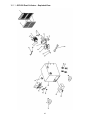
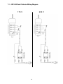
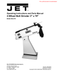
Operating Instructions and Parts Manual
Metal Dust Collector
Model JDC-500
WALTER MEIER (Manufacturing) Inc.
427 New Sanford Road
LaVergne, Tennessee 37086
Ph.: 800-274-6848
www.waltermeier.com
Part No. M-414700
Revision B 09/2012
Copyright © 2012 Walter Meier (Manufacturing) Inc.
1.0 Warranty and service
Walter Meier (Manufacturing) Inc., warrants every product it sells. If one of our tools needs service or repair, one of
our Authorized Service Centers located throughout the United States can give you quick service. In most cases, any
of these Walter Meier Authorized Service Centers can authorize warranty repair, assist you in obtaining parts, or
perform routine maintenance and major repair on your JET® tools. For the name of an Authorized Service Center in
your area call 1-800-274-6848.
MORE INFORMATION
Walter Meier is consistently adding new products to the line. For complete, up-to-date product information, check with
your local Walter Meier distributor, or visit waltermeier.com.
WARRANTY
JET products carry a limited warranty which varies in duration based upon the product (MW = Metalworking, WW =
Woodworking).
WHAT IS COVERED?
This warranty covers any defects in workmanship or materials subject to the exceptions stated below. Cutting tools,
abrasives and other consumables are excluded from warranty coverage.
WHO IS COVERED?
This warranty covers only the initial purchaser of the product.
WHAT IS THE PERIOD OF COVERAGE?
The general JET warranty lasts for the time period specified in the product literature of each product.
WHAT IS NOT COVERED?
Five Year Warranties do not cover woodworking (WW) products used for commercial, industrial or educational
purposes. Woodworking products with Five Year Warranties that are used for commercial, industrial or education
purposes revert to a One Year Warranty. This warranty does not cover defects due directly or indirectly to misuse,
abuse, negligence or accidents, normal wear-and-tear, improper repair or alterations, or lack of maintenance.
HOW TO GET SERVICE
The product or part must be returned for examination, postage prepaid, to a location designated by us. For the name
of the location nearest you, please call 1-800-274-6848.
You must provide proof of initial purchase date and an explanation of the complaint must accompany the
merchandise. If our inspection discloses a defect, we will repair or replace the product, or refund the purchase price,
at our option. We will return the repaired product or replacement at our expense unless it is determined by us that
there is no defect, or that the defect resulted from causes not within the scope of our warranty in which case we will,
at your direction, dispose of or return the product. In the event you choose to have the product returned, you will be
responsible for the shipping and handling costs of the return.
HOW STATE LAW APPLIES
This warranty gives you specific legal rights; you may also have other rights which vary from state to state.
LIMITATIONS ON THIS WARRANTY
WALTER MEIER (MANUFACTURING) INC., LIMITS ALL IMPLIED WARRANTIES TO THE PERIOD OF THE
LIMITED WARRANTY FOR EACH PRODUCT. EXCEPT AS STATED HEREIN, ANY IMPLIED WARRANTIES OR
MERCHANTABILITY AND FITNESS ARE EXCLUDED. SOME STATES DO NOT ALLOW LIMITATIONS ON HOW
LONG THE IMPLIED WARRANTY LASTS, SO THE ABOVE LIMITATION MAY NOT APPLY TO YOU.
WALTER MEIER SHALL IN NO EVENT BE LIABLE FOR DEATH, INJURIES TO PERSONS OR PROPERTY, OR
FOR INCIDENTAL, CONTINGENT, SPECIAL, OR CONSEQUENTIAL DAMAGES ARISING FROM THE USE OF
OUR PRODUCTS. SOME STATES DO NOT ALLOW THE EXCLUSION OR LIMITATION OF INCIDENTAL OR
CONSEQUENTIAL DAMAGES, SO THE ABOVE LIMITATION OR EXCLUSION MAY NOT APPLY TO YOU.
Walter Meier sells through distributors only. The specifications in Walter Meier catalogs are given as general
information and are not binding. Members of Walter Meier reserve the right to effect at any time, without prior notice,
those alterations to parts, fittings, and accessory equipment which they may deem necessary for any reason
whatsoever. JET® branded products are not sold in Canada by Walter Meier.
2
2.0 Table of contents
Section
Page
1.0 Warranty and service ........................................................................................................................ 2
2.0 Table of contents .............................................................................................................................. 3
3.0 Safety warnings ................................................................................................................................ 4
4.0 About this manual ............................................................................................................................. 5
5.0 Specifications ................................................................................................................................... 6
6.0 Setup and assembly ......................................................................................................................... 7
7.0 Electrical connections ....................................................................................................................... 7
7.1 Grounding instructions................................................................................................................... 7
7.2 Voltage conversion ........................................................................................................................ 8
7.3 Extension cords............................................................................................................................. 8
8.0 Operation.......................................................................................................................................... 8
8.1 Control switch ............................................................................................................................... 8
9.0 Maintenance ..................................................................................................................................... 9
10.0 Replacement Parts ......................................................................................................................... 9
10.1.1 JDC-500 Dust Collector – Exploded View ............................................................................... 10
10.1.2 JDC-500 Dust Collector – Parts List ........................................................................................ 11
11.0 JDC-500 Dust Collector Wiring Diagram........................................................................................ 12
3
12. Keep safety guards in place at all times when the
machine is in use. If removed for maintenance
purposes, use extreme caution and replace the
guards immediately after completion of
maintenance.
3.0 Safety warnings
1.
Read and understand the entire owner's manual
before attempting assembly or operation.
2.
Read and understand the warnings posted on the
machine and in this manual. Failure to comply
with all of these warnings may cause serious
injury.
3.
Replace the warning labels if they become
obscured or removed.
4.
Do not use this metal dust collector for other than
its intended use. If used for other purposes,
Walter Meier (Manufacturing) Inc., disclaims any
real or implied warranty and holds itself harmless
from any injury that may result from that use.
5.
13. Check damaged parts. Before further use of the
machine, a guard or other part that is damaged
should be carefully checked to determine that it
will operate properly and perform its intended
function. Check for alignment of moving parts,
binding of moving parts, breakage of parts,
mounting and any other conditions that may
affect its operation. A guard or other part that is
damaged should be properly repaired or
replaced.
14. Provide for adequate space surrounding work
area and non-glare, overhead lighting.
15. Keep the floor around the machine clean and free
of scrap material, oil and grease.
16. Keep visitors a safe distance from the work area.
Keep children away.
Some dust created by power sanding, sawing,
grinding, drilling and other construction activities
contain chemicals known to cause cancer, birth
defects or other reproductive harm. Some
examples of these chemicals are:
•
Lead from lead based paint.
•
Crystalline silica from bricks, cement and
other masonry products.
17. Make your workshop child proof with padlocks,
master switches or by removing starter keys.
18. Give your work undivided attention. Looking
around, carrying on a conversation and “horseplay” are careless acts that can result in serious
injury.
19. Use the right tool at the correct speed and feed
rate. Do not force a tool or attachment to do a job
for which it was not designed. The right tool will
do the job better and more safely.
•
Arsenic and chromium from chemically
treated lumber.
Your risk of exposure varies, depending on how
often you do this type of work. To reduce your
exposure to these chemicals, work in a wellventilated area and work with approved safety
equipment, such as face or dust masks that are
specifically designed to filter out microscopic
particles.
6.
Make certain the switch is in the OFF position
before connecting the machine to the power
supply.
7.
Wear approved safety glasses/face shields while
using and cleaning this machine. Everyday
eyeglasses only have impact resistant lenses;
they are not safety glasses.
8.
Wear ear protectors (plugs or muffs) during
extended periods of operation.
9.
Make certain the machine is properly grounded.
20. Use recommended accessories;
accessories may be hazardous.
improper
21. Maintain tools with care. Follow instructions for
lubricating and changing accessories.
22. Turn off the machine before cleaning. Use a
brush or compressed air to remove chips or
debris — do not use your hands.
23. Do not stand on the machine. Serious injury
could occur if the machine tips over.
24. Never leave the machine running unattended.
Turn the power off and do not leave the machine
until it comes to a complete stop.
25. Remove loose items and unnecessary work
pieces from the area before starting the machine.
26. Do not use this machine in damp or wet
locations, or expose it to rain. Keep work area
well lighted.
10. Make all machine adjustments or maintenance
with the machine unplugged from the power
source.
27. Do not use this dust collector to pick up
flammable or combustible liquids, and do not use
it in explosive environments.
11. Remove adjusting keys and wrenches. Form a
habit of checking to see that keys and adjusting
wrenches are removed from the machine before
turning it on.
4
28. Do not use the dust collector to dissipate fumes
or smoke. Never pick up anything that is burning
or smoking, such as cigarettes, matches, or hot
ashes.
30. Do not unplug the machine by pulling on the
power cord – grasp the plug, not the cord.
31. Do not pull the machine by the power cord, or
allow the power cord to contact sharp edges or
hot surfaces. Replace a damaged cord
immediately.
29. Do not insert fingers or foreign objects into the
inlet ports. Keep hair, loose clothing, and all body
parts away from openings and moving parts of
the dust collector.
Familiarize yourself with the following safety notices used in this manual:
This means that if precautions are not heeded, it may result in minor injury and/or
possible machine damage.
This means that if precautions are not heeded, it may result in serious injury or possibly
even death.
4.0 About this manual
This manual is provided by Walter Meier (Manufacturing) Inc. covering the safe operation and
maintenance procedures for a JET Model JDC-500 Metal Dust Collector. This manual contains
instructions on installation, safety precautions, general operating procedures, maintenance instructions
and parts breakdown. Your machine has been designed and constructed to provide years of trouble-free
operation if used in accordance with instructions as set forth in this document.
If there are questions or comments, please contact your local supplier or Walter Meier. Walter Meier can
also be reached at our web site: www.waltermeier.com.
Retain this manual for future reference. If the machine transfers ownership, the manual should
accompany it.
Read and understand the entire contents of this manual before attempting
assembly or operation. Failure to comply may cause serious injury.
5
5.0 Specifications
Model number ............................................................................................................................................. JDC-500
Stock numbers:
Dust collector............................................................................................................................................ 414700
Replacement filters (set of 2)..................................................................................................................... 414705
Motor and electricals:
Motor type ............................................................................ totally enclosed fan cooled, induction, capacitor start
Horsepower ................................................................................................................................. 1.5 HP (1.1 kW)
Phase......................................................................................................................................................... single
Voltage........................................................................................................................ 115/230V (prewired 115V)
Cycle........................................................................................................................................................... 60Hz
Listed FLA (full load amps)............................................................................................... 15A(115V) / 7.5A(230V)
Start capacitor ......................................................................................................................... 300MFD/ 125VAC
Run capacitor ...................................................................................................................................... 30μf/250V
On/off switch ................................................................................................ magnetic, with removable safety key
Motor speed ........................................................................................................................................ 1450RPM
Power cord length............................................................................................................................ 6 ft. (183 cm)
Power plug installed........................................................................................................................................ yes
1
Recommended circuit size ........................................................................................ 20A for 115V; 15A for 230V
1
Recommended fuse/breaker size ................................................................................ 30A for 115V; 20A for 30V
Noise emission .................................................................................................. 75 dB at 5 ft. (152.4 cm) from fan
Materials:
Cabinet ........................................................................................................................................................ steel
Impeller and housing...................................................................................................... aluminum (non-sparking)
Casters ........................................................................................................................................... polyurethane
Filters ........................................................................................................................................ micro steel mesh
Other:
Maximum capacity ............................................................................................................... 490 cfm (13.88 cmm)
Maximum hose velocity.......................................................................................................5610 fpm (1710 mpm)
Number of filters ................................................................................................................................................ 2
Filter size.............................................................................................. 19”L x 9.5”w x 2”Thk (483 x 241 x 51 mm)
Filter efficiency .............................................................................................................. 99% of 5 micron particles
Number of dust ports ......................................................................................................................................... 2
Dust port outside diameter .................................................................................................................4” (100 mm)
Dust port outside diameter with adaptor ............................................................................................... 2” (50 mm)
Casters ............................................................................................................... 2-1/2” (64 mm) diameter, swivel
Dimensions:
Dimensions, shipping ........................................................................ 32” L x 28”W x 30.9”H (813 x 711 x 785 mm)
Dimensions, assembled ............................................................... 30.5”L x 31.5”W x 31.5”H (775 x 800 x 800 mm)
Impeller diameter ............................................................................................................................. 11” (279 mm)
Weights:
Net ................................................................................................................................................. 157 lb (71 kg)
Shipping ........................................................................................................................................ 192lb (87.2kg)
1
subject to local and national electrical codes.
The specifications in this manual were current at time of publication, but because of our policy of continuous
improvement, Walter Meier (Manufacturing) Inc., reserves the right to change specifications at any time and without
prior notice, without incurring obligations.
6
7.1 Grounding instructions
6.0 Setup and assembly
1. All Grounded, Cord-connected Tools:
Carton contents:
1
2
2
4
16
1
In the event of a malfunction or breakdown,
grounding provides a path of least resistance for
electric current to reduce the risk of electric
shock. This tool is equipped with an electric cord
having an equipment-grounding conductor and a
grounding plug. The plug must be plugged into a
matching outlet that is properly installed and
grounded in accordance with all local codes and
ordinances.
Dust Collector
4” to 3” adaptors
Filters (pre-installed)
Caster assemblies
Washer Head Screws, 5/16” x 1/2"
Open End Wrench, 10-12mm
Do not modify the plug provided - if it will not fit
the outlet, have the proper outlet installed by a
qualified electrician.
Improper connection of the equipmentgrounding conductor can result in a risk of
electric shock. The conductor with insulation
having an outer surface that is green with or
without yellow stripes is the equipmentgrounding conductor. If repair or replacement of
the electric cord or plug is necessary, do not
connect the equipment-grounding conductor to a
live terminal.
Check with a qualified
electrician or service personnel if the
grounding instructions are not completely
understood, or if in doubt as to whether the
tool is properly grounded. Failure to comply
may cause serious or fatal injury.
Use only 3-wire extension cords that have 3prong grounding plugs and 3-pole receptacles
that accept the tool's plug.
Figure 1
1.
Repair or replace damaged or worn cord
immediately.
Turn dust collector upside down, with help
from an assistant. Assemble casters to plates
with the washer head screws. See Figure 1.
2. Grounded, cord-connected tools intended for
use on a supply circuit having a nominal rating
less than 150 volts:
This tool is intended for use on a circuit that has
an outlet that looks like the one illustrated in A,
Figure 2. An adapter, shown in B and C, may be
used to connect this plug to a 2-pole receptacle
as shown in B if a properly grounded outlet is
not available. The temporary adapter should be
used only until a properly grounded outlet can
be installed by a qualified electrician. This
adapter is not permitted in Canada. The greencolored rigid ear, lug, and the like, extending
from the adapter must be connected to a
permanent ground such as a properly grounded
outlet box.
7.0 Electrical connections
The JDC-500 Dust Collector is rated at
115/230V power, pre-wired for 115 volt, and
supplied with a plug.
Before connecting to power source, be sure
switch is in off position.
It is recommended that the dust collector, when
operated on 115 volt power, be connected to a
dedicated 20 amp circuit with a 30 amp circuit
breaker or time-delay fuse marked “D”. When
operated on 230 volt power, it is recommended
that the dust collector be connected to a
dedicated 15 amp circuit with a 20 amp circuit
breaker or time-delay fuse marked “D”. Local
codes take precedence over recommendations.
3. Grounded, cord-connected tools intended for
use on a supply circuit having a nominal rating
between 150 - 250 volts, inclusive:
7
This tool is intended for use on a circuit that has
an outlet that looks like the one illustrated in D,
Figure 2. The tool has a grounding plug that
looks like the plug illustrated in D. Make sure the
tool is connected to an outlet having the same
configuration as the plug. No adapter is
available or should be used with this tool. If the
tool must be reconnected for use on a different
type of electric circuit, the reconnection should
be made by qualified service personnel; and
after reconnection, the tool should comply with
all local codes and ordinances.
Ampere
Rating
Volts
Total length of
cord in feet
120
240
25
50
50
100
100
200
AWG
150
300
More
Than
Not
More
Than
00
06
18
16
16
14
06
10
18
16
14
12
10
12
16
16
12
16
14
12
14
12
Not
Recommended
Extension Cord Recommendations
Table 1
8.0 Operation
8.1 Control switch
Refer to Figure 3.
The green pilot lamp (A) will be illuminated
whenever there is power connected to the
dust collector, not just when the machine is
running. Do not assume that no light means
there is no power to the machine. If the bulb is
bad, there will be no indication. Always check
before use.
Figure 2
7.2 Voltage conversion
To switch the incoming power leads for 230 volt
operation, follow the wiring diagram on the
inside cover of motor junction box. To access
junction box, remove filters and cover (part #1,
section 10.1.1).
Pull out on switch (B) to start machine. Push
switch in to stop.
The safety key (C) prevents unauthorized use of
the machine. Remove this key to deactivate the
switch; insert it to restart.
The plug on the end of the motor cord must be
replaced with a UL/CSA listed plug rated for
240V.
7.3 Extension cords
The use of extension cords is discouraged. Try
to place equipment within reach of the power
source. If an extension cord is necessary, make
sure it is in good condition and heavy enough to
carry the current your product will draw. An
undersized cord will cause a drop in line voltage
resulting in loss of power and overheating. Table
1 shows correct size to use depending on cord
length and nameplate ampere rating. If in doubt,
use the next heavier gauge. The smaller the
gauge number, the heavier the cord.
Figure 3
8
9.0 Maintenance
Periodically empty the chip drawer, and clean
out the interior of the dust collector.
Keep the fan end of the motor clear of dust and
debris.
Replace filters after maximum 800 hours of use.
See Figure 4.
Figure 4
10.0 Replacement Parts
Replacement parts are listed on the following pages. To order parts or reach our service department, call
1-800-274-6848 Monday through Friday (see our website for business hours, www.waltermeier.com).
Having the Model Number and Serial Number of your machine available when you call will allow us to
serve you quickly and accurately.
9
10.1.1 JDC-500 Dust Collector – Exploded View
10
10.1.2 JDC-500 Dust Collector – Parts List
Index No Part No
Description
Size
Qty
1............... JDC-500001.............Front Cover ........................................................................................... 1
................. JDC-500001A ..........Front Cover (serial no 1210047 & higher) ................................................... 1
2............... JDC-500002.............Motor..................................................................1.5HP 115/230V ......... 1
................. JDC-500002-MF ......Motor Fan (not shown) ........................................................................... 1
................. JDC-500002-MFC ....Motor Fan Cover (not shown) ................................................................ 1
................. JDC-500002-JB .......Junction Box with cover (not shown) ...................................................... 1
................. JDC-500002-SC.......Start Capacitor .................................................125VAC/300MFD ....... 1
................. JDC-500002-RC ......Run Capacitor ....................................................250VAC/30μf .............. 1
3............... TS-0680031 .............Flat Washer ........................................................5/16” .......................... 8
4............... TS-0051051 .............Hex Cap Screw ..................................................5/16”x1” ..................... 1
5............... JDC-500005.............Key.....................................................................6x6x25 mm................. 1
6............... JDC-500006.............Motor Packing ....................................................................................... 1
7............... JDC-500007.............Canister Housing ................................................................................... 1
8............... JDC-500008.............Motor Cord ............................................................................................ 1
9......GH1340A-TBCP-16-04 ......Open End Wrench .............................................10/12mm .................... 1
10 ............. TS-1533032 .............Pan Head Screw ................................................M5x10 ........................ 3
11 ............. TS-0570021 .............Hex Nut ..............................................................5/16” .......................... 4
12 ............. JDC-500012.............Set Screw...........................................................5/16”x5/16”................. 1
13 ............. JDC-500013.............Impeller ..............................................................Ø11”........................... 1
14 ............. JDC-500014.............Washer.................................................................................................. 1
15 ............. TS-1503051 .............Socket Head Cap Screw.....................................M6x20 ........................ 1
16 ............. JDC-500016.............Hose Adaptor .....................................................4” to 3” ....................... 2
................. JDC-500016A ..........Hose Adaptor (serial no 1210047 & higher) ...........4” to 2”........................ 2
................. JDC-500016B ..........Hose Adaptor (serial no xxxx067 & higher) .............3” to 2”........................ 2
17 ............. JDC-500017.............Phillips Head Screw............................................3/16”x3/8” .................. 2
19 ............. JDC-500019.............Handle................................................................................................... 2
20 ............. JDC-500020.............Tapping Screw ...................................................................................... 4
21 ............. JDC-500021.............Phillips Head Screw............................................3/16”x3/8” .................. 3
22 ............. JDC-500022.............Pull-Out Switch ...................................................................................... 1
................. JDC-500022-SC.......Safety Key ............................................................................................. 1
24 ............. JDC-500024.............Strain Relief ........................................................PG-16......................... 3
25 ............. JDC-500025.............External Tooth Lock Washer ...............................3/16” .......................... 1
26 ............. JDC-500026.............Power Cord ........................................................................................... 1
28 ............. JDC-500028.............Main Housing ........................................................................................ 1
................. JDC-500028A ..........Main Housing (serial no 1210047 & higher) ................................................ 1
29 ............. JDC-500029.............Drawer .................................................................................................. 1
30 ............. JDC-500030.............Drawer Handle ...................................................................................... 1
31 ............. JDC-500031.............Washer Head Screw...........................................5/16”x1/2” ................ 16
32 ............. JDC-500032.............Swivel Caster .....................................................Ø 2-1/2”...................... 4
34 ............. JDC-500034.............Phillips Head Screw............................................1/4”x5/8” .................... 2
35 ............. 414705 ....................Filter (set of 2) ....................................................................................... 2
36 ............. TS-1482021 .............Hex Cap Screw ..................................................M6x12 ........................ 1
37 ............. TS-1482021 .............Hex Cap Screw ..................................................M6x12 ........................ 2
38 ............. JDC-500038.............Bracket .................................................................................................. 1
................. JETLOGO-1 .............JET Logo (not shown).........................................2-3/4”x8” .................... 1
................. STRIPE-1-3/4 ..........JET Stripe (not shown) .......................................1-3/4”W ............... per ft.
................. JDC500-ID ...............I.D. Label (not shown)............................................................................ 1
................. JDC500-CL ..............Caution Label (not shown) ..................................................................... 1
11
11.0 JDC-500 Dust Collector Wiring Diagram
115 V
230 V
12