1
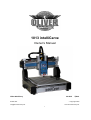
1013 intelliCarve Owner’s Manual Oliver Machinery M-1013 7/2011 Copyright 2003 Seattle, WA [email protected] www.olivermachinery.net 1 Warranty Oliver makes every effort possible to assure that its equipment meets the highest possible standards of quality and durability. All products sold by Oliver are warranted to the original customer to be free from defects for a period of 2 (two) years on all parts, excluding electronics and motors, which are warranted for 1 year. Oliver’s obligation under this warranty shall be exclusively limited to repairing or replacing (at Oliver’s option) products which are determined by Oliver to be defective upon delivery F.O.B. (return freight paid by customer) to Oliver, and on inspection by Oliver. This warranty does not apply to defects due, directly or indirectly, to misuse, abuse, negligence, accidents, unauthorized repairs, alterations, lack of maintenance, acts of nature, or items that would normally be consumed or require replacement due to normal wear. In no event shall Oliver be liable for death, personal or property injury, or damages arising from the use of its products. Warning Read this manual thoroughly before operating the machine. machines that have been altered or abused. Oliver Machinery disclaims any liability for Oliver Machinery reserves the right to effect at any time, without prior notice, those alterations to parts, fittings, and accessory equipment which they may deem necessary for any reason whatsoever. For More Information Oliver Machinery is always adding new Industrial Woodworking products to the line. up-to-date product information, check with your www.olivermachinery.net 2 local Oliver For complete, Machinery distributor, or visit WARNING Read this manual completely and observe all warning labels on the machine. Oliver Machinery has made every attempt to provide a safe, reliable, easy-to-use piece of machinery. Safety, however, is ultimately the responsibility of the individual machine operator. As with any piece of machinery, the operator must exercise caution, patience, and common sense to safely run the machine. Before operating this product, become familiar with the safety rules in the following sections. This machine is designed for acrylic and wood carving only. This unit cannot be modified and used for any application other than for which it is designed. Any modification may result in a serious injury and will void all warranties. Please read and understand all warnings and operating instructions. Basic safety precautions should be followed to avoid the risk of personal injury when operating the machine. 1. Do not block the Emergency Stop Button. 2. To reduce the risk of electric shock, do not operate the machine with wet hands. 3. Do not wear gloves when operating the machine. 4. Before turning the power on, make sure the surroundings are clear of obstacles. 5. When you turn the power on, the axis return to the Home Point coordinates automatically. 6. Avoid the risk of danger; not play or run in the work area. 7. Do not touch the spindle or cutting tools with bare hands before the machine is completely stopped. 8. Pay attention to the warning labels. Replace the warning labels if they become illegible or are missing. 9. Always power off the machine when you finish your work. 10. Please install and remove the bit as instructed. 11. Ensure the power is off before installing a new cutting tool. 12. Please install the software and the unit as instructed. 13. To avoid the risk of danger, make certain that the object you are carving is properly secured. 14. Do not remove any debris that cover the axis while the unit is operating. 15. Always ensure that the size of the workpiece is proper for intelliCarve. 16. To ensure safety, all maintenance should be made by a knowledgeable technician. 17. To ensure safety, be sure to properly ground any extension cord that is used. 18. To ensure safety, do not tamper with the safety cover, limit switch or any other accessories. 19. To avoid electrical shock, do not touch transformers, motors and control box when the power is on. 20. Unplug the power before replacing any fuse. Be sure to use the recommended fuse. 21. Be sure to turn off the machine when the power source is unstable. 22. Be sure to keep a record before changing any settings of the machine. 23. Place the unit in a sturdy place and dry area. 24. Avoid extremely high temperatures. 3 Table of Contents Page Number Warranty .................................................................................................................................................2 Safety and Warnings..............................................................................................................................3 Table of Contents ...................................................................................................................................4 Overview.................................................................................................................................................5 Specifications......................................................................................................................................7-8 Unpacking Your intelliCarve ..................................................................................................................9 Standard Packaging ..............................................................................................................9 Getting to Know Your intelliCarve .................................................................................................. 10-11 The Components.................................................................................................................10 X/Y/Z Axis System............................................................................................................... 11 Install The Cutting Tool........................................................................................................................12 Cutting Tools ...................................................................................................................................13-14 Conical Bit...........................................................................................................................13 End Mill Bit ..........................................................................................................................14 Installing i-Picture Software ................................................................................................................15 Using i-Picture.................................................................................................................................15-18 Getting Ready To Carve ................................................................................................................19-23 Powering Up .......................................................................................................................19 Setting the Work Piece On The Table ...................................................................................20 Using The Control Panel..................................................................................................21-23 Tips .......................................................................................................................................................24 Advanced Operations .....................................................................................................................25-28 CAD/CAM Software ..............................................................................................................25 Origin Repeat .......................................................................................................................25 Positioning By Coordinate.....................................................................................................26 Turn Spindle On/Off In Manual Jog Mode..............................................................................27 Changing Units from Metric to Imperial .................................................................................28 Troubleshooting..............................................................................................................................29-38 4 Overview Software i-Picture is free software for the intelliCarve series that can automatically output NC code from image files such as jpg, png, gif or bmp files. Oliver Machinery will continue to review the software and will provide new releases when available at no charge to the original owner. intelliCarve With the output NC code from i-Picture, the intelliCarve is a very unique engraving machine that allows the user to transfer digital images or photographs onto a material such as wood, corian, acrylic or plastic. What makes the intelliCarve so unique? 1. Easy intelliCarve users only need plug the USB into the intelliCarve, then select a file for carving and push a few buttons to complete the carving. Knowledge of CAD/CAM software is not necessary. 2. Light i-Picture comes free with the intelliCarve and does not need a high level computer system to operate such as what is usually needed for CAD/CAM software. And iCarver is only 62lbs! 3. Versatile Easily make highly detailed lithophanes from digital photographs or carve 3D relief carvings from the included library of 3D gray scale images. 5 Technical Features Easy picture engraving by i-Picture’s intuitive picture to g-code convertor File transferred to intelliCarve via USB flash drive Pause function during carving Repeatable origin Adjustable jog speed in manual mode Adjustable carving speed Metric/Imperial system available Supports manual carving without program Maximum engraving area simulation Supports file category tree structure Spindle and stepper motors overload protection Support images in bmp/jpg/gif/png format Percentage display for carving time completion Auto parameters optimization Reliable BLDC (brushless, DC) spindle motor Wood/plastic engraving Dust impact free drive structure Light aluminum ght structure 6 Specifications 1013 intelliCarve Item Description Spec 1 Travel 1.1 X axis 331mm(13") 1.2 Y axis 457mm(18") 1.3 Z axis 76mm(3") 2 Tool 2.1 shank OD ¼” 2.1 cutter conical R1/32” (0.8mm) / end mill D1/8” (3.2mm) 2.2 Cut depth Max 25.4mm(1") 3 Spindle 3.1 speed 15000rpm 3.2 motor 150w DC brushless 4 Transmission 4.1 X/Z lead screw diameter 16mm(0.63”) 4.2 X/Z rail material IGUS WX-01-10 4.3 Y axis Rack & pinion 6 Feed Speed 6.1 speed 3M/min(118in/min) 6.2 position accuracy 0.1mm (0.004”) 6.2 reposition accuracy ±0.1mm (0.004”) 7 Step motor 7.1 Max torque 17.3 kg-cm(15lb-in) 7.2 step angle 1.8 ° 7.3 voltage(Max.) 24V/Phase 7.4 current(Max.) 2.8 A/Phase 8 8.1 9 Sensor no of sensors(X/Y/Z) 2/2/2 Control Interface 9.1 LCD (46x30)mm 9.4 keypad 10 keys 9.6 interface USB Port × 1 7 Specifications (cont.) 10 Dimension & Weight 10.2 Space (WxL) 630x560x530mm(25.8x22.0x20.8”) 10.3 weight 28 Kg 11 Others 11.1 power in AC 110V 6A 50~60Hz 11.3 software i-Picture for intelliCarve 8 61.6lbs Unpacking Your intelliCarve Please unpack your intelliCarve with care. If you discover the machine has been damaged, please report the damage to the freight carrier. Standard Packaging 1. Tool Box 2. USB flash drive 6. End mill bit, 3.2mm Diameter - I-picture software 7. 4mm T wrench - 3D sample pictures 8. 5mm Hex wrench 3. ¼” collet 9. Double wrench 11*13mm 4. Collet nut 10. Double wrench 14*17mm 5. Conical bit, 0.8mm Radius 9 Getting to Know Your intelliCarve Fig. 2 Fig. 3 The Components (see Fig. 2-3) 1. Spindle motor 7. Emergency stop 2. Spindle lock 8. Power switch 3. Table 9. USB port 4. Work piece hold downs 10. Lift handle (left) 5. Lift handle (right) 6. LCD display and controller 10 The Axis System The axis movements are defined according to the operator’s position (facing the front spindle). Keypad Functions 1. + X: spindle head moves right 2. - X: spindle head moves left. 3. +Z: spindle head moves up. 4. - Z: spindle head moves down. 5. +Y: table moves toward operator. 6. - Y: table moves away from operator. 11 Installing the Cutting Tool 1 2 3 4 Press pin slightly. Rotate spindle while pressing the pin in order to engage the lock. Loosen the nut with an open end wrench turning clockwise. Release the bit. To install a new bit, place the 5 collet into the nut. Then put the bit into the nut and collet. Screw the assembly onto the spindle. 6 12 Lock the bit with an open end wrench turning counterclockwise. Cutting Tools Conical Bit Tool Model No. 381044-000 • Material: Carbide • Flute: 2 • Flute length: 1” / Cut depth: Max 1” • Shank diameter: ¼” • Overall length: 2.36” • Cutting edge radius: 0.8mm • Various types of woods. • Recommended max depth of cut per cycle: ½” for Pine; 3/8” for Oak 13 Cutting Tools (cont.) End Mill Bit Tool model No. 381020-000 • Material: Carbide • Flute: 2 • Flute length: 0.47”/ Cut depth: Max 0.45” • Shank diameter: ¼” • End mill diameter: 3.175mm • Overall length: 2.36” • Various types of woods. • Max depth of cut per cycle: 1/8” for Pine; 1/8” for Oak 14 Installing i-Picture Software (Recommended Operating System – Windows XP, Vista or 7) When you purchase the intelliCarve, it comes with i-Picture software. i-Picture converts your image files (gif, png, bmp & jpg) to a .gee file in order for intelliCarve to perform. To begin using i-Picture software it first must be loaded into your personal computer. port of your personal computer. installation. Locate the thumb drive from the toolbox and insert it into the USB Locate the executable file labeled i-Picture_v1.2.exe and click to begin Follow the prompts to complete the installation. Using i-Picture 1. Opening a File Start i-Picture. Under the File tab, click Open Image File, to upload your image file. Allowable formats for pixel files are gif, png, bmp, and jpg files. To open a G code file, click Open G Code under the File tab. Allowable formats for G Code files are nc, txt, and dat files (see Advanced Operation Section). 15 Using i-Picture (cont.) 2. Settings Unit: [mm] or [inch] measurement Size of Project is the carving size that you wish to appear on your workpiece. The boxes represent X/Y/Z = width/length/depth of cut. When you input a number in X, Y will be set automatically according to the ratio of your image. be set automatically. Similarly, when you input a number in Y, X will The maximum allowable dimensions are X=13”(330.2mm), or Y=18”(457.2mm) and Z=3”(76.2mm). The intelliCarve will not operate with values greater than these. Warning: Make sure your work piece is thicker than the dimension you set for the Z-axis otherwise machine damage will occur. Use a sacrificial board if cutting through your work piece is required. Invert light / dark area is to invert concave and convex. When a grayscale image is uploaded, I-Picture defines the darker area as the deeper depth of cut, whereas the lighter area as the shallower depth of cut. Invert will reverse this which is handy for working with lithophanes. Scan step is the distance the Y axis moves on every carving along the X axis. The lower number the Scan step is, the more detailed your image will be but the longer it will take to produce. Default is 0.2 (mm). Tool Type: a. GVee_0.5: conical cutter [Metric]. Cutting Edge Radius: 0.5mm. Type-A1 Tool model no: 380959-000. b. GVee_0.8: conical cutter [Metric]. Cutting Edge Radius: 0.8mm. Type-A2 Tool Model no: 380993-000. c. GVee_1/50”: conical cutter [English]. Cutting Edge Radius: 1/50”. Type-A3 Tool Model No: 381018-000 d. GVee_1/32”: conical cutter [English]. Cutting Edge Radius: 1/32”.Type-A4 Tool Model No: 381044-000. e. Endmill_3.2: end mill [Metric System]. Flat diameter: 3.2mm. Type-B1 Tool Model No: 380961-000. f. Endmill_D_1/8”: end mill [English]. Flat diameter: 1/8”.Type-B2 Tool Model No: 381020-000. Feed Depth per Cycle is the depth of cut (Z axis) per cycle. The default is set to be 24mm, but it is adjustable. For example: when Z is 10mm and Feed Depth per Cycle is 24mm, the cutter will carve the workpiece in a single pass. Conversely, when Z is 10mm and Feed Depth per Cycle is 5mm, the cutter will carve the workpiece twice (2 passes) in order to meet Z depth (per cycle= 5mm; two cycles = 10mm). 16 Settings (cont.) XY Origin Position represents your picture and how it will be oriented on your work piece. (However this will ultimately be determined when you set the spindle to your preferred starting point on the work piece, but this will be discussed later in section 7.) If using a single piece of material for one carving it may be advantageous to start in the center as this is an easy point to find on your material. However, if carving several objects on one piece of material it might make sense to start in one of the corners in order to ‘nest’ the projects. a. Center b. Upper Left c. Upper Right d. Lower Left e. Lower Right Preview allows you to preview your project before saving: Preview 17 Using i-Picture (cont.) 3. Converting a file Once your settings have been entered it is time to convert the image to a .gee code file. Click Convert to save the file in [.gee] format. A screen will pop up saying ‘It will take a few minutes, please Wait’ and in a few moments you will see a blue progress bar begin. When finished the following screen will appear prompting you to save the file: Here you can change the File name and save the file in a location of your choosing on your computer. When you wish to actually carve the file, simply copy the file from the location it was saved to the flash drive and insert it in the USB port of the intelliCarve. 18 Getting Ready to Carve Powering Up the intelliCarve **Ensure carving bit is secure in machine before proceeding** 1. Insert the flash drive into the USB slot. (see picture ‘A’) 2. Rotate emergency stop button clockwise to release. (see picture ‘B’) 3. Turn rocker swith to on position. (see picture ‘B’) Picture A Picture B 19 Setting Up To Carve (cont.) Setting the work piece on the table The left fence with the ruler represents the Y-axis. the minimum and maximum dimension on the ruler. Make sure that the Y dimension of your carving is within It is important for the work piece to be held securely in position on the work table. Two hold-downs are supplied with the machine to accomplish this. First place the work piece against the fence (D) as shown in the picture below. Slide the hold down (A) up to the work piece leaving approximately 1/16”-1/8” between the base of the hold down and the work piece. into position with the wing nut (B). in position. Lock the hold down Finally, turn the cap screw (C) clockwise until the work piece is held firmly Repeat the procedure for the second hold down. 20 Setting Up To Carve (cont.) Using the control panel 1. When you first turn the machine on you will notice 4. The next screen to appear is the main operating the control panel display will read: screen as seen below. Use the arrow button on the controller to set the cursor to ‘Select file’ as shown: Pressing on the keypad will automati- cally start the spindle toward its home point (X=0, Press to continue. Y=0, Z=0). 5. Use the arrow buttons to scroll up or down to the desired file as indicated by the cursor (this is the file you converted from i-Picture and copied to the flash 2. After the spindle reaches its home point, the drive). display will read: as shown: Press to continue. Press In this case the file is called ‘GCODE.GEE’ to continue. 6. Select ‘Manual Jog Mode’ as show: 3. The next three screens will prompt you to check: a. Is the ‘cutting tool’ is secure? b. Is the ‘workpiece’ secure? c. Is the flash drive in the ‘USB’ port? Press after confirming each of these. Press 21 to continue. Using the control panel (cont.) 7. Once in ‘Manual Jog Mode’ it is time to move the spindle to the ‘Origin Point’. This is the point that corresponds with the selected ‘XY origin position’ chosen in i-Picture. position as the origin point. In this example we will use the ‘center’ Again, make sure that the Y dimension of your carving is between the minimum and maximum of the ruler on the fence. Use the X,Y and Z plus and minus keys to move the spindle to the center of your work piece. Note that for the Z axis, move the spindle so that the tip of the cutting tool just touches the work piece surface. Press to continue 8. Once the spindle is in position move the cursor using the arrow buttons on the keypad to ‘Enter to set ORG’ as shown: Press to set the carving origin point and again to continue. 22 Using the control panel (cont.) 9. The screen will now show the X,Y,Z origin points confirmation set to zero: 10. Press the ‘BACK’ key on the keypad and the following screen will appear: If you wish to see the spindle travel around the outside border of your carving, move the cursor to ‘Border’ and press. This is helpful if there is concern of the spindle bumping into something. If you wish to continue, move the cursor to ‘Process’ and press 12. The following screen will appear asking you to choose the carving speed. Note: The lower the speed the higher quality the carving will be but the longer it will take. Press to begin carving! 23 Use the up or down arrows to choose. Tips 1. When working with thin materials or cutting through your work piece it becomes necessary to place your project on a sacrificial board to prevent damage to the machine. Double sided tape such as white carpet tape is helpful to secure the pieces together. 2. a) When working with lithophanes keep in mind that your end product will be a mirror image of your photograph. You may wish to reverse your photograph before uploading it to i-Picture. This can be done with photo editing software. (b) It might be handy clicking the Invert box in i-Picture. This will reverse the depth of cut for the dark and light colors allowing for proper shading of your lithophane. (c) Black and white photos or photos that have been converted to grayscale give better results. 24 Advanced Operations CAD/CAM software The 1013 intelliCarve will accept G-code from aftermarket CAD/CAM software programs such as V-Carve Pro or ArtCam. Check with your supplier for the post processor file required for your software to run the intelliCarve. There may be some limits to the projects you can produce due to nature of the Y-axis travel. Possibly, intricate work where fitting with another part is required may be a problem. Oliver Machinery is not responsible for work done using after market CAD/CAM software. Origin repeat If you wish to run the same project again, rather than manually jogging the spindle to the origin point, it is possible to start from the previous origin point: Step 1. After engraving complete, select “Position” and press “enter”. Step 2. If home point was set in last engraving, “Old origin” will prompt up. Step 3. Select “ Old origin” to set engraving origin. Step 4. Press and proceed as usual. 25 Advanced Operations (cont.) Positioning by coordinate input User can move spindle to certain position by coordinate input: Step 1. Select ”Position” and press Step 5. Press up or down key to input coordinate reading, for this example, X axis reading is 103.6. Step 2. Select “coordinate mode” and press Step 6. Press ”Back” key to leave adjustment status Step 3. Select X and press Step 7. Select “Move and Set ORG” Step 4. Cursor turns to block flash for adjustment Step 8. Press “Enter” to move spindle to ( 103.6,0,0) status 26 Advanced Operations (cont.) Turn on/off spindle in manual jog mode The default setting is ‘Spindle Motor Off’ Example: :Turn Spindle Motor On Step 1. Select “Position “and press Step 2. Select “Spindle Motor Off” then press Cursor turns to block flash for adjustment status Step 3. Press up or down key to change status, for this example, press down key to turn on spindle motor *Caution: watch safety issues when spindle motor is turned on *C Step 4. Press “Back” key to leave adjustment status Step 5. Follow the same procedure to turn off spindle motor 27 Advanced Operations (cont.) Imperial / Metric Unit Change The iCarver default unit is Metric scale in mm, unit can be switched to Imperial in inches. Example: Change Unit from Metric (mm) to Imperial (inches) Step 5. Press “Down” key on keypad to change to Step 1. Default is metric unit display: Imperial unit, “Unit:mm” will change to “Unit:in”. Step 2. Select “Configuration” on main manual Step 6. Press “Back” key on keypad, to restore and press cursor from block flash to “→”. Step 3. Select “Unit:mm” and press Step 7. Press “Back” key on keypad to return to the main screen Step 4. Press and cursor turns to block flash which means it is ready The display now is in Imperial inches Unit change is completed. The system will keep this setting after power off. User can follow the same procedure to to edit. set metric unit to mm. Press the up or down key to change the setting from mm to inches. 28 Troubleshooting Operating the unit: Item Problem Check up Solution a. Ensure the power Turn the power switch to switch is turned on. “-” status. Red light indicates b. Ensure the power normal. LED does not switch LED lights Red. come on, indicating malfunction. c. Set off the Press the red button and EMERGENCY STOP turn it clockwise in order Button. to set it off. The unit is not functioning 1 after the power cord is plugged in. The unit will set the 3 d. Press the Start Button (Green color). axes to their home coordinates automatically. Note Contact your local dealer or distributor if this does not help. For your safety, set the button on when not in use. Set the button off in order to carve. Go to [e] if this does not work. e. Ensure the 3 axes are If not, see X/Y/Z in their correct positions. components. Locate the axes to their f. The axes do not stay in their travel areas. travel areas manually. Use the tools that come with the unit to adjust the lead screws. g. Restart the Start Button. Adjust X &Y axes with T & Hex wrench; and/or rotate the screw on Z axis. The unit will set the 3 Contact your local dealer axes to their home or distributor if this does coordinates automatically. not help. If the display shows The display shows signal, 2 but the unit does not function. ■■■■■, reset the Check the display EMERGENCY STOP shows ■■■■■■■■ Button and release it after 10 seconds. Then, turn on the Start Button. 29 Contact your local dealer or distributor if this does not help. Troubleshooting Operating the unit: Item Problem Check up Solution Note Front LEDs light red, 3 Front LEDs light on. Ensure USB Flash drive Reinsert the drive into is inserted. USB port. indicating USB is unable to be read. Contact your local dealer or distributor if this does not help. 4 Control Panel does not Ensure the power is Contact your local dealer function. turned on. or distributor. Restarted the unit, but the 5 Control Panel still does not work. Ensure Control Panel wire is connected. Contact your local dealer Connect the wire. or distributor if this does not help. LEDs light red, indicating Choose “Select File” on the 6 Control Panel, and the front LEDs light red. Ensure USB Flash drive Reinsert the drive into is inserted. USB port. USB is unable to be read. Contact your local dealer or distributor if this does not help. Clean the lead screw & The axes move Select “Position” on the 7 rail in which the axis awkwardly. moves awkwardly. Control Panel, but the axes move improperly. Contact your local dealer The axes do not or distributor if this does function. not help. 30 Contact your local dealer or distributor if this does not help. Troubleshooting During operation: Item Problem Check up Solution Note Ensure axes make a small shift. Time counts down shows on the display. Turn off Emergency Button to stop carving the project. Turn off the power switch in the rear of 1 Select “Enter” to carve, but the unit. axes do not function. Take apart the front cover where the axes locate. Use the T wrench to fix the axes. Check if the motor Ensure terminal pin is wire is loose. tight. Secure the cover back to the place. Then turn Contact your local dealer on the power switch. or distributor if this does Select “Enter” to not help. carve. Turn on Emergency Stop button. Turn off the power switch. Unsecure the nut on Abnormal noise or vibration the bit. 2 occurs while axes are Unload the ER-11 operating. chuck Use wrenches to reinstall the bit. Clean the bit, chuck Use compressed air to and nut. clean sawdust. To lock the bit, push it up. Reinstall the bit. Then, secure the nut. 31 Contact your local dealer or distributor if this does not help. Troubleshooting During operation: Item Problem Check up Solution Note Turn on Emergency Stop button. Turn off the power switch. Unsecure the nut on Use wrenches to re-install the bit the bit. Unload the ER-11 3 Bit breaks while carving. chuck The causes of Bit breaks: To lock the bit, push up Install a new bit. the bit .Then, secure the nut. 1. Cutting depth is overloaded. 2. The hardness of the material is too high. 3. Bit becomes dull. Restart carving your workpiece. 4 5 6 The outcome does not match your computer file. Ensure you install the right size of the bit for your project. Blurriness on your Your workpiece is Use brush to clean the workpiece. composite wood. surface of your workpiece. Lines or curves on your Check the software Clean the rails and lead workpiece. setting and the bit. screws. 32 Contact your local dealer or distributor if this does not help. Troubleshooting (cont.) A) Situation: Power is on, but the unit does not function. Solution: Press the Emergency Stop and turn it clockwise in order to release it. Power switch EMERGENCY STOP B) Situation: Power turned on, but display screen blanks out. Solution #1: Turn off the power and unplug the USB. Restart the power, then plug in the USB into the port. Solution #2: Display screen is capable of presenting 48 files. Keep your files within 48 or reduce root folders on the USB. Display Screen blank 33 C) Display screen shows “Welcome - Enter to Continue”. After pressing “Enter”, the axes return home improperly. Z+ Limit Switch X- Limit Switch Y+ Limit Switch Situation #1: Z axis does not return to home point. Solution: Make Z axis return home by touching Z+ limit switch roller with a tool. Then, restart the machine. Ensure the motor functions and coupling shaft rotates. Go to [Manual Jog Mode] and press Z+ and Z- to move Z axis. Motor Limit switch roller Coupling shaft 34 Situation #2: X or Y axis does not return to home point. Solution: Before checking X/Y axis, ensure [C. situation #1] is fully inspected. Make the spindle return home by touching X- limit switch with a tool. Then, restart the machine. Go to [Manual Jog Mode] and press X+ and X- to move X axis. Ensure the motor functions and coupling shaft rotates. Follow the said procedures to examine Y+ limit switch. X axis step Motor Coupling Shaft Y axis step Motor D) Situation: File loaded and 3 axes operating, but spindle motor does not function. Solution: Go to [Configure \ M3 code] and select [M3 Code: open]. M3 Code close: Spindle Motor turned off M3 Code open: Spindle Motor turned on 35 E) Situation: High pitch sounds from axes. Solution: Clean X & Z screw rods and rails with thinner/lighter lubricant that is equivalent to ISO-32 or lighter than SAE-20. Grease Y axis gear and rack with thicker/heavy lubricants. Clean up excessive oil from gear and rack with clean cloth. DO NOT APPLY DRY CLEAN LUBRICAN. X & Z screw rods and rails Y gear and rack F) Situation: wood chips accumulate on the cutter. Solution: ensure wood fiber texture is paralleled to Y Axis. Wood texture paralleled to X Axis When wood texture is paralleled to X axis, wood chips would accumulate on the cutter. 36 Please place wood piece with its texture paralleled to Y Axis G) Situation: Burrs appear on your project. Solution: Replace the bit. It might be dull or broken. Burrs H) Situation: Burrs on the edge Solution: Use brush to clean the surface/burr. Brush I) Error Codes • Error 1: Limit switch. Causes: X, Y, or Z axis over travels and hits limit switch or its wire is disconnected. Solution: Turn off the power and restart the machine. Then, the axes should function. 37 • Error 12: Spindle motor overheat • Causes: Spindle motor shuts down automatically when overheating. Solution: Turn off the power. Then restart the power after 5 minutes. • Error 13: Spindle motor abnormality Causes: Spindle motor shuts down automatically when disturbances from other sources occurred. Solution: Ensure power supply is earth grounded. Avoid sharing same loop with other equipments. • Error 21: signal abnormality Causes: Wire disconnection between HMI (Human-Machine Interface, refer to the screen and buttons) and PCB (Printed Circuit Board). Solution: Turn off the power and ensure wires are well connected among PCB, HMI and LCD. Restart the machine and it should function. • Error 23: Unable to retrieve data from USB Causes: Misconnected USB or defective USB. Solution: Unplug the USB and restart the machine. Re-plug in the USB. Or replace the USB. • Error 24: PCB abnormality Causes: HMI cannot detect PCB connection. Solution: Turn off the power and ensure wires are well connected among PCB, HMI and LCD. Restart the machine and it should function. • Error 26: HMI abnormality Causes: PCB cannot detect HMI connection. Solution: Turn off the power and ensure wires are well connected among PCB, HMI and LCD. Restart the machine and it should function. ** Please contact your local dealer or distributor for further assistance if the problem persists. ** 38