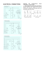
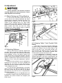
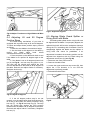
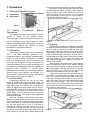
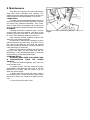
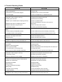
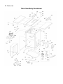
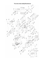
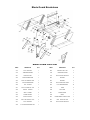
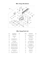
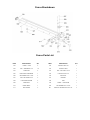
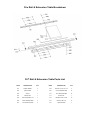
1
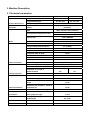
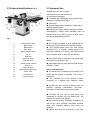
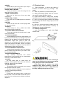
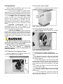
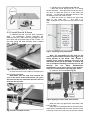
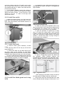
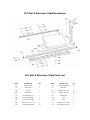
4012 10” Tilting Arbor Tablesaw Owner’s Manual shown with optional 50” rails Oliver Machinery Seattle, WA [email protected] M-4012 06/2012 Copyright 2003 www.olivermachinery.net Warranty Oliver makes every effort possible to assure that its equipment meets the highest possible standards of quality and durability. All products sold by Oliver are warranted to the original customer to be free from defects for a period of 2 (two) years on all parts, excluding electronics and motors, which are warranted for 1 year. Ol er’s bl a n un er s warran s all be ex lus el l e re a r n r re la n a Ol er’s n r u sw are e er ne b Ol er be e e e u n el er F O B (re urn freight paid by customer) to Oliver, and on inspection by Oliver. This warranty does not apply to defects due, directly or indirectly, to misuse, abuse, negligence, accidents, unauthorized repairs, alterations, lack of maintenance, acts of nature, or items that would normally be consumed or require replacement due to normal wear. In no event shall Oliver be liable for death, personal or property injury, or damages arising from the use of its products. Warning Read this manual thoroughly before operating the machine. Oliver Machinery disclaims any liability for machines that have been altered or abused. Oliver Machinery reserves the right to effect at any time, without prior notice, those alterations to parts, fittings, and accessory equipment which they may deem necessary for any reason whatsoever. For More Information Oliver Machinery is always adding new Industrial Woodworking products to the line. For complete, up-todate product information, check with your local Oliver Machinery distributor, or visit www.olivermachinery.net WARNING Read this manual completely and observe all warning labels on the machine. Oliver Machinery has made every attempt to provide a safe, reliable, easy-to-use piece of machinery. Safety, however, is ultimately the responsibility of the individual machine operator. As with any piece of machinery, the operator must exercise caution, patience, and common sense to safely run the machine. Before operating this product, become familiar with the safety rules in the following sections. Always keep guards in place and in proper operating condition. Use blade guard for every applicable operation including all through cuts. If guard is removed for special non-through cuts such as dado and rabbet cuts, replace before further use of the saw. Keep hands out of line with the saw blade. Use a push stick. Do not perform any operation freehand. Never reach around or over the saw blade. 1. If you are not properly trained in the use of a tablesaw do not use until the proper training has been obtained. 2. Read, understand and follow the safety instructions found in this manual. Know the limitations and hazards associated with this machine. 3. Electrical grounding: Make certain that the machine frame is electrically grounded and that a ground lead is included in the incoming electrical service. In cases where a cord and plug are used, make certain that the grounding plug connects to a suitable ground. Follow the grounding procedure indicated in the National Electrical Code. 4. Eye safety: Wear an approved safety shield, goggles, or glasses to protect eyes. Common eyeglasses are only impact-resistant, they are not safety glasses. 5. Personal protection: Before operating the machine, remove tie, rings, watch and other jewelry and roll up sleeves above the elbows. Remove all loose outer clothing and confine long hair. Protective type footwear should be used. Where the noise exceeds the level of exposure allowed in Section 1910.95 of the OSHA Regulations, use hearing protective devices. Do not wear gloves. 6. Guards: Keep the machine guards in place for every operation for which they can be used. If any guards are removed for maintenance, DO NOT OPERATE the machine until the guards are reinstalled. 7. Work area: Keep the floor around the machine clean and free of scrap material, saw dust, oil and other liquids to minimize the danger of tripping or slipping. Be sure the table is free of all scrap, foreign material and tools before starting to use the machine. Make certain the work area is well lighted and that a proper exhaust system is used to minimize dust. Use anti-skid floor strips on the floor area where the operator normally stands and mark off machine work area. Provide adequate work space around the machine. 8. Material condition: Do not attempt to saw boards with loose knots or with nails or other foreign material. Do not attempt to saw twisted, warped, bowed stock. 9. Operator position: Maintain a balanced stance and keep your body under control at all times. 10. Before starting: Before turning on machine, remove all extra equipment such as keys, wrenches, scraps, and cleaning rags away from the machine. 11. Careless acts: Give the work you are doing your undivided attention. Looking around, carrying on a n ersa n an rse la ” are areless a s a an resul n ser us n ur 12. Disconnect all power sources: Before performing any service, maintenance, adjustments or when changing blades. A machine under repair should be RED TAGGED to show it should not be used until the maintenance is complete. 13. Job completion: If the operator leaves the machine area for any reason, the tablesaw should be turned "off" and the blade should come to a complete stop before their departure. The key should be la e n e ” s n re e an en a su er s r re en an unau r ed use of the tablesaw. 14. Replacement parts: Use only genuine Oliver Machinery factory authorized replacement parts and accessories; otherwise the warranty and guarantee is null and void. 15. Misuse: Do not use this Oliver tablesaw for other than its intended use. If used for other purposes, Oliver disclaims any real or implied warranty and holds itself harmless for any injury or damage which may result from that use. 16. Drugs, alcohol and medication: Do not operate this machine while under the influence of drugs, alcohol, or any medication. 17. This machine is deigned for cutting wood products only. Do not use to cut any kind of metal or substance other then wood. 18. Never start the saw while a work piece is in contact with the blade. 19. Raise or lower the blade onl w en complete stop. e a ne as een urne ” an e la e as e a 20. Miter Gauge and Rip Fence: Never use the miter gauge and rip fence at the same time. 21. Damaged Saw Blade: Never use a damaged saw blade or one that has been dropped. Check the saw blade for cracks or missing teeth. Do not use a cracked or dull blade or one with missing teeth. Make sure the blade is securely locked on the arbor. 22. Make sure the blade is running in the proper direction. Refer to the arrow on the blade. The teeth should be pointing down when viewing from the front of the saw. 23. Alignment: Check the alignment of the splitter to the blade. Also, check the alignment of the fence to the miter slot. 24. Health hazards: Some dust created by power sanding, sawing, grinding, drilling and other construction activities contains chemicals known to cause cancer, birth defects or other reproductive harm. Some examples of these chemicals are: Lead from lead-based paint. Crystalline silica from bricks and cement and other masonry products. Arsenic and chromium from chemically-treated lumber. Your risk from these exposures varies, depending on how often you do this type of work. To reduce your exposure to these chemicals, work in a well-ventilated area, and work with approved safety equipment, such as those dust masks that are specifically designed to filter out microscopic particles. Familiarize yourself with the following safety notices used in this manual: CAUTION: (This means that if precautions are not heeded, it may result in minor or moderate injury and/or possible machine damage) WARNING: (This means that if precautions are not heeded, it could result in serious injury or possibly even death). 3. Machine Description 3.1 Technical parameters Item weight length/width/height Product Dimensions 4120-30 4120-50 550Ibs 590Ibs 62"×41"×40" 82"×41"×40" foot print(length/width) 20"×20" magnetic with thermal overload Electrical: switch type horsepower/voltage/phase/amps protection TEFC capacitor start induction 3HP-220V-1PH 12.8A 3HP-220V-3PH 7.43A speed/cycle Motor power transfer 3450 RPM/60HZ Triple V-belt Drive maximum blade diameter 10" riving knife/spreader thickness 0.1"(2.5mm) required blade body thickness 0.071"-0.094"(1.8-2.4mm) required blade kerf thickness 0.102"-0.126"(2.6-3.2mm) maximum width of Dado 13/16" blade tilt left 0-45° arbor size 5/8“ arbor speed blade information arbor bearings 4300 RPM sealed and permanently lubricated maximum depth of cut at 90° 3-1/8" maximum depth of cut at 45° 2-3/16" maximum rip to right of blade-standard cutting capacities 30" 50" maximum rip to left of blade 12" floor to table height 34" main table--length/width/thickness 20"×27"×1-1/2" distance front of table to center of blade 17-1/4" distance front of table to blade of Table informations maximum cut fence information fence size--length/width/height 12-1/4" 48"×4-1/8"×2-1/2" miter gauge information miter gauge slot type T-slot miter gauge slot type-width/height other information paint dust port size 3/4" ×3/8" power coated 4" 3.2 Feature Identification( Fig.1) 3.3 Intended Use The table saw and fence system are intended to be used exclusively for the following materials: ● Laminated and unlaminated board materials (e.g. chipboard, coreboard, MDF board, ...) ● Solid wood ● Gypsum plasterboard, Cardboard, Veneer with a suitable clamping device ●Dimensionally stable plastics (thermoset plastics, thermoplastics). Sawing these materials does not normally involve any risks in respect of dust, chips, and thermal degradation products. Fig.1 1 Left Extension Wing 2 Miter Gauge 3 Blade Guard 4 Main table 5 Right Extension Wing 6 Fence 7 Rear Rail 8 Extension Table 9 Front Rail Tube 10 Blade Tilt Hand wheel 11 Dust Port 12 Table Tilt Scale 13 Blade Height Hand wheel 14 Motor cover 15 On/Off Switch 16 Leg(not shown) Tools: ● The chosen saw blade must be suitable both for the specific work cycle and for the specific material. ● Only circular blades which are solid chrome, vanadium (CV) or tungsten carbide tipped (TCT) and have a diameter of 10 inches , arbor size 5/8 inch, and a maximum width of 25/32 inch are allowed. ● Saw blades made of high-alloy high-speed steel (HSS) are not suggested for use. ● Saw blades and their fixing devices shall conform to EN 847-1:2005。 Site of installation/use: ● The machine is not suitable for use outdoors, or in rooms that are subject to moisture or the risk of explosions. ● The intended use of the machine involves connection to a suitable dust collection system. ● Intended use also involves compliance with the specified operating, maintenance and safety information contained in this instruction booklet. ● The table saw may only be used, set up and maintained by persons who are familiar with the machine and aware of the dangers. ●The pertinent accident prevention regulations as well as any other generally recognised technical safety and industrial machine rules must be observed. ● Repair work must be carried out by our own customer service or by an organization that we have authorized. Only original spare parts are allowed to be used for this. we will assume no warranty for any damage that is caused by using non-original spare parts. The machine is prohibited to be used in a potentially explosive atmosphere! 3.4 Requirements of electrical power List of the motor using & pre-wired voltage Motor Item 3HP 3HP 3HP (2.2kW) (2.2kW) (2.2kW) Voltage(V) 220V 400V 220V Phase 1Ph Freq.(Hz) 3Ph 50/60Hz Ingress Protection at the inlet of incoming power cable The incoming method of incoming cable should ensure IP54 protection class when finishing installation on the spot. 3.5 Noise 3.5.1 Reference standards The measurements of noise emission were conducted according to the EN ISO 11202 for the determination of sound pressure level at the operation positions. When the measured sound pressure levels at the operation positions exceed 85dB(A), the measurements of sound power levels were conducted according to EN ISO 3746. 3.5.2 Operating conditions The operating conditions for noise measurement comply with Annex A of ISO 7960:1995. 3.5.3 Testing results Nominal current A 12.8A Prewired 220V/1PH 400V/3PH 220V/3PH 3 5 4 Cords supply. 7.43A 4.8A The input power supply of the machine is 3/N/PE, AC400V. The steady-state AC power supply is 0.9~1.1 times of the rated value. Frequency 0.99~1.01 times of rated frequency ( 50 Hz , continuous working) 0.98 ~ 1.02 times of rated frequency(50Hz, short period working) Harmonics The sum of 2nd-5th distorted harmonic must not exceed 10% of RMS of voltage. An additional 2% of RMS of line voltage is allowed to for the sum of 6th-30th harmonic. Unbalanced voltage Neither Negative nor zero sequence components is allowed to exceed 2% of the positive sequence component. Electrical protection End user should provide protection device against overvoltage due to lightning and short-circuited protection device at the power LWA Position A LPA Position B Position C Associated uncertainty NO LOAD 101.3 84.7 86.1 77.0 K = 4 dB LOAD 104.1 88.5 89.1 79.8 Note: Background noise of measurement surrounding is 65.0dB (A). The figures quoted are emission levels and are not necessarily safe working levels. Whilst there is a correlation between the emission and exposure levels, this cannot be used reliably to determine whether or not further precautions are required. Factors that influence the actual level of exposure of the workforce include the characteristics of the work room, the other sources of noise etc. i.e. the number of machines and other adjacent processes. Also the permissible exposure level can vary from country to country. This information, however, will enable the user of the machine to make a better evaluation of the hazard and risk.” 4. Safety Regulations 4.1 General Safety Instructions 1. KNOW YOUR MACHINE. Read and understand the owners manual and labels affixed to the machine. Learn its application and limitations as well as its specific potential hazards; 2.GROUND THE MACHINE. In the event of the electrical short, grounding reduces the risk of electrical short; 3. KEEP GUARDS IN PLACE. Keep in good working order, properly adjusted and aligned; 4. REMOVE ADJUSTING KEYS AND WRENCHES. Form habit of checking to see that keys and adjusting wrenches are removed from machine before turning it on; 5. KEEP WORK AREA CLEAN. Cluttered areas and benches invite accidents. Make sure the floor is clean and not slippery due to wax and sawdust build-up; 6. AVOID DANGEROUS ENVIRONMENT. Don’t use machines in damp or wet locations or expose them to rain. Keep work area well lit and provide adequate surrounding work space; 7. KEEPCHILDREN AWAY. All visitors should be kept a safe distance from work area; 8. MAKE WORKSHOP CHILD-PROOF. With padlocks, master switches or by removing starter keys; 9. USE PROPER SPEED. A machine will do a better and safer job when operated at the proper speed; 10. USE RIGHT MACHINE. Don’t force the machine or the attachment to do a job for which it was not designed; 11. WEAR PROPER APPAREL. Do not wear loose clothing, gloves, neckties or jewelry (rings, watch) because they could get caught in moving parts. Non-slip footwear is recommended. Wear protective hair covering to contain long hair. Roll up long sleeves above the elbows; 12. DON’T OVER REACH. Keep proper footing and balance at all times; 13. MAINTAIN MACHINE WITH CARE. Keep tools sharp and clean for best and safest performance. Follow instructions for lubricating and changing accessories; 14. DISCONNECT MACHINES. Before servicing, when changing accessories or attachments; 15. AVOID ACCIDENTAL STARTING. Make sure the switch is in the ‘’OFF’ ’position before plugging in; 16. USE RECOMMENDED ACCESSORIES. Consult the manual for recommended accessories. Follow the instructions that accompany the accessories. The use of improper accessories may cause hazards; 17. NEVER STAND ON MACHINE. Serious injury could occur if the machine tips over .Do not store materials such that it is necessary to stand on the machine to reach them; 18. CHECK DAMAGED PARTS. Before further use of the machine, a guard or other parts that are damaged should be carefully checked to ensure that they will operate properly and perform their intended function. Check for alignment of moving parts, breakage of parts, mounting, and any other conditions that may affect its operation. A guard or other parts that are damaged should be properly repaired or replaced; 19. NEVER LEAVE MACHINE RUNNING UNATTENDED. Turn power ‘’OFF’’. Don’t leave any machine running until it comes to a complete stop; 20. LIGHTING SHALL BE PROVIDED. A dequate general or localised lighting shall be provided; 4.2 Specific Safety Instructions for Sliding Table Saw 1. ALWAYS USE A GUARD. Always use a guard, splitter and anti-kickback fingers on all “thru-sawing” operations. Thru-sawing operations are those when the blade cuts completely through the work piece as in ripping or crosscutting.; 2. ALWAYS HOLD THE WORK. Always hold the work firmly against the miter gauge or fence; 3. ALWAYS USE A PUSHSTICK OR PUSH BLOCKS. Push blocks or push sticks shall be used when cutting small workpieces and in circumstances where it is necessary to push the workpiece against the fence; 4.NEVER. Never perform any operations “free-hand” which means using your hands to support or guide the work piece. Always use either the fence or the miter gauge to position and guide the work piece; 5.NEVER. Never stand or have any part of your body in line with the path of the saw blade; 6.NEVER REACH BEHIND. Never reach behind or over the cutting tool with either hand for any reason; 7. MOVE THE RIP FENCE. Move the rip fence out of the way when crosscutting; 8. DIRECTION OF FEED. Feed work into the blade against the direction of rotation; 9. NEVER. Never use the fence as a cut-off gauge when you are cross-cutting; 10. NEVER. Never attempt to free a stalled saw blade without first turning the saw OFF; 11. PROVIDE ADEQUATE SUPPORT. To the rear and sides of the table saw for wide or long work pieces; 12. AVOID KICKBACKS. Avoid kickbacks (work thrown back towards you) by keeping the blade sharp, by keeping the rip fence parallel to the saw blade, by keeping the splitter and anti-kickback fingers and guard in place and operating, by not releasing work before it is pushed all the way past the saw blade, and by not ripping work that is twisted or warped or does not have a straight edge to guide along the fence; 13. AVOID AWKWARD OPERATIONS. Avoid awkward operations and hand positions where a sudden slip could cause your hand to move into the spinning blade; 14. BLADE REQUIREMENTS. Only correctly sharpened saw blades manufactured in accordance with the requirements of EN 847-1:2005 shall be used; 15. SPEED. No saw blade shall be used where the maximum marked speed is lower than the maximum rotational speed of the saw spindle; 16. CHIP AND DUST. The machine shall be connected to an external chip and dust extraction system; The dust extraction equipment is to be switched on before commencing machining; 17. CHECK Period check the brake function to make sure the stop time of the saw blade is less than 10s. If more than 10s, maintenance the brake according to chapter 8; 4.3 Residual risks 1. Take precautions to reduce the hazard of inhalation of harmful dusts (e.g. wearing a dust mask); 2. Wear ear protection to prevent hearing loss; 3. Always wear safety glasses. also use a face or dust mask if cutting operation is dusty; 4. Against the hazard of cutting when handling saw blades into the machine or doing maintenance; 5. Not to try removing chips whilst the saw blade(s) is (are) running and the saw unit(s) is (are) not in the rest position; 6. Not to try using the machine unless all of the guards and other safety devices necessary for machining are in good working order; 4.3 Safety equipment A push block (Fig.2) and A push stick (Fig.3) must be used Fig.2 Fig.3 If the workpieces is less then 120mm,you must use the push stick to prevent your hands from getting too close to the saw blade. Push block must be used to cut narrow workpieces and, when necessary, to push the workpiece against the fence, a push block can be easily made by the operator as Fig.2, 5. Installation of the machine 5.1 Transportation of machines 5.1.1 Transportation and store The measures of anti-rust and shockproof should be taken during packing. The machine endures transportation and store in -25~55°C ambient temperature. Be care of not making machine exposed to rain or damaging the packing during transportation and store. While transporting or handling the machine, be careful and let the activity be done by qualified personnel especially trained for this kind of activity! While the machine is being loaded or unloaded, make sure that no person or subject gets pressed by the machine! Select proper transportation device according to the weight of the machine. Make sure the lifting capacity of transportation device is competent for the weight of the machine. 5.1.2 Transportation before unpacking As standard, the machine is packed in a robust wooden box. Fig.4 shows the tool can be used to transport the packing box. Fig.4 5.2 Unpacking your machine was carefully packaged for safe transportation. remove the packaging materials from around your machine and inspect it. if you discover the machine is damaged, please immediately call Customer Service for advice. save the containers and all packing materials for possible inspection by the carrier or its agent. Otherwise, filing a freight claim can be difficult. 5.3 Safety measure before use & installation It is important to maintain free area of 0.8 m around the machine, which is required for the working place. If any long material is machined, it is necessary to have a sufficient room in front of the machine as well behind it in the places of material input and output. 5.4 installation 5.4.2 motor cover install: Before beginning assembly, take note of the following precautions and suggestions ----- The machine is bolted to the pallet. Before attempting any of the assembly procedures remove all of the loose parts and hardware from the inside of the machine and unbolt the machine from the pallet. ----- FLOOR: This tool distributes a large amount of weight over a small area. Make certain that the floor is capable of supporting both the weight of the machine and the operator. The floor should also be a level surface. If the unit wobbles or rocks once in place, be sure to eliminate by using shims. -----WORKING CLEARANCES: Take into consideration the size of the material to be processed. Make sure that you allow enough space for you to operate the machine freely. -----OUTLET PLACEMENT: Outlets should be located close enough to the machine so that the power cord or extension cord is not in an area where it would cause a tripping hazard. Be sure to observe all electrical codes if installing new circuits and/or outlets. Install the door by inserting the door pins into the hinge sockets on the cabinet as Fig.6; Fig.6: motor cover install 5.4.3 handwheel handle install: Install the handle into the Blade Tilt & Height hand wheel as Fig.7. DO NOT assemble the machine until you are certain that the machine is not plugged in and the power switch is in the OFF position. DO NOT connect the machine to the power source until the machine is completely assembled and you read and understand the entire User Manual. Fig.7: hand wheel handle install 5.4.1Remove the shipping brace: pull the switch out of the saw cabinet and remove the shipping brace as Fig.5 ; Fig.5: shipping brace location 5.4.4 Extension wings install(Fig.8) A. remove the screws from the ends of the main table; B. inspect the extension wings and main table mating surfaces for burrs or foreign materials that may inhibit assembly; C. the mating edges of the wings and the table must be clean, smooth, and flat, use a wire brush or file if necessary to clean up the edges, this step will ensure that the wings mount properly to the main table; D. Attach the wings to the main table with the screws removed in step A; E. Place the straightedge across the extension wings and main table to make sure that the table surface is flat; ……If the outside end of extension wings tilts down Or up, use a strip of masking tape to shim the extension wing up Or down ; C, checking fence parallelism(see Fig.11) ----Slide the fence along the rail , if it drags across the table, then adjust the foot at the rear of the fence to raise the fence off of the table just enough , so that the gap between the fence, and the table is even from front to back; ----Slide the fence up, against the right hand edge of the miter slot , and lock it in place ,examine how the fence line up with the miter slot; Fig.8: Extension wings install 5.4.5 install the rail & fence A. install the rear rail , front rail, tube,(extension table ) as breakdown, Before tightening the fasteners,check to make sure the top edge of rear rail is flush with the lowest edge of both T-bolts,so the miter gauge will slide smoothly when installed later. as Fig.9 Fig.11: checking fence parallelism Fig.9: check the location of rear rail B, Place the fence on the rails on the right hand side of blade as Fig.10 . Note:make sure the cam foot contacts the cam on the fence lock handle before you place the fence on the rail, otherwise the fence will not lock into the rail tube. Note: It's permissible for the back of the fence to pivot outward not more than 1⁄64" from being parallel to the blade. This creates a slightly larger opening between the fence and the blade, at the rear of the blade, to reduce the risk of workpiece binding or burning as it is fed through the cut. Many woodworkers intentionally set up their fence in this manner. Keep this in mind before adjusting your fence. D, Install the fence scale(see Fig.12) Fig.12 Aligning rail tape with scale pointer. Fig.10: fence installed on rails Slide the fence up against the saw blade, and lock it in place; place the front rail tape scale on the fence tube, make sure it is parallel with the tube, and the“0” end is directly under the red line on the pointer window as shown; lightly mark the “0” location on the tube with a pencil, then remove the fence; peel the tape and carefully align the “0” mark on the scale with the pencil mark you made; If you make a mistake, loosen the screws on the point window, slide the fence against the blade, adjust the pointer window , so the red line on the window is over the “0” mark on the tape, then secure the screws; A. reinstall the insert, slide the knurled knob out (see Fig.15) and rotate it forward so it engages the upper bracket. 5.4.6 Install the switch install the magnetic switch onto the bottom left hand side of the front rail using two M6-1x 12 hex bolts, 6mm lock washers, and 6mmflat washers, as shown in Fig.13 Fig.15:Knurled knob used B. slide the blade guard spreader all the way down into the block, then rotate the knurled knob so it disengages the bracket and the locking pin engages the hole in the center of the spreader. C. give the spreader an upward tug to verify that it is locked the blade guard, when properly installed, should look like Fig, 16 and should pivot freely so it touches the table surface in the down position. it should also swing up high enough to accommodate the workpiece. Fig.13: switch install 5.4.7 Install the blade A. Remove blade guard assembly & table insert. B. raise the arbor all the way up and set the blade angle at 0º. C. remove the arbor nut and arbor flange from the arbor, slide on the included 10" saw blade, making sure the teeth face the front of the saw, then install the arbor flange and arbor nut onto the blade. D. put on a pair of heavy leather gloves and use the included arbor wrenches to tighten the arbor nut (turn clockwise to tighten), as shown in Fig.14 Fig.16: Blade guard installed. D. place a straightedge against the blade and the spreader. When properly aligned, the spreader/riving knife will be in the "alignment zone," shown in Fig.17 , and will be parallel with the blade. Fig.17: alignment zone Fig.14: Install the blade 5.4.8 install the blade guard and riving knife After changing a saw blade, always check that the Riving knife or Blade Guard is correctly set! 1. riving knives shall be manufactured from steel with an ultimate tensile strength of 580 N mm-2 or of a comparable material, have flat sides (within 0,1 mm per 100 mm) and shall have a thickness less than the width of cut (kerf) and at least 0,2mm greater than the saw blade plate. As Fig.18 Key: Fig.18 e riving knife thickness b saw blade blade B kerf(width of saw blade cut) 2, The distance of the riving knife from the gear rim must be between 3mm and 8mm. measured radially through the centre of the saw spindle. As Fig.19 Fig.20 5.4.10 Electrical installation 1. Wiring should only be done by professional electricians. Always make sure the machine is properly earthed. Fig.19 3. the highest point of the riving knife must be set beneath the topmost teeth. Check that saw blade clamping system is tight before operating the machine. 5.4.9 Connecting the extraction system Dust collector device should be prepared by customer; The dust extraction equipment is to be switched on before commencing machining; The outlet diameter of is 100mm. Fig.20 Air current speed is 20m/s for vacuum suction dust emission index, When air current speed of dust collector device (in accordance with EN 12779:2004) is not lower than 20m/s, ensure machine can be normal exhausted. User must wear dustproof mask. 1. Required air flow:1500 m3/h; 2. Ensure pressure drop of each dust collector outlet carrying air current speed: 1100Pa 3. Wind speed of dust collector tube m/s: dry chips: 20m/s, water content is equal to18% wet chips: 28m/s. 2. All wirings in the cabinets should be protected against direct contact to at least IP2X when finishing electrical installation. 3. All exposed conductive parts should be connected to the protective bonding circuit. 4. Close and lock the door of cabinets。 1. Enough space around the machine and the cabinets should be kept in order to maintain conveniently. 2. The machine should be installed in a workshop with good illumination and ventilation. 3. Over-voltage protection device should be provided by end user on spot. Check that the voltage and frequency required by the machine, shown on the machine’s name plate, correspond to the electric power supply voltage and frequency. The circuit breaker shall be installed for supplying electric power to this machine, in order to protect people against electrical shock due to indirect shock Wiring: Finish electrical connection according to the electrical drawings. The wirings on the spot should refer to the requirements of Clause 13 (Wring practices) of EN 60204-1:2006. Checking: After finishing wiring on the spot, check the following items at least: Check the wirings of machine. Check the direction of motors and change wiring if necessary. Check the components for defects, such as loosening or damage. Check the functions of safety devices ELECTRICAL CONNECTIONS Change the Connections 220V/3PH to 380V/3PH. From This model can be rewired from 220V/3PH to 380V/3PH operation, this procedure takes moderate electrical skill and the rewiring job must be inspected by a qualified electrician before the saw is connected to the power source. 6. Adjustment Before operation, the machine should be carefully adjusted for best performance. Please make adjustment as following: 6.1 Blade Raising and Tilting Machine To raise or lower the blade, loosen lock knob (A) As Fig. and turn the raising handwheel (B). When desired height is obtained, retighten lock knob. The blade should be raised 1/8” to 1/4” above the top surface of the material being cut. With hollow ground blades the blade should be raised to the maximum to provide chip clearance. To tilt the saw blade, loosen lock knob (C) and turn tilting handwheel (D). When desired angle is obtained, retighten lock knob. See Fig.21. Fig.22 Fig.23 6.3 Aligning Table T-slot Parallel With Blade Fig.21 6.2 Adjusting Ripfence 1.The rip fence must be perfectly aligned with the table T-slot, to verify this, align the edge of the rip fence with the table T-slot and lower the locking lever (A)Fig.22 to lock in into place. Check to see if the edge of the rip fence and the table T-slot are parallel. If they are not parallel, unlock the rip fence and turn it upside down. Adjust the set screws (A) as Fig.23 in or out, verify your adjustment, repeat if necessary. 2.The lock lever pressure can be adjusted by loosening the front lock nuts (B) as Fig.22 and adjusting the set screws (C) the same amount, make sure the fence remains parallel with the table T-slot. Retighten lock nuts. 3.To set the fence perpendicular to the table, place a square on the table and against the side of the fence, loosen the top lock nuts (D) and adjust the setscrews (E) until the fence is perpendicular. Retighten lock nuts. 4.The pointer window (F) as Fig.22 position can be adjusted if needed, loosen pan head screws (G), reposition the pointer window and retighten pan head screws. 1,The table T-slot must be aligned parallel with the blade. Using a combination square (A) as Fig.24, measure the distance from the back edge of the blade to the table T-slot. Pivot blade forward 180º and remeasure the distance using the exact same point on the blade. The difference between both measurements must be less than 0.2mm. 2. If an adjustment is necessary, loosen the screws (B) as Fig.25 which fix to the table, make the needed adjustment until both measurements are equal or less than 0.2mm. and retighten the screws. Fig.24 Fig.27: Adjust 45 degrees Fig.25:Adjust Trunnions to Align Blade and Miter Slot 6.4 Adjusting 45 and 90 Degree Positive Stops The blade tilting mechanism of your saw is equipped with a positive stop at 45 and 90 degrees. To check and adjust these positive stops, proceed as follows: 1. Raise the saw blade to its maximum height. 2. Set the blade at 90 degrees to the table by turning the blade tilting hand wheel counterclockwise as far as it will go. 3. Place a square on the table and check to see if the blade is at a perfect 90 degree angle to the table. 4. If the blade is not at 90 degrees loosen lock nut (A) As Fig.26 and turn stop ring (B) in or out. The stop ring (B) should stop against the front trunnion bracket when the blade is at 90 degrees to the table. Recheck and adjust further if necessary. Retighten lock nut (A). 6.5 Aligning Blade Guard Splitter or Riving Knife with Blade The blade guard splitter and/or riving knife must be aligned with the blade. If not properly aligned, the splitter/riving knife will force the workpiece sideways during the cut, increasing risk of kickback. Place a straightedge against the blade and the splitter or riving knife and check for parallelism. If an adjustment is needed, the mounting position can be adjusted into alignment with the blade using the adjustment set screws (A) (see Fig.28) 1. Disconect saw from power source. 2. Remove the table insert. 3. Loosen the upper and lower cap screws (B), then adjust the 4 set bscrews in or out until the alignement is perfectly parallel. 4. Reinstall the table insert. Fig.26: Adjust 90 degrees 5. If the 45 degree postive stop is not set properly, turn the same hand wheel clockwise as far as it will go and follow the same procedure using lock nut (C) As Fig.27 and stop ring (D). The stop bolt (D) should stop against the front trunnion bracket when the blade is at 45 degrees to the table. Recheck and adjust further if necessary. Retighten lock nut (C). Fig.28 to move the work slightly away from the saw blade. Never pick up any short length of free work from the table while the saw is running. A smart operator never touches a cut-off piece unless it is at least a foot long. Never use the fence as a cut-off gauge when crosscutting. Never use the miter gauge in combination with the rip fence. 7. Operations 7.1 Electrical Operation(Fig.29) A, B, Start button Stop button Fig.29 7.2 Safety Operations Precautions Before The operation of power tools involves a certain amount of hazard for the operator. Before attempting regular work we recommend you get the feel of operations using scrap lumber to check settings. Read entire instructions before you start to cut workpiece. Always pay attention to safety precautions to avoid personal injury. 7.3 Operation Plain sawing includes ripping and crosscutting, plus a few other standard operations of a fundamental nature. The following methods feature safety. As with all power tools there is a certain amount of hazard involved with the operation and use of the tool. Using the tool with the respect and caution demanded as far as safety precautions are concerned will considerably lessen the possibility of personal injury. However, if normal safety precautions are overlooked or completely ignored, personal injury to the operator can develop. It is good practice to make trial cuts using scrap material when setting up you saw for operation. 7.4 Crosscutting Crosscutting requires the use of the miter gauge to position and guide the work. Place the work against the miter gauge and advance both the miter gauge and work toward the saw blade, as shown in Fig.30 The miter gauge may be used in either table slot, however, most operators prefer the left groove for average work. When bevel cutting (blade tilted), use the table groove that does not cause interference of your hand or miter gauge with the saw blade guard. Start the cut slowly and hold the work firmly against the miter gauge and the table. One of the rules in running a saw is that you never hang onto or touch a free piece of work. Hold the supported piece, not the free piece that is cut off. The feed in crosscutting continues until the work is cut in two, then the miter gauge and work are pulled back to the starting point. Before pulling the work back it is good practice to give the work a little sideways shift Fig.30 7.5 Ripping Ripping is the operation of making a lengthwise cut through a board, as shown in Fig.31, and the rip fence is used to position and guide the work. One edge of the work rides against the rip fence while the flat side of the board rest on the table. Since the work is pushed along the fence, it must have a straight edge and make solid contact with the table. The saw guard must be used. The guard has anti-kickback fingers and a splitter to prevent the saw kerf from closing. Start the motor and advance the work holding it down and against the fence. Never, stand in the line of the saw cut when ripping. Hold the work with both hands and push it along the fence and into the saw blade as shown in Fig. The work can then be fed through the saw blade with one or two hands. When this is done the work will either stay on the table, tilt up slightly and be caught by the rear end of the guard or slide off the table to the floor. Alternately, the feed can continue to the end of the table, after which the work is lifted and brought back along the outside edge of the fence. The waste stock remains on the table and is not touched with the hands until the saw is stopped unless it is a large piece allowing safe removal. Fig.31 8. Maintenance This table saw requires very little maintenance other than minor lubrication and cleaning. The following sections detail what will need to be done in order to assure continued operation of your saw. LUBRICATION The table saw has sealed lubricated bearings in the motor housing and the arbor assembly, they will not require any additional lubrication. Use a wire brush to clean off the worm gears and trunnions and apply a white lithium grease to keep them lubricated CLEANING Cleaning the Model is relatively easy. Vacuum excess wood chips and sawdust, and wipe off the remaining dust with a dry cloth. If any resin has built up, use a resin dissolving cleaner to remove it. After cleaning, treat all unpainted cast iron and steel with a non-staining lubricant. Occasionally it will become necessary to clean the internal parts with more than a vacuum. To do this, remove the table top and clean the internal parts with resin/pitch dissolver or mineral spirits and a stiff wire brush or steel wool. Make sure the internal workings are dry before using the saw again, so that wood dust will not accumulate. If any essential lubrication is removed during cleaning, re-lubricate those areas. CHANGING BELTS WARNING: MAKE SURE THE POWER CORD IS DISCONNECTED FROM THE POWER SOURCE! 1. Lower the blade completely, then open the motor access cover. 2. Loosen the hex nuts that secure the motor (see Fig.32 ) and raise the motor fully to remove tension on the V-belts. Roll the V-belts off of the arbor and motor pulleys. 3. While continuing to raise the motor, install a new matching set of V-belts onto the pulleys, lower the motor to tension the V-belts, then tighten the hex nuts. 4. Close the motor access cover. Fig.32 9. Trouble Shouting Guide PROBLEM SOLUTION SAW WILL NOT START 1. Saw not plugged in. 1. Plug in saw. 2. Fuse blown or circuit breaker tripped. 2. Replace fuse or reset circuit breaker. 3. Cord damaged. 3. Have cord replaced by a certified electrician. OVERLOAD KICKS OUT FREQUENTLY 1. Extension cord too light or too long. 1. Replace with adequate size cord 2. Feeding stock too fast. 2. Feed stock more slowly. 3. Blade in poor condition (dull, warped, gummed). 3. Clean or replace blade. 4. Check and adjust the rip fence. See rip fence 4. Blade binding due to misaligned rip fence. instructions. 5. Blade binding due to warped wood. 5. Select another piece of wood. 6. Low house current. 6. Contact your electrical company. DOES NOT MAKE ACCURATE 45 AND 90 RIP CUTS 1. Positive stop(s) not adjusted properly. 1. Check blade with square and adjust positive stop. 2. Tilt angle pointer not set properly. 2. Check blade with square and adjust pointer to zero. MATERIAL PINCHES BLADE WHEN RIPPING 1. Rip fence not aligned with blade. 1. Check and adjust rip fence. 2. Warped wood. 2. Select another piece of wood. MATERIAL BINDS ON SPLITTER 1. Splitter not aligned correctly with blade kerf. 1. Check and align splitter with blade kerf. SAW MAKES UNSATISFACTORY CUTS 1. Dull blade. 1. Replace blade. 2. Blade mounted backwards. 2.Turn blade around. 3. Gum or pitch on blade. 3. Remove blade and clean with terpentine and steel wool. 4. Incorrect blade for work being done. 4. Change the blade. 5. Gum or pitch on table causing erratic feed. 5. Clean the table with turpentine and steel wool. BLADE DOES NOT COME UP TO SPEED 1. Extension cord too light or too long. 1. Replace with adequate size extension cord. 2. Low house current. 2. Contact your electric company. 3. Motor not wired for correct voltage. 3. Refer to motor and /or nameplate. MACHINE VIBRATES EXCESSIVELY 1. Table not mounted securely to cabinet stand. 1. Tighten all mounting hardware. 2. Stand is on uneven floor. 2. Reposition on flat level surface. 3. Damaged saw blade. 3. Replace blade. 4. Bad V-belt(s). 4. Replace V-belt(s). 5. V-belts not tensioned properly. 5. Adjust V-belt tension. 6. Bent pulley. 6. Replace pulley. 7. Improper motor mounting. 7. Check and adjust motor mounting. 8. Loose hardware. 8. Tighten all nuts, bolts and set screws. BLADE DOES NOT RAISE OR TILT FREELY 1. Sawdust or dirt in raising or tilting mechanisms. 1. Brush or blow out loose dust or dirt. 10. Parts List Table Saw Body Breakdown Table Saw Body Parts List REF# DERIPTION QTY REF# DERIPTION QTY 1 CABINET 1 42 HEX BOLT M10-1.5×20 1 2 CAP SCREW M10-1.25×25 4 43 FLAT WASHER 10MM 1 3 LOCK WASHER 10MM 4 44 LOCK WASHER 10MM 1 4 FLAT WASHER 10MM 4 45 HEX NOT M10-1.5 1 5 ANGLE SCALE 1 46 DUST CLIP 1 6 STRAIN RELIEF 1 46-1 UPPER BRUSH 1 7 CABINET PLATE 1 46-2 LOWER BRUSH 1 8 PHLP HD SCR M6-1×12 5 47 PHLP HD SCR M4-.7×12 3 9 FLAT WASHER 6MM 7 48 FLAT WASHER 4MM 3 10 LOCK WASHER 6MM 3 49 LOCK WASHER 4MM 3 14 MOTOR COVER 1 50 HOOK 3 15 KNOB M6-1 1 51 INT TOOTH WASHER 6MM 1 18 CLEANOUT DOOR 1 52 LIMIT PLATE 1 19 DOOR LATCH 1 53 HEX NOT M5-.8 5 20 KNOB M8-1.25 1 54 PHLP HD SCR M5-.8×20 3 21 FLAT WASHER 8MM 1 55 MAG SWITCH ASSEMBLY MS-15 1 22 LOCK WASHER 8MM 1 55-1 CONTACTOR CHINT NC1-18 1 23 HEX NOT M8-1.25 1 55-2 OL RELAY CHINT NR2-25 12~18 1 24 DUST HOOD 1 55-3 SWITCH BOX FRONT/BACK 1 25 PHLP HD SCR M8-.8×8 4 55-4 MAG SWITCH COVER SCREW 1 26 TABLE 1 55-5 ON/OF SWITCH CHINT NP2 1 27 EXTENSION WING 2 56 SWITCH BRACKET 1 28 CAP SCREW M8-1×30 6 63 STRAIN RELIEF 1 29 LOCK WASHER 8MM 6 64 MOTOR CORD 14AWG×3C 1 30 FLAT WASHER 8MM 6 65 POWER CORD V1.01.09 1 31 STD TABLE INSERT 1 65V2 POWER CORD W/PLUG V2.12.09 1 32 SET SCREW M5-.8×12 8 66 BLACK TRIM TAPE 1 33 PHLP HD SCR M5-.8×12 2 68 HEX BOLT M6-1×12 2 34 PHLP HD SCR M5-.8×20 2 69 BUTTON HD CAP SCR M5-.8×16 2 36 DADO TABLE INSERT 1 70 LOCK WASHER 5MM 2 39 UTCHEON 1 71 FLAT WASHER 5MM 2 40 NAME OF PLATE RIVET(optional) 4 72 PUSH STICK 1 41 SHIPING BRACE 1 Trunnion Assembly Breakdown Trunnion Assembly Parts List Trunnion Assembly Parts List REF# DERIPTION QTY REF# DERIPTION 101 HAND WHEEL LOCK 2 168 HEX NUT M8-1.25 2 102 HAND WHEEL HANDLE 2 169 HIGH SHAFT 1 102-1 HAND WHEEL 2 170 KEY 6×6×50 1 103 SET SCREW M5-.8×12 2 171 GEARED BEARING HOUSING 1 104 ANGLE POINTER-1 1 172 HEX BOLT M10-1.5×45 1 105 SET SCREW M5-.8×6 1 173 LOCK WASHER 10MM 1 106 ANGLE POINTER-2 1 174 FLAT WASHER 10MM 1 107 CAP SCREW M6-1×12 1 175 ARBOR NUT 1 108 LOCK WASHER 6MM 1 176 ARBOR FLANGE 1 109 FLAT WASHER 6MM 1 177 BLADE 110 HEX NUT M6-1 1 178 111 ANGLE POINTER BRACKET 1 179 KEY 5×5×30 1 112 CAP SCREW M5-.8×25 2 180 BALL BEARING 6005 2Z 2 1 10″40T BLADE ARBOR QTY 1 1 113 PLATE 1 181 COLLAR BLADE ARBOR 114 CAP SCREW M8-1.25×25 2 182 ARBOR PULLEY 1 115 LOCK WASHER 8MM 2 183 COLLAR BLADE ARBOR 1 116 PIN-LOCK-SHAFT 4 184 FLANGE RING 1 117 KEY 5×5×36 2 185 PHLP HD SCR M5-.8×12 3 118 ANGLE SHAFT 1 186 LOCK WASHER 5MM 3 119 LOCK COLLAR 2 187 FLAT WASHER 5MM 3 1 120 SET SCREW M6-1×8 4 188 LOCK NUT M16-1.5 121 LOCK WASHER 18MM 2 195 LEFT BRACKET 1 122 COPPER WASHER 18MM 4 196 RIGHT BRACKET 1 123 WORM 2 197 CAP SCREW M8-1.25×30 4 124 SET SCREW M6-1×10 2 198 FLAT WASHER 8MM 4 125 FRONT TRUNNION 1 199 LOCK WASHER 8MM 4 126 CAP SCREW M10-1.5×30 2 200 HEX NUT M8-1.25 4 127 FLAT WASHER 10MM 2 201 BULL GEAR 1 128 LOCK WASHER 10MM 2 202 SPLITTER ADJUST BLOCK 1 129 HEX NUT M10-1.5 2 203 FLAT WASHER 6MM 2 2 130 BELT SPZ 625 3 204 LOCK WASHER 6MM 131 MOTOR PULLEY 1 205 CAP SCREW M6-1×25 2 132 SET SCREW M5-.8×12 4 206 SET SCREW M6-1×12 4 133 KEY 5×5×30 1 207 SPLITTER TIGHTEN CLIP 1 134 MOTOR 1 208 LOCK WASHER 6MM 1 135 ORIENTATION PIN 1 209 HEX BOLT M6-1×20 1 136 ROLL PIN 4×28 1 210 ORIENTATION BAR 1 137 HEX BOLT M12-1.75×100 1 211 ROLL PIN 5×25 2 138 FLAT WASHER 12MM 2 213 LOCK WASHER 5MM 2 139 LOCK WASHER 12MM 1 214 CAP SCREW M5-.8×25 2 140 HEX NUT M12-1.75 1 215 GEAR 1 141 MOTOR FRAME SUPPORT 1 216 CAP SCREW M10-1.5×40 1 142 SET SCREW M8-1.25×12 2 217 FLAT WASHER 10MM 1 143 SET SCREW M8-1.25×30 1 218 LOCK NUT M10-1.5 1 144 HEX NUT M8-1.25 1 219 GEAR SLEEVE 1 145 HIGH SHAFT 1 220 PLATE GEAR 1 146 LOCK NUT M18-1.5 1 221 SET SCREW M6-1×20 3 152 HEX BOLT M8-1.25×20 1 222 HEX NUT M6-1 3 153 HEX NUT M8-1.25 2 223 FENDER WASHER 10MM 1 154 HEX BOLT M8-1.25×35 1 224 FLAT WASHER 8MM 1 155 FLANGE CASTING SLEEVE 1 225 LOCK WASHER 8MM 1 157 SET SCREW M8-1.25×8 1 226 CAP SCREW M8-1.25×20 1 158 COMPRESSION SPRING 1 230 SPACER 3 159 BALL 1 231 POSITION PIN SET 1 164 ADJUST BOLT 2 232 LOCK WASHER 4MM 2 165 CAP SCREW M8-1.25×30 2 233 SET SCREW M4-.7×12 2 166 FLAT WASHER 8MM 2 234 TRUNNION 1 167 LOCK WASHER 8MM 2 163 REAR TRUNNION 1 Blade Guard Breakdown Blade Guard Parts List REF# DERIPTION QTY REF# DERIPTION QTY 315 ROLL PIN 4X20 1 339 HEX BOLT M4-.7X8 4 319 TORSION SPRING 1 340 GUARD SUPPORT 4 321 LOCK NUT M6-1 1 341 PHLP HD SCR M6-1X30 1 322 SUPPORTING ARM 1 342 SPACER 2 323 PHLP HD SCR M6-1X25 1 345 SPACER 2 324 FLAT WASHER 6MM 2 346 PHLP HD SCR M5-.8X20 1 1 348 FLAT WASHER 5MM 10 2 349 PAWL 2 1 350 SPLITTER 1 326 327 TOP GUARD PHLP HD SCR M4-.7X6 328 FRONT GUARD 331 SIDE GUARD 2 351 RIVING KNIFE 1 332 GUARD CLAMP 1 352 RIVET 1 335 LOCK NUT M5-.8 3 353 RIVING KNIFE HOOK PLATE 1 336 PHLP HD SCR M4-.7X10 4 354 337 ROLL PIN 6X32 1 355 338 FLAT HEAD RIVETED NUT 1 HEX BOLT M5-.8X8 PHLP HD SCR M6-1X35 2 1 Miter Gauge Breakdown Miter Gauge Parts List REF# DESCRIPTION QTY REF# DESCRIPTION QTY 401A MITER GAUGE 1 420 MITER GAUGE FENCE 1 401 MITER BAR 1 421 SQUARE NUT 2 402 GIB 2 422 FLAT WASHER 4 403 SET SCREW M4-.7*6 4 423 ELASTIC WASHER 3 404 CAP SCREW M4-.7*14 2 424 LOCK LEVER 2 405 MITER RING 1 415 FLAT WASHER 4MM 1 406 FLAT HD SCR M5-.8*8 1 416 LOCK WASHER 4MM 1 407 MITER BODY PIVOT PIN 1 417 PHLP HD SCR M4-.7*8 1 408 MITER GUAGE BODY 1 418 MITER KNOB 1 409 MITER STOP PIN KNOB 1 419 FENDER WASHER 10MM 1 410 MITER STOP PIN BLOCK 1 425 TIGHTEN SUPPORT 1 411 COMPRESSION SPRING 1 426 LOCK LEVER 1 412 MITER STOP PIN 1 427 TIGHTEN PIN 1 2 428 TIGHTEN CLIP 1 1 429 LOCK NUT 1 413 CAP SCREW M4-.7*14 414 POINTER MITER GUAGE Fence Breakdown Fence Parts List REF# DESCRIPTION QTY REF# DESCRIPTION QTY 2 512 HEX BOLT M6-1*40 1 SCREW M6-1*16 18 513 LOCK NUT M6-1 1 504 GLIDE PAD 2 514 505 FENCE SCALE WINDOW 1 515 LOCK NUT M10-1.25 1 506 SET SCREW M12-1.75*15 4 516 CAM FOOT 1 507 PHLP HD SCR M5-.8*10 2 517 MAGNET 1 508 LOCK WASHER 5MM 2 518 CAM 1 509 INDICATOR 2 519 510 FENCE BODY 1 520 SET SCREW M12-1.75*30 1 511 SET SCREW 2 521 SPECIAL LOCKING NUT M12-1.75 4 502 503 FANCE CAP FACE HEX BOLT M10-1.5*45 FENCE LOCK KNOB 1 1 30″Rail & Extension Table Breakdown 30″Rail & Extension Table Parts List REF# DESCRIPTION QTY REF# DESCRIPTION QTY 601 FENCE INSERT 2 608 HEX BOLT 5/16-18*1-1/2 2 602 GUIDE TUBE 1 609 LOCK WASHER 8MM 12 603 SCALE 1 610 FLAT WASHER 8MM 16 604 FRONT RAIL 1 611 REAR RAIL 1 605 CAP SCREW M6-1*16 3 612 HEX BOLT M8-1.25*40 10 606 LOCK WASHER 6MM 3 613 HEX NUT M8-1.25 10 607 FLAT WASHER 6MM 3 614 TABLE BOARD 1 50″Rail & Extension Table Breakdown 50″Rail & Extension Table Parts List REF# DESCRIPTION QTY REF# DESCRIPTION QTY 601 FENCE INSERT 2 610 FLAT WASHER 8MM 24 602 GUIDE TUBE 1 611 REAR RAIL 1 603 SCALE 1 612 HEX BOLT M8-1.25*40 12 604 FRONT RAIL 1 613 HEX NUT M8-1.25 20 605 CAP SCREW M6-1*16 3 614 TABLE BOARD 1 606 LOCK WASHER 6MM 3 615 LEG 2 607 FLAT WASHER 6MM 3 616 FOOT 2 608 HEX BOLT 5/16-18*1-1/2 2 617 HEX BOLT M8-1.25×60 2 609 LOCK WASHER 8MM 18 618 CAP SCREW M8-1.25*20 4