1
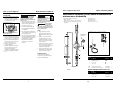
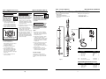
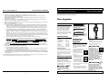
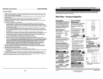
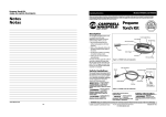
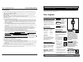
See Warranty on page 4 for important information about commercial use of this product.
Filtro • Regulador de Presión
Modelo PA212503 y KBA110
Model PA212503 and KBA110
Operating Instructions & Parts Manual
Garantía Limitada
1
2.
DURACION: A partir de la fecha de compra por el comprador original tal como se especifica a continuación: Un año.
QUIEN OTORGA ESTA GARANTIA (EL GARANTE: Campbell Hausfeld / The Scott Fetzer Company 100 Production Drive,
Harrison, Ohio 45030 Teléfono: (800) 543-6400
3. QUIEN RECIBE ESTA GARANTIA (EL COMPRADOR): El comprador original (que no sea un revendedor) del producto
Campbell Hausfeld.
4. PRODUCTOS CUBIERTOS POR ESTA GARANTIA: Cualquier clavadora, grapadora, herramienta neumática, pistola
pulverizadora, inflador o accesorio neumático suministrado o fabricado por el Garante.
5. COBERTURA DE LA GARANTIA: Los defectos substanciales de material y fabricación que ocurran dentro del período de
validez de la garantía.
6. LO QUE NO ESTA CUBIERTO POR ESTA GARANTIA:
A. Las garantías implícitas, incluyendo aquellas de comercialidad E IDONEIDAD PARA FINES PARTICULARES, ESTAN
LIMITADOS A LO ESPECIFICADO EN EL PARRAFO DE DURACION. Si este producto es empleado para uso comercial,
industrial o para renta, la garantía será aplicable por noventa (90) días a partir de la fecha de compra. En algunos
estados no se permiten limitaciones a la duración de las garantías implícitas, por lo tanto, en tales casos esta
limitación no es aplicable.
B. CUALQUIER PERDIDA DAÑO INCIDENTAL, INDIRECTO O CONSECUENTE QUE PUEDA RESULTAR DE UN DEFECTO,
FALLA O MALFUNCIONAMIENTO DEL PRODUCTO CAMPBELL HAUSFELD. En algunos estados no se permite la
exclusión o limitación de daños incidentales o consecuentes, por lo tanto, en tales casos esta limitación o exclusión
no es aplicable
C. Cualquier falla que resulte de un accidente, abuso, negligencia o incumplimiento de las instrucciones de
funcionamiento y uso indicadas en el (los) manual(es) que se adjunta(n) al producto. Dichos accidentes, abusos por
parte del comprador, o falta de operar el producto siguiendo las instrucciones del manual de instrucciones
suministrado también debe incluir la desconexión o modificación de los instrumentos de seguridad. Si dichos
instrumentos de seguridad son desconectados, la garantía quedaría cancelada.
D. Los ajustes normales explicados en el(los) manual(es) suministrado(s) con el producto.
E. Artículos o servicios normalmente requeridos para el mantenimiento del producto, tales como: anillos en O,
resortes, amortiguadores, defensas, hojas de impulsor, fusibles, baterías, empaques, almohadillas o sellos, boquillas
de fluído, agujas, boquillas para rociar arena, lubricantes, mangueras de material, elementos filtrantes, álabes de
motores, abrasivos, hojillas, discos para cortar, cinceles, retenes para cinceles, cortadores, collarines, mandriles,
mordazas para remachadoras, brocas para desarmadores, almohadillas para lijar, soportes de almohadillas,
mecanismo de impacto o cualquier otro artículo desgastable que no se haya enumerado específicamente. Estos
artículos sólo estarán cubiertos bajo esta garantía por noventa (90) días a partir de la fecha de compra original. Los
artículos subrayados sólo están garantizados por defectos de material o fabricación.
7. RESPONSABILIDADES DEL GARANTE BAJO ESTA GARANTIA: Reparar o reemplazar, como lo decida el Garante, los
productos o componentes que estén defectuosos, se hayan dañado o hayan dejado de funcionar adecuadamente,
durante el período de validez de la garantía
8. RESPONSABILIDADES DEL COMPRADOR BAJO ESTA GARANTIA:
A. Suministrar prueba fechada de compra y la historia de mantenimiento del producto.
B. Entregar o enviar el producto o componente Campbell Hausfeld al Centro de Servicio autorizado Campbell Hausfeld
más cercano. Los gastos de flete, de haberlos, deben ser pagados por el comprador.
C. Seguir las instrucciones sobre operación y mantenimiento del producto, tal como se indica(n) en el (los) manual(es)
del propietario
9. CUANDO EFECTUARA EL GARANTE LA REPARACION O REEMPLAZO CUBIERTO BAJO ESTA GARANTIA: La reparación o
reemplazo dependerá del flujo normal de trabajo del centro de servicio y de la disponibilidad de repuestos.
Esta garantía limitada es válida sólo en los EE.UU., Canadá y México y otorga derechos legales específicos. Usted también
puede tener otros derechos que varían de un Estado a otro. o de un país a otro.
Please read and save these instructions. Read carefully before attempting to assemble, install, operate or maintain the product described.
Protect yourself and others by observing all safety information. Failure to comply with instructions could result in personal injury and/or
property damage! Retain instructions for future reference.
Filter - Regulator
Description
The filter/regulator combines a general
purpose filter with a pressure regulator
in one compact unit. The filter is
designed to remove most liquid and
solid particles from the air supply. The
self-relieving pressure regulator is used
to adjust the outlet pressure between
0 - 150 psi.
Specifications
Regulator
Self
style . . . . . . . . . . . . . . .relieving
Max. Temperature . . .150˚ F
Max. Pressure . . . . . . .150 psi
Air Inlet/outlet . . . . . .3/8” NPT
Gauge Ports . . . . . . . . .1/8” NPT
Filter Element . . . . . . .5 microns
Unpacking
Warning indicates
a potentially
hazardous situation which, if not
avoided, could result in death or
serious injury.
! WARNING
Caution indicates a
!
potentially
hazardous situation which, if not
avoided, may result in minor or
moderate injury.
CAUTION
Notice indicates
important
information, that if not followed, may
cause damage to equipment.
NOTICE
Figure 1
General Safety
Information
!
This product is a part of a high pressure
system and the following safety
precautions must be followed at all
times along with any other existing
safety rules.
After unpacking the unit, inspect
carefully for any damage that may have
occurred during transit. Make sure to
tighten fittings, bolts, etc., before
putting unit into service.
Read this instruction manual
before installing this device
to the air supply system. Be
thoroughly familiar with
the controls and the proper use of the
equipment.
Safety Guidelines
1. Safety glasses must be
worn during operation.
Always work in a well
ventilated area.
This manual contains information that
is very important to know and understand. This information is provided for
SAFETY and to PREVENT EQUIPMENT
PROBLEMS. To help recognize this
information, observe the following
symbols.
Danger indicates
an imminently
hazardous situation which, if not
avoided, will result in death or serious
injury.
!
DANGER
MANUAL
2. Do not exceed any pressure rating
of any component in the system.
3. Protect air lines from damage
and/or punctures.
4. Check air hoses for weak or worn
condition before each use. Make
sure all connections are secure.
5. Keep all nuts, bolts and screws tight
and ensure equipment is in safe
working condition.
DANGER
This product is specifically
designed for compressed air
service ONLY. Use with any other
material (liquid or gas) is a
misapplication and not permitted. Use
or injection of certain hazardous
liquids or gases in the system (such as
oxygen, alcohol or liquid petroleum
gas) will harm the unit and result in a
combustible condition or hazardous
external leakage. Misapplication will
void all warranties and manufacturer’s
responsibilities.
The relief flow
capacity of
regulators is limited. Install additional
pressure relief devices to alleviate over
pressurized conditions. Written
approval must be obtained from
manufacturer if this device is to be
used for life support systems or other
non-industrial applications.
!
DANGER
Installation
! WARNING
Disconnect power and
release all pressure from the
system before attempting to
install, service, relocate or perform any
maintenance.
REMINDER: Keep your dated proof of purchase for warranty purposes! Attach it to this manual or file it for safekeeping.
© 2006
For parts, product & service information
visit www.chpower.com
IN708202AV 4/06
Flow direction arrow
knob is unlocked when adjusting
pressure. The regulator will be
damaged if the knob is turned in the
locked position.
1. Before pressurizing system, make
certain the bowl is securely locked
in place by hand tightening the
bowl ring until it is snug.
2. Unlock the regulator adjusting
knob by pulling knob away from
the regulator.
Figure 2 Detail showing location of
flow direction arrow
2. Remove plugs from plastic bag. Use
PTFE tape on the threads and install
securely in the ports. (See Figure 3.)
4. Turn on the air pressure supply and
turn the adjusting knob clockwise
until the desired outlet pressure is
reached. Push the regulator
adjusting knob toward the
regulator to lock in desired
pressure.
! WARNING
Release all pressure before
attempting to install, service,
relocate or perform any
maintenance on the air system.
Personal injury and/or property
damage could occur.
Para ordenar repuestos, sírvase llamar al concesionario
más cercano a su domicilio
Puede escribirnos a:
Sirvase darnos la siguiente información:
- Número del modelo
- Número de Serie o código con fecha (de haberlo)
- Descripción y número del repuesto según la lista
de repuestos
Attn: Customer Service
100 Production Drive
Harrison, OH 45030 U.S.A.
Always depress!
urize the unit
before removing the bowl. Personal
injury and/or property damage could
occur. If bowl is difficult to remove, it
may be under pressure.
WARNING
FILTER
Ménsulas de montaje (se venden por separado)
1. Inspect and replace cracked,
damaged or deteriorated seals.
Wipe bowls with a soft, dry cloth to
clean.
5 (Vendido por
separado)
2. Replace or clean filter element
periodically. Remove the filter
element and tap filter on a hard
surface or use an air gun to blow
out residual dirt.
7
80
10
0
60
4
6
120
3. Securely mount the filter /regulator
in a vertical position as close as possible to air tool connection.
4. Verify the arrow points to the
outlet. (See Figure 2.)
5. Install the unit with the same pipe
size as the piping in use. Avoid
using unnecessary fittings,
couplings, etc., that restrict airflow.
6. Connect the air supply to the inlet
port.
3. Turn the regulator adjusting knob
counterclockwise until no load is on
the regulating spring.
Maintenance
8
2
140
1. Locate the air flow direction arrow
(See Figure 2, detail). This arrow
shows the direction of the air flow,
i.e., it points to the outlet.
Operation
Ensure the reguNOTICE lator adjusting
Modelo PA212503 y KBA110
40
(Continued)
Filtro • Regulador de Presión
20
Installation
Model PA212503 and KBA110
10
11
0
0
Filter • Pressure Regulator
BAR
100xkPa
psi
0
16
3. Drain bowls at least once per work
shift. To avoid spray or splatter,
cover bottom of filter with a cloth
and turn the manual drain.
6
4. Before placing the unit in service,
make sure the bowl is reinstalled
and securely locked in place.
1
3
Technical Service
4
For information regarding the
operation or repair of this product,
please call 1-800-543-6400.
Lista de Repuestos
2
Figura 3
No. de
Ref.
Descripción
Repuesto
1
2
3
Tapón NPT de 1/8”
Elemento del filtro
Bowl o-ring
ST022400AV
1
1
1
4
Filter o-ring
1
Kit del elemento del filtro
SX139400AV
1
Elementos de repuesto del filtro
SX139500AV
2
Optional Replacement Parts List
No. de
Descripción
Repuesto
5
6
Medidor
Modular Bracket
HF007600AV
SX139600AV
1
1
7
Wall Bracket
SX139700AV
1
Ref.
www.chpower.com
2
Ctd.
7 Sp
Ctd.
Desconecte la unidad y
libere toda la presión del
sistema antes de tratar de
instalar, darle servicio,
reubicar o darle cualquier
tipo de mantenimiento.
1. Ubique la flecha de dirección de
flujo (Vea Figura 2). Esta flecha
muestra la dirección del flujo de
aire, o sea, apunta hacia la salida.
2. Retire los tapones de la bolsa de
plástico. Aplique cinta PTFE en las
La flecha de dirección de flujo
1. Antes de presurizar el sistema,
asegúrese de que el envase quede
firmemente asegurado en su lugar
ajustando el anillo del envase hasta
que quede apretado.
2. Para quitarle el seguro a la perilla del
regulador, hale la perilla.
3. Gire la perilla del regulador en
sentido contrario a las agujas del
reloj hasta que el resorte esté
completamente estirado (sin presión)
4. Encienda la fuente de suministro de
aire y gire la perilla en el mismo
sentido de las agujas del reloj hasta
alcanzar la presión deseada. Oprima
la perilla hacia regulador para fijarla
a la presión deseada.
roscas e instálelos firmemente en
los orificios (Vea Fig. 3).
3. Instale adecuadamente el
filtro/regulador en posición vertical
lo más cerca posible de la
herramienta neumática.
4. Verifique que la flecha apunte
hacia la salida (Vea Fig. 2).
5. Instale la unidad con tuberías del
mismo tamaño de las usadas. Evite
usar conectores, acopladores, etc
adicionales que pudiesen restringir el
flujo de aire.
6. Conecte el suministro de aire al
orificio de entrada.
Libere toda la presión del
sistema antes de tratar de
instalar, darle servicio, reubicar
o darle cualquier tipo de mantenimiento
al sistema de aire. De no hacerlo podría
ocasionarle heridas personales o daños a
su propiedad.
For Replacement Parts, call 1-800-543-6400
Please provide following information:
- Model number
- Serial Number (if applicable)
- Part description and number as shown
in parts list
Siempre
!
libere
toda la presión de la unidad antes de
desconectar el envase. De no hacerlo
podría ocasionarle heridas personales o
daños a su propiedad. Si tiene dificultad
para desconectar el envase, éste podría
estar bajo presión.
Address parts correspondence to:
Attn: Customer Service
100 Production Drive
Harrison, Ohio 45030 U.S.A.
ADVERTENCIA
Mounting Brackets (Sold Separately)
5 (Sold Separately)
FILTRO
1. Inspeccione los sellos y reemplace
aquellos que estén rotos, dañados o
deteriorados. Limpie los envases con
un trapo suave y seco.
80
10
4
6
8
2
10
11
0
BAR
100xkPa
psi
2. Periódicamente reemplace o limpie
el elemento del filtro. Saque el
elemento del filtro y golpéelo contra
una superficie dura o use una pistola
neumática para eliminar los residuos
de impurezas.
7
0
60
120
Figura 2 Detalle mostrando ubicación
de la flecha de dirección de flujo
AVISO
Mantenimiento
! ADVERTENCIA
140
ADVERTENCIA
Cerciórese de
que la perilla para ajustar el regulador
no tenga el seguro cuando vaya a
ajustar la presión. Si gira la perilla con
el seguro puesto, dañará el regulador.
Model PA212503 and KBA110
40
!
Funcionamiento
Filter • Pressure Regulator
20
Instalación
Modelo PA212503 y KBA110
0
Filtro • Regulador de Presión
0
16
6
1
3. Drene los envases por lo menos una
vez durante un turno de trabajo.
Para evitar salpicaduras, cubra el
fondo del filtro con un trapo y gire el
drenaje manual.
3
4. Antes de comenzar a utilizar la
unidad, cerciórese de que el envase
esté bien instalado y asegurado.
2
4
Replacement Parts List
Ref.
No.
Servicio Técnico
Para mayor información sobre el
funcionamiento o reparación de este
producto, comuníquese al 1-800-5436400.
Figure 3
Description
Part
Number
1
2
3
1/8” NPT Plug
Filter element
Bowl o-ring
ST022400AV
1
1
1
4
Filter o-ring
1
Filter element kit
SX139400AV
1
Replacement filter elements
SX139500AV
2
Qty.
Optional Replacement Parts List
Ref.
No.
Description
Part
Number
5
6
Gauge, 1/8” NPT
Modular Bracket
HF007600AV
SX139600AV
1
1
7
Wall Bracket
SX139700AV
1
Qty.
www.chpower.com
6 Sp
3
Ver la Garantía en página 8 para información importante sobre el uso comercial de este producto.
Filter • Pressure Regulator
Model PA212503 and KBA110
Modelo PA212503 y KBA110
Manual de Instrucciones y Lista de Repuestos
Limited Warranty
1.
2.
DURATION: From the date of purchase by the original purchaser as follows: One Year.
WHO GIVES THIS WARRANTY (WARRANTOR): Campbell Hausfeld / Scott Fetzer Company, 100 Production Drive,
Harrison, Ohio, 45030, Telephone: (800) 543-6400
3. WHO RECEIVES THIS WARRANTY (PURCHASER): The original purchaser (other than for purposes of resale) of the
Campbell Hausfeld product.
4. WHAT PRODUCTS ARE COVERED BY THIS WARRANTY: Any Campbell Hausfeld nailer, stapler, air tool, spray gun,
inflator or air accessory supplied or manufactured by Warrantor.
5. WHAT IS COVERED UNDER THIS WARRANTY: Substantial defects in material and workmanship which occur within the
duration of the warranty period.
6. WHAT IS NOT COVERED UNDER THIS WARRANTY:
A. Implied warranties, including those of merchantability and FITNESS FOR A PARTICULAR PURPOSE ARE LIMITED
FROM THE DATE OF ORIGINAL PURCHASE AS STATED IN THE DURATION. If this product is used for commercial,
industrial or rental purposes, the warranty will apply for ninety (90) days from the date of purchase. Some States
do not allow limitation on how long an implied warranty lasts, so the above limitations may not apply to you.
B. ANY INCIDENTAL, INDIRECT, OR CONSEQUENTIAL LOSS, DAMAGE, OR EXPENSE THAT MAY RESULT FROM ANY
DEFECT, FAILURE, OR MALFUNCTION OF THE CAMPBELL HAUSFELD PRODUCT. Some States do not allow the
exclusion or limitation of incidental or consequential damages, so the above limitation or exclusion may not apply
to you.
C. Any failure that results from an accident, purchaser’s abuse, neglect or failure to operate products in accordance
with instructions provided in the owner’s manual(s) supplied with product. Accident, purchaser's abuse, neglect or
failure to operate products in accordance with instructions shall also include the removal or alteration of any safety
devices. If such safety devices are removed or altered, this warranty is void.
D. Normal adjustments which are explained in the owner’s manual(s) provided with the product.
E. Items or service that are normally required to maintain the product, i.e. o-rings, springs, bumpers, debris shields,
driver blades, fuses, batteries, gaskets, packings or seals, fluid nozzles, needles, sandblast nozzles, lubricants,
material hoses, filter elements, motor vanes, abrasives, blades, cut-off wheels, chisels, chisel retainers, cutters,
collets, chucks, rivet jaws, screw driver bits, sanding pads, back-up pads, impact mechanism, or any other
expendable part not specifically listed. These items will only be covered for ninety (90) days from date of original
purchase. Underlined items are warranted for defects in material and workmanship only.
7. RESPONSIBILITIES OF WARRANTOR UNDER THIS WARRANTY: Repair or replace, at Warrantor’s option, products or
components which are defective, have malfunctioned and/or failed to conform within duration of the warranty period.
8. RESPONSIBILITIES OF PURCHASER UNDER THIS WARRANTY:
A. Provide dated proof of purchase and maintenance records.
B. Deliver or ship the Campbell Hausfeld product or component to the nearest Campbell Hausfeld Authorized Service
Center. Freight costs, if any, must be borne by the purchaser.
C. Use reasonable care in the operation and maintenance of the products as described in the owner’s manual(s).
9. WHEN WARRANTOR WILL PERFORM REPAIR OR REPLACEMENT UNDER THIS WARRANTY: Repair or replacement will be
scheduled and serviced according to the normal work flow at the servicing location, and depending on the availability
of replacement parts.
This Limited Warranty applies in the United States, Canada and Mexico only and gives you specific legal rights. You may
also have other rights which vary from state to state or country to country.
Sírvase leer y guardar estas instrucciones.Lea con cuidado antes de tratar de armar, instalar, manejar o darle servicio al producto descrito en
este manual. Protéjase Ud. y a los demás observando todas las reglas de seguridad. El no seguir las instrucciones podría resultar en heridas y/o
daños a su propiedad. Guarde este manual como referencia.
Filtro - Regulador
Descripción
El filtro/regulador combina un filtro
para uso general con un regulador de
presión en una unidad compacta. El
filtro está diseñado para quitar la
mayoría de las partículas líquidas y
sólidas del suministro de aire. El
regulador automático de liberación de
presión se utiliza para ajustar la salida
de presión entre 0 y 150 psi.
Especificaciones
Tipo de
Alivio
Regulador . . . . . . . . . .Automático
Temperatura Máx . . .66˚ C
Presión Máx . . . . . . . .10,34 bar
Entrada/Salida
9,53 mm
de aire . . . . . . . . . . . . .(3/8”) NPT
Puertos del
3,18 mm
manómetro . . . . . . . . .(1/8”) NPT
Elemento filtrante . . .5 micrones
Para Desempacar
Al desempacar este producto, revíselo
con cuidado para cerciorarse de que
esté en perfecto estado. Cericiórese de
apretar todas las conexiones, pernos,
etc. antes de comenzar a utilizar la
unidad.
Medidas de Seguridad
Este manual contiene información que
es muy importante que sepa y
comprenda. Esta información se la
suministramos como medida de
SEGURIDAD y para EVITAR PROBLEMAS
CON EL EQUIPO. Debe reconocer los
siguientes símbolos.
Ésto le
!
indica
que hay una situación de peligro
inmediato, que si no la evita, le
ocasionará la muerte o heridas de
gravedad.
PELIGRO
!
ADVERTENCIA
Ésto le
indica
que hay una situación, que si no la
evita, podría ocasionará la muerte o
heridas de gravedad.
Ésto le
indica
que hay una situación que podría
ocasionarle heridas no muy graves.
!
PRECAUCION
AVISO
Ésto le
indica una información importante, que
de no seguirla, le podría ocasionará
daños al equipo.
Figura 1
Informaciones
Generales de
Seguridad
todas las condiciones estén bien
apretadas.
Este producto es parte de un sistema de
alta presión y siempre debe seguir las
siguientes medidas de seguridad al
igual que otras medidas de seguridad
establecidas.
Lea este manual de instrucciones antes
de instalar esta unidad en el
sistema de suministro de
aire. Familiarícese con los
controles y el uso adecuado
del equipo.
MANUAL
1. Siempre debe usar anteojos de
seguridad para operar la
unidad. Siempre trabaje
en áreas bien ventiladas.
2. No exceda la presión
indicada para ninguno de los
componentes del sistema.
3. Proteja todas las líneas de aire contra
daños o rupturas.
4. Chequée las mangueras de aire a ver
si están debilitadas o desgastadas
antes de cada uso. Cerciórese de que
5. Mantenga todas las tuercas, pernos y
tornillos bien apretados y cerciórese
de que el equipo esté en buenas
condiciones funcionar.
!
PELIGRO
Este producto está diseñado
específicamente para
sistemas de aire comprimido
SOLAMENTE. El usarlo con
otros materiales (líquidos o gases) no
es adecuado y no está permitido. El uso
o la inyección de ciertos líquidos o
gases peligrosos en el sistema (tales
como oxigeno, alcohol o gas líquido de
petroleo) dañará la unidad y
ocasionará una condición combustible
o fuga externa peligrosa. El uso
inadecuado cancelará todas las
garantías y responsabilidades civiles
del fabricante.
La capacidad de
flujo de los reguladores es limitada.
Instale artefactos adicionales para
liberar la presión para evitar
condiciones de presiones excesivas.
Debe obtener permiso por escrito del
fabricante si piensa utilizar esta unidad
en sistemas médicos u otros usos no
industriales.
!
PELIGRO
RECORDATORIO: ¡Guarde su comprobante de compra con fecha para fines de la garantía!
Adjúntela a este manual o archívela en lugar seguro.
www.chpower.com
4
© 2006
IN708202AV 4/06