1
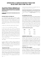
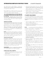
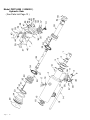
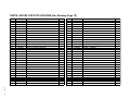
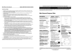
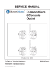
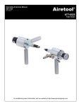
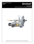
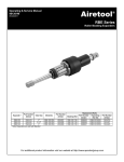
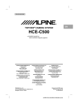
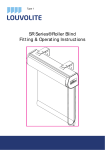
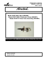
OPERATING & SERVICE
MANUAL # 90113-IM
REV 11/29/00
Airetool
®
Model PATP 9000 Ram (5524902)
Model PATP 9400 P Hydraulic Pump (2999307)
Model PATP HT Hose Tube Assembly (5524903)
READ SAFETY RECOMMENDATIONS BEFORE OPERATING THIS TOOL
AIRETOOL OPERATION
302 South Center Street
Springfield, Ohio 45506
Page - 1
Safety Recommendations
WARNING: FOR YOUR SAFETY AND THE SAFETY OF
OTHERS, READ AND UNDERSTAND THE SAFETY RECOMMENDATIONS AND OPERATING INSTRUCTIONS BEFORE USING THIS TOOL.
1.
KNOW YOUR POWER TOOL – Read your operating
and service manual carefully. Learn its applications and limitations as well as the specific potential hazards particular to this tool.
2.
DISCONNECT TOOLS – when not in use, before servicing, when changing accessories such as grippers and draw rods, etc.
3.
AVOID AGAINST ACCIDENTAL STARTING – Do not
carry the tool with your finger on the switch. Be
sure the shut off valve is in the off position before
connecting the air supply to this tool.
4.
KEEP HANDS AWAY FROM ALL MOVING PARTS.
5.
STAY ALERT – Watch what you are doing and use
common sense.
6.
ALWAYS WEAR PROTECTIVE EQUIPMENT:
For additional information on eye and face protection, refer
to Federal OSHA Regulations, 29 Code of federal regulations, Section 1910.133 eye and Face Protection, and American National Standards Institute, ANSI A87.1, Occupational
and Educational Eye and Face Protection Z87.1 is available
from the American National Standards Institute, 1430 Broadway Avenue, New York, NY 10018.
Page - 2
Hearing protectors are required in high noise areas, 85dBA or greater.
The operation of tools and equipment in the area, reflective surfaces,
process noises and non-resonant structures can substantially contribute to and increase the noise level in the area. For additional information on hearing protection, refer to Federal OSHA Regulations section 1910.95 Occupational Noise Exposure, and the American National
Standards Institute, ANSI S12.6 Hearing Protectors.
Some individuals are susceptible to disorders of the hands
and arms when exposed to task which involve highly repetitive motions or vibration. Those individuals predisposed to
vasculatory or circulation problems may be particularly susceptible. Cumulative trauma disorders such as carpal tunnel syndrome and tendonitis can be caused by repetitions,
forceful exertions of the hands and arms. These disorders
develop gradually over periods of weeks, months, and years.
•
Tasks should be performed in such a manner that the
wrists are maintained in a neutral position which is not
flexed, hyperextended, or turned side to side.
•
Stressful postures should be avoided and can be
controlled through tool selection and work location.
Any user suffering from prolonged symptoms of tingling,
numbness, clumsiness or weakened grip, nocturnal pain in
the hand or any other disorder of the shoulders, arms, wrists,
or fingers is advised to consult with a physician. If it is
determined that the symptoms are job related or aggravated
by movements and postures dictated by the job design it
may be necessary for the employer to take steps to prevent
further occurrences. These steps might include, but are not
limited to repositioning the workpiece or redesigning the work
station, reassigning workers to other jobs, rotating jobs, altering work pace, and / or changing the type of tool used so
as to minimize stress on the operator. Some task may
require more than one type of tool to obtain the optimum
operator/tool/task relationship.
The following recommendations will help reduce or moderate the effects of repetitive work motions and/or extended
vibration exposure.
·
Use a minimum hand grip force consistent with proper
control and safe operation.
·
Keep wrist as straight as possible.
·
Keep body and hands warm and dry.
·
Avoid anything that inhibits blood circulation
- Smoking tobacco
- Cold temperatures
- Certain drugs
·
Avoid highly repetitive movements of hands and wrist,
and continuous vibration exposure.
Follow good machine shop practices. Rotating shafts
and moving components can entangle and entrap, and
can result in serious injuries. Never wear long hair,
loose fitting clothes, gloves, ties, or jewelry when working with or near the equipment.
Use of this tool may produce hazardous fumes, particles
and/or dust form the tube or vessel they are being extracted
from. To avoid adverse health effects utilize adequate ventilation and/or a respirator. Read the material safety data
sheet of any fluids or other materials involved in the tube
removal process.
Page - 3
Model PATP 9400 Ram (5524902)
T O O L S P E C I F I C A T I O N S:
Maximum Operating Pressure - 10,000 PSI (650 Bar)
Pulling Capacity @ 10,000 PSI (690 Bar) - 13 3/4 Tons (12.5 Metric Tons)
Pulling Stroke - 2-3/8” (60 mm)
Length - 23 3/8” (594 mm)
Side to Center Distance - 3 5/8” (92.1 mm)Approx
Tube Pulling Capacity - 5/8” thru 1” OD (16 thru 25 mm)
United States
European Office
Cooper Power Tools
Airetool Operation
302 South Center Street
Springfield, Ohio 45506
Phone: 937/323-4981 – Fax: 937/323-6524
Intercontinental U.S. Fax: 1-800/375-8906
Cooper Power Tools B.V.
P O BOX 522
2900 AM Capelle –A/D Ijssel
The Netherlands
Phone: 31-10-4588722 – Fax 31-10-4587173
Telex: INBV NL
Page - 4
Model PATP-9000
Hydraulic Tube Puller
1.
4.
2.
3.
Tube Pulling System Complete
Consists Of :
1.
2.
3.
4.
PATP 9000
PATP 9400 P
PATP HT
ATP 9022 XXX
Ram Assembly
Hydraulic Pump Unit
Hose-Tube Assembly
Gripper Kit ( XXX See Chart On
5524902
2999307
5524903
Page 14 )
Page - 5
OPERATING & SERVICE INSTRUCTIONS FOR
Model PATP-9000 TUBE PULLER
THIS SYSTEM IS CAPABLE OF GENERATING 13 3/4
TONS OF FORCE AT 10,000 PSI, THEREFORE, DO NOT
OPERATE THIS SYSTEM BEFORE FULLY READING
AND UNDERSTANDING THE SET-UP AND OPERATING
INSTRUCTIONS.
ALWAYS WEAR EYE PROTECTION WHEN USING THIS
EQUIPMENT.
BEFORE STARTING THE PUMP UNIT
1) To avoid possible serious injury to personnel or equipment, always post DANGER SIGNS (Part. No. 2987064)
and insure that the area directly behind the tube sheet/
bundle is kept clear and that a suitable barrier is in use
while using the puller. If a draw rod should break while pulling tube stubs or tubes, the draw rod tip, cam and expansion nut can be propelled out into this area with considerable force.
2) Make sure the vented filler cap/fill gauge is installed.
rolled section be measured with an AIRETOOL Tube Gage.
See Gripper Selection chart on Page 14.
DRAW ROD-EXPANSION NUT- LOCK NUT SELECTION:
These three components must match the gripper chosen
(if necessary a second expansion nut may be used instead of a lock nut). See Gripper Selection chart on Page
14.
NOSE BUSHING SELECTION:
The bushing ID must be large enough to clear the tube OD
(including flared or belled ends), and the bushing OD must
be small enough so that it does not interfere with adjacent
tubes protruding from the tube sheet. Standard nose bushings accommodate tubes that have not been flared or belled.
NOTE: It may be necessary in some applications where
the tubes are brittle and/or if the grippers are positioned
over tube sheet serrations (grooves), to shorten the nose
bushing to allow the grippers to seat further into the tube
sheet. Care must be taken that the cut be smooth and
square to avoid gripper breakage. Since the bushing is casehardened, a lathe with carbide tooling is recommended.
3) Check oil level (see pump manual # 90120-IM).
Standard Nose Bushing sizes:
4) Check hose for leaks, cuts, abrasions or bulges—read
and fully understand the warning tags attached to the hose
assemblies. Check hose’s label and fittings for underrated
replacement parts. NEVER operate with damaged hoses
and/or cords. NEVER allow hoses and/or cords to kink or
knot. NEVER place hoses in an area where they may be
stepped on or run over by any type of vehicle, cart, hand
truck, etc. NEVER connect any hydraulic fitting, hose or
device to the hydraulic portion of the pump that does not
carry a 10,000 psi rating.
5) Make sure all hose and control tube connections are
fully coupled.
6) Check air supply for sufficient capacity (see pump unit
nameplate). Note: A ½” ID x 10’ long supply hose is recommended. If a longer hose is required, ¾” ID or larger will
provide best performance. The use of quick disconnects
will decrease performance unless they are sufficiently oversized or of an unrestricted flow type.
GRIPPER SELECTION:
Grippers are sized for nominal ID/OD brass tubes rolled
with normal wall reduction in tube sheet holes with normal
clearance. Tubes with smaller than normal rolled ID’s may
require the use of a smaller gripper for smooth release of
the tube after pulling. Tubes with larger ID’s may require
the use of a larger gripper to avoid the excessive bending of
the gripper and prolong gripper life. For determining the
most suitable gripper, it is recommended that the tube’s
Page - 6
SIZE
I.D.
5/8 “
3/4“
7/8 “
1“
11/16 “
7/8“
31/32 “
1 3/16 “
O. D.
29/64 “
1 1/8 “
1 11/64 “
1 5/16 “
GRIPPER KIT INSTALLATION
Lubricate the threads of the draw rod with an anti-galling
compound, thread the draw rod into the piston rod and
snug with a wrench. Thread proper size gripper adapter (2)
into the outside piston. With the two O-rings in place, slide
the gripper complete (3 segments) over the draw rod such
that the segments are aligned and spaced by the adapter
lugs and retained with the proper sized gripper retainer (1)
tightened securely. Lubricate the cam and thread the cam
and lock nut onto the end of the draw rod until the cam
contacts but does not expand the gripper—see Gripper
Adjustment below.
SETTING UP THE EQUIPMENT
Connect the pump to an adequate air supply with appropriate hoses. Inadequate air supply can cause poor pump
performance and prevent the pulling of some tubes. Make
sure that the work area is arranged to provide adequate
room for movement and protection of the supply and operation hoses. Make sure that the vented filler cap/level indicator is installed on the pump (see pump manual #90120-
OPERATING/SERVICE INSTRUCTIONS
IM). Connect the hose /tube assembly to the pump and
tube puller assembly. Hydraulic connections push together
until they snap. Control tube connections should be properly keyed and threaded securely.
When the pump motor is started, the ram will (if not fully
forward) move to the full reset position, build enough pressure to trip an internal unloader, and then idle.
FULL SYSTEM PRESSURIZING OF THE RETURN HOSE
AT THE RESET POSITION INDICATES A MALFUNCTION
OF THE PUMP - immediately stop the motor by pushing
the red button on the pump and/turning of the air shut-off
valve and clear the malfunction before proceeding. Cycle
the puller assembly several times to warm the system before setting the gripper.
GRIPPER ADJUSTMENT
Pull the trigger until the gripper starts to move (the draw
rod moves about 3/8" first) to put the puller in the grippersetting position. Turn the motor off (by pushing the red
MOTOR STOP button on the pump) and measure the diameter of the back tooth. If it is not at least .020" larger
than the ID of the tube to be pulled, adjust the expansion
nut in until it is. Make sure that the correct gripper size is
being used since over-expansion of an undersized gripper
will decrease gripper life.
NOTE: Very hard tubes cannot be pulled in a conventional
manner with this tool since the gripper teeth will slide instead of gripping into the surface of the tube. Tighten the
lock nut against the expansion nut and confirm that the
draw rod is tight. Install the nose bushing and lock it in
place with one of the set screws.
SERVICE INSTRUCTIONS
Most hydraulic cylinders give relatively long life and good
dependability when they are used within their design parameters. The use of approved clean hydraulic fluid is essential if good seal life is to be expected (see pump manual
#90120-IM). It is also essential that care be taken when
coupling the hoses to the cylinder and pump to avoid getting dirt or other contamination into the system where it
could abrade the seals and cause them to leak.
DISASSEMBLY (Refer to the exploded view drawing on
the following page for the item numbers referenced.) Note:
All threaded components have right-hand threads.
HANDLE/ LIMIT SWITCH REMOVAL
1. Clamp the puller upside down in a soft jaw vise so that
the puller is securely held with the hydraulic connections pointed up.
2. Remove switch cover screws (6) and cover (8).
3. Remove the limit valve mounting screws (10 ).
-continued-
4. Remove the handle mounting screw (41). Loosen the
handle mounting set screws (38), and remove the handle
assembly, tubing conduit (14) and limit valve (11) assembly, taking care not to damage the tubes when
pulling them through the slot in the switch box.
5. Inspect the valve roller and arm for free operation and
clean if necessary, or replace if damaged.
6. Carefully inspect the handle tubing for deterioration,
damage or loose connections and replace if required.
CYLINDER DISASSEMBLY
It is strongly recommended that PATP cylinders be returned
to Airetool for repairs involving removal of the cylinder plug.
The following instructions are provided for use only by knowledgeable service personnel using appropriate facilities and
equipment.
1. Remove the gripper retainer (1), gripper, draw rod, nose
bushing, and gripper adapter (2).
2. Unscrew the nose bushing adapter (3).
3. Thoroughly clean all exposed surfaces of the puller with
a suitable solvent and blow dry.
NOTE:
All further operations must be performed in a
thoroughly clean environment to avoid premature failure of
the puller or pumping unit due to contamination.
4. Remove the hydraulic couplings (12 and 13) and drain
out as much of the hydraulic fluid as possible.
5. Securely attach a heavy steel bar to the ¼-20 threaded
holes in the cylinder plug with three grade 8 cap screws
and loosen the plug. The cylinder must be held securely toward the nose end of the cylinder and with the
torque reacted against the suspension eye boss and
not the hose connections.
6. Remove the cylinder plug and any hydraulic fluid remaining in the cylinder. Inspect the O-ring (33) and replace if cut or worn.
7. Using a suitable drift to avoid damaging the rod threads,
carefully press the piston assembly out of the case.
Take care to catch the oil remaining below the piston
assembly.
8. Pull the piston (29) assembly out of the outside piston
(20) assembly.
9. Inspect the rod seal (25) and piston seals (24) for cuts
or wear, but do not attempt to remove them unless replacement is intended. To remove a rod or piston seal,
pull the seal away from the piston (or rod) and very carefully cut through the seal with a very sharp, thin blade,
taking care to avoid scratching the piston or rod.
10. The valve plunger (30) and spring (31) can be removed
from the piston (29) after unscrewing the set screw (32).
11. The valve seat (23) can be unscrewed from the outside
piston (20) to remove the ball (22) and spring (21). The
spring should be approximately 1 1/8” long. If it has
Page - 7
OPERATING/SERVICE INSTRUCTIONS
deformed, replace it. Carefully inspect the ball and valve
seat and replace if damaged.
12. The cylinder seal (15) can be removed from the cylinder
case after removing the snap ring (16) (with long snap
ring pliers).
RE-ASSEMBLY
NOTE: When assembling seals into parts or parts into seals,
always lubricate with clean hydraulic fluid, O-Lube or
petroleum jelly. Everything that comes in contact with
the hydraulic fluid must be kept clean.
1. Install the cylinder seal (15) into the case (4) oriented as
shown and retain with the snap ring (16).
2. The pin (28) is pressed into the piston (29).
3. Install rod and piston seals oriented as shown.
4. Install spring (21) ball (22) and valve seat (23) in outer
piston (20) and tighten securely.
5. The piston rod (26) is screwed into piston (29) and secured with Loctite® 242.
6. Install valve plunger (30), spring (31) and set screw (32)
in the piston (29) with the screw flush with the piston
face and secured with 242 Loctite® or equal. Allow Loctite® to set and clean thoroughly.
7. With the spacer (27) over the pin (28), slide the piston
assembly into the outside piston assembly with the pin
going into the hole in the outside piston.
8. Install o-ring (33) in groove in the cylinder plug (34) and
screw cylinder plug into case (4). Start the O-ring into
the case with a blunt instrument to avoid pinching it.
Securely tighten cylinder plug.
9. Loctite® (pipe sealant) couplings (12 &13) to case (4).
Note that the male coupler goes on the gripper end.
10. If the wiring harness has been removed, feed the trigger
switch and wiring up through the receptacle hole and
install receptacle (36) with screws (37). Feed the cord
out through the wire conduit hole.
11. If the plunger replacement is required, screw the spring
plunger (32) into the handle (40) from the front (using an
installation tool engaged in the slots in the plunger end)
so that the trigger bottoms out against the plunger body
before it hits the bottom of its cavity in the handle and
properly trips the switch when pulled fully.
12. Arrange the control tubing in the handle so that it will
stay in the cavity (under the retaining pin) and insert gasket (49) into handle (40).
13. Feed tubing and conduit into limit valve box on case (4)
and attach handle (40) to case with screw (41) making
sure that no tubes get pinched and that the handle is
aligned properly.
14. Tighten set screws (38).
15. Connect tubing to limit valve (11) as shown in connection diagram.
16. Install limit valve (11) assembly into case (4) with screws
(10) as shown – leave screws loose enough to adjust
Page - 8
-continued-
limit valve plate.
17. Connect the cylinder to a properly functioning ATP pump
and hose/tube assembly.
18. With all personnel clear of the unit, connect the air supply and turn on the main air shut-off valve.
19. Adjust the limit valve so that it does not hiss, but any
further actuation of the arm will start the hiss. Tighten
the screws and test for proper sequencing of the unit
with the trigger and proper adjustment of the limit valve.
20. Install limit switch cover (8) with screws (6).
21. Install a draw rod and check for proper cycling and check
all connections for leaks before returning unit to service.
PULLING TUBES
1. Inspect the face of the tube sheet and tube ID’s. Any
chips, dirt or scale which would prevent the nose bushing
from bearing squarely on the tube sheet or debris inside the
tube that will prevent the grippers from biting into the tube
material must be removed or the effectiveness and life of the
grippers will be greatly reduced.
2. The puller assembly will pull itself square to the tube
sheet as it starts its cycle; however holding the assembly
reasonably square first will prolong gripper and draw rod life.
Use of a suitable tool balancer or Model DAS tool positioner
is recommended for reducing operator fatigue.
3. Never attempt to pull tubes at an angle to the tube sheet
or serious injury to the operator and/or the equipment may
result. If obstructions prevent proper in-line access to the
tubes, extension assemblies are available to assist in pulling these tubes.
4. With the gripper kit installed and set, with hose/tube
assembly properly connected, pump connected to an adequate air supply and the area behind the tube sheet and/or
bundle cordoned off with warning signs displayed, turn on
the air shut-off valve. With everything clear of the grippers,
pull and hold the trigger.The ram will continue back until the
trigger is released or the limit valve is tripped at the end of
the stroke. The motor will continue to run until the red
MOTOR STOP button on the pump is pushed (or the air is
turned off).
5. Cycle the puller assembly several times to warm it up.
6. Insert the gripper into the tube to be pulled with the puller
nose bushing pushed squarely against the tube sheet. Pull
and hold the trigger.
7. After the tube pulls tight against the tube sheet, pull
back lightly on the puller. When the tube pulls free, release
the trigger and pull the stub/tube from the tube sheet as the
puller assembly is retracting. The gripper will release the
tube just before the puller resets fully. In some extreme
OPERATING/SERVICE INSTRUCTIONS
cases, the gripper teeth may stick in the tube, but can usually be released by momentarily pulling the trigger for a short
cycle outside the tube sheet.
8. If the puller assembly reaches the end of its useable
stoke, it will automatically reverse, reset and stop. The
trigger can be released at any time during the pulling portion
of the cycle to immediately reverse the ram or it can be
released without effect at any time after the puller has been
reversed by the end-of-stroke switch but it must be released
at the reset position before another cycle can be started.
The pump motor starts when the trigger is pulled the first
time, and remains running until the red MOTOR STOP
pushbutton valve on the pump is pushed.
9. If the tube does not pull free with a single pull attempt
(approx. 2-3/8" stroke), the gripper can be pushed forward
into the tube for a second pull (this may become necessary
in tube sheets thicker than the 2-3/8"). If additional pulls are
required to break the tube free, tubular spacers may be used
equal to the length of the tube protruding from the tube sheet.
10. When using spacers to make multiple pulls, care should
be taken to avoid interference with adjacent tubes.
11. If the tubes break off in short sections (rings) instead of
pulling free, the gripper teeth may need to be positioned
further into the tube sheet. This can be accomplished by
shortening the nose bushing on a lathe (Must be machined
square. Carbide tooling recommended).
DO NOT ALLOW THE GRIPPERS TO BE POSITIONED
BEHIND THE TUBE SHEET.This can result in equipment
breakage and/or injury to personnel.
NOTE:
1. The puller will pull only as long as the trigger is held.
Releasing the trigger will cause the puller to immediately
retract fully and stop.
2. The trigger must be released with the puller fully reset
before a new cycle can be started.
3. The cycle can be stopped at any point by turning the
pump off.
4. Once a cycle has been started, the motor will run until it
is turned off (red MOTOR STOP pushbutton valve on the
pump unit).
5. The draw rod should always move (about 3/8") before the
gripper moves at the beginning of a cycle and should always move (about 3/8") after the gripper stops at the end of
its cycle (or less if self adjusting has occurred).
6. The weight of the puller assembly should always be
supported by the operator, a balancer or a DAS unit and not
by the gripper. Resting the puller on the grippers can cause
the grippers and draw rod to bend and cause premature
failure.
-continued-
7. Allowing the unit to dwell at full pressure serves no purpose and can damage the equipment. Should overheating
occur, turn the motor off and let the unit cool before attempting to pull more tubes. IMPORTANT: If the unit is not operating properly, DO NOT USE IT - see Trouble Shooting section or contact authorized AIRETOOL representative to correct the problem before using the equipment.
SHUTDOWN
After using the puller in a wet, dirty or corrosive area, always clean and oil the tube puller assembly and the gripper
kit before putting the tool away or severe corrosion can occur. Removal of the gripper kit for prolonged storage is recommended. To further protect the working end of the piston,
you can retract it fully and turn the motor off before storage.
Note that you must release the trigger before releasing the
red pushbutton on the pump, or the pump motor will restart.
PRINCIPLE OF OPERATION
Oil directed to the rod end of the cylinder assembly flows
through the check valve in the outside piston (20) as long as
the ball (22) is held off its seat (23) by the valve plunger (30).
This causes the piston to retract, pulling the draw rod back
and expanding the gripper. When the piston has moved about
3/8" away from the outside piston, the ball seats, trapping
oil between the pistons and the two pistons move back as a
unit, pulling both the gripper and the draw rod with no further
expansion of gripper. When a tube is being pulled, the pressure between the pistons starts to rise as soon as the gripper starts to grip the tube, pushing the valve plunger (30)
back against its spring (32). When enough pressure has
built up to fully grip the tube, the valve plunger has been
pushed back far enough to allow the check valve in the outside piston to seal off so that expansion stops and the tube
is pulled by the gripper and not the draw rod. On the reset
stroke, the outside piston stops when it bottoms out on the
case. The oil between the pistons escapes past the ball in
the outside piston. When the piston (29) bottoms out, the
system pressure rises enough to trip the internal pump
unloader and the pump shifts back to its idle position.
Page - 9
TROUBLE SHOOTING
S E E S E R V IC E M A N U A L N U M B E R 90 1 20 -IM FO R H Y D R A U LIC P U M P M O D E L P A TP -9 40 0-P
G rip per slips ou t o f tub e
w ith out gripping
Exce ssive d ra w ro d
breaka ge
Pum p w ill not bu ild e noug h
pressu re to pull (u nder
10,000 psi)
1 ) G ripp ers w orn out (teeth
d ull) - repla ce grippers.
2 ) T urn adjusting n ut in for
m o re gripper expa nsion
3 ) C h eck tu be hard ness p uller w ill n ot pull excessively
w o rk- or ag e- harden ed tub es
4 ) C h eck valve spring (3 1)
a nd scre w (32) - re place if
d am age d or out of po sition .
Puller bottom s out and
press urize s on pu ll strok e
but reve rs es w he n trig ger is
releas ed.
1 ) C heck lim it valve - adjust
th e va lve plate so that valve
shifts only w he n on the cam .
2 ) C heck fo r p inched tub es.
Puller w ill not m ove from
the idle po sitio n.
1 ) M ake su re both e nds of the
tu bing conn ectors a nd pu lle r
h oses are prop erly conn ected
2 ) M ake su re trig ger valve is
fu nctio ning pro perly.
1 ) C h eck o perator techn ique
2 ) If brea ka ge continu es w ith
p ro per techniq ue, check th at
valve ba ll (22 ) sea ts a nd that
valve plu nger (30) m o ve s
p ro perly.
W hen first started a fte r
servic e, th e puller retracts
fully and s to ps w ith the
press ure sw itch trippe d
instea d of going into res et
(or staying in id le .).
C heck hose, pum p and p uller
cou plings.
1 ) M a ke su re ve nted filler cap
level g age is installed on
p um p.
2 ) C h eck o il le ve l (w ithin
g re en zone -se e pum p
m a nual).
3 ) C h eck a ir p re ssure w ith
p um p un der load . Air supp ly
a nd supp ly ho se m ust h ave
e noug h capacity to ru n pum p
w ith out excessive pre ssure
d ro p.
4 ) If pum p requires servicin g
see E N ER PA C lite rature for
locatio n of neare st EN ER PAC
service center .
P U M P - left is fem a le, rig ht is
m ale.
H O SES – o ne m ale and on e
fe m ale on e ach hose.
P U LLE R – m ale in front an d
fe m ale in ba ck.
- C A U T IO N D O N O T A T T E M P T T O D IS C O N N E C T O R D IS A S S E M B L E H O S E S , P U LLE R O R V A LV E W H ILE T H E Y A R E
P R E S S U R IZE D O R S E R IO U S IN JU R Y C O U LD R E S U LT. T H E U N IT C A N N O R M A LLY B E D E P R E S S U R IZE D
B Y T U R N IN G O FF O R D IS C O N N E C TIN G T H E A IR S U P P L Y . IF T H IS IS N O T E F F E C T IV E , D E P R E S S U R IZ E
B Y LE T TIN G T H E A S S E M B L E D U N IT S IT (W ITH T H E A IR D IS C O N N E C TE D ) U N T IL T H E P R E S S U R E
B L E E D S O F F . T O D E P R E S S U R IZE A D IS C O N N E C T E D C O M P O N E N T , S H R O U D T H E JO IN T A N D S L O W L Y
U N S C R E W A F IT T IN G U N T IL P R E S S U R E IS R E L IE V E D . A LW A Y S K E E P T H E F IT T IN G W E L L A W A Y F R O M
A N Y B O D Y C O N TA C T A N D W E A R E Y E P R O TE C T IO N .
Page - 10
NOTES:
Page - 11
Model PATP-9000 ( 5524902 )
Hydraulic Ram
( See Parts List Page 13 )
Page - 12
PARTS LISTING FOR PATP-9000 RAM (See Drawing Page 12)
ITEM
PART #
1
1
2
2
3
4
5
6
8
10
11
12
13
14
15
16
17
19
20
21
22
23
24
25
26
27
28
29
30
31
2991214
2991236
2991213
2991235
2991231
2991190
8010204
8010210
2999063
8010912
2999066
2995267
2995268
2991234
2991229
8010497
8564870
8010029
2991195
2991208
3227500
2991207
2991228
2991230
2991193
2991210
2991209
2991194
2991211
2991212
DESCRIPTION
ATP 9012 5/8 3/4 GRIPPER RETAINER
ATP 9033 7/8 1 GRIPPER RETAINER
ATP 9011 5/8 3/4 ADAPTER
ATP 9032 7/8 1 ADAPTER 7/8 1
ATP 9026 7/8 1 ADAPTER 7/8 1
ATP 9001 CYL CASE ASSEM
1/4 20 X 1/4 NYLOK SET SCREW
4 40 X 1/4 BUTTON HD SCREW
ATP 9029 B SWITCH COVER
8 32 X 5/16 FHCS 18 8
PATP 3 LIMIT VALVE
HDP 30 13A NIPPLE SFWY
HDP 30 14A COUPLER SFWY
ATP 9031 WIRE CONDUIT
ATP 9020 CYLINDER SEAL
5008 150 SNAP RING
1700 32 SUPPORT EYELET
5/16 18 HEX NUT
ATP 9002 OUTSIDE PISTON
ATP 9006 CHECK VALVE SPRING
1/4 STEEL BALL
ATP 9005 VALVE SEAT
ATP 9019 PISTON SEAL
ATP 9021 ROD SEAL
ATP 9004 PISTON ROD
ATP 9008 SPACER
ATP 9007 PIN
ATP 9003 PISTON
ATP 9009 VALVE PLUNGER
ATP 9010 REG VALVE SPR
REQ'D
ITEM
PART #
1
1
1
1
1
1
2
4
1
2
1
1
1
1
1
1
1
1
1
1
1
1
3
1
1
1
1
1
1
1
32
33
34
35
36
37
38
39
40
41
42
43
44
45
46
47
48
49
50
51
52
53
54
55
56
57
58
59
60
61
8010496
2983298
2983310
8010914
2999068
8010915
8010204
2983330
2991253
8010209
8010222
2983286
2983283
8010206
8010084
2999067
8010357
2983300
2999069
2999070
8010913
8010500
2999065
8009100
2999064
8010083
2999244
2999245
2999246
8007100
DESCRIPTION
5/16 24 HOLO LO HOLO LOK SET SCREW
ATS 8825 O RING
ATS 8814 CYLINDER PLUG
4 40 X 1/2 SHCS
PATP 5 ADAPTER
M4 X 10 PHMS DIN 85A
1/4 20 X 1/4 NYLOK SET SCREW
1/4 20X3/16 STROKE SPRING PLUNGER
ATP 9044 HANDLE
1/4 20 X 1 BUTTON HD SCREW
4 40 X 1/4 FLAT HD CAP SCREW
ATS 8818 TRIGGER COVER
ATS 8817 TRIGGER
1/8 X 1 DOWEL PIN
#6 LOCK WASHER
PATP 4 HANDLE VALVE
6 32 X 1/2 SOC HD CAP SCREW
ATS 8815 GASKET
PATP 6 BOX CONNECTOR
PATP 6 I CON INSERT
6 32 X 1/4 HHMS 18 8
6-32 X 1/4 HEX NUT
PATP 2 VALVE CAM
10 32 X 1/8 SOC SET SCREW
PATP 1 VALVE PLATE
8 32 HEX NUT
PATP 10 3/32 TUBE BARB
PATP 11 3/32 TUBE TEE
PATP 12 3/32 ID TUBING
6-32 X 3/16 SOC SET SCREW
REQ'D
1
1
1
4
1
4
4
1
1
1
2
1
1
2
4
1
4
1
1
3
1
1
1
1
1
1
4
1
3.5
1
Page - 13
GRIPPER KITS & COMPONENTS FOR
Airetool Models ATP & PATP
Semi-Automatic Tube Pullers
GRIPPER KITS AND COMPONENTS
For Models ATP and PATP Tube Pullers
TUBE SIZE * GRIPPER ** GRIPPER
O. D. GAGE SEGMENT COMLETE
5/8 "
3/4 "
7/8 "
1"
16-18
20-22
14-15
16-18
20-22
12-14
16-18
20-22
12-14
16-18
20-22
2991196
2991197
2991198
2991199
2991200
2991201
2991202
2991203
2991204
2991205
2991206
5520793
5520794
5520795
5520796
5520797
5520798
5520799
5520800
5520801
5520802
5520803
*** GRIPPER NOSE
KIT
BUSHING
5520782
5520783
5520784
5520785
5520786
5520787
5520788
5520789
5520790
5520791
5520792
DRAW
ROD
2991245 2991237
"
"
2991218 2991244
"
"
"
"
2991232 2991240
"
2991244
"
"
"
"
"
"
EXPANSION
NUT
LOCK
NUT
FRONT
REAR
"O" RING "O" RING
2991238
"
2991226
"
"
2991241
2991239
"
2991227
"
"
2991242
3105400
"
"
"
"
3010453
3094500
"
"
"
"
3220900
"
"
"
"
"
"
"
"
"
"
"
"
"
"
"
"
* Gripper segment only - 3 required for set.
** Gripper complete - Consists of 3 segments, 1 front "O" Ring and 1 back "O" Ring.
*** Gripper Kit - Consists of 3 segments item # 1, and one each of items 2, 3, 4, 5, 6 and 7 shown above.
Page - 14
WARRANTY
Cooper Power Tools, Airetool Operation, warrants this product for
one year from the date of shipment against defects in materials and
workmanship. For warranty evaluation, contact your local Cooper Power
Tool branch office listed below. Materials returned for warranty consideration shall be shipped prepaid to your nearest authorized Cooper Power Tools distributor or Cooper Power Tools branch office. If
the returned product is found to be covered under warranty, it will be
return shipped prepaid via the same method as received.
Page - 15
CooperTools
Airetool Operation
302 South Center Street
Springfield, OH 45506
Printed in U.S.A.