1
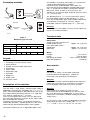
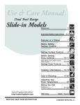
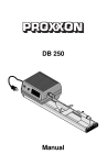
TBM 115
50
40
30
20
10
0
Manual
Spare parts list
Please order spare parts in writing from PROXXON Service Center
(address on back of instruction manual)
Bench drill machine TBM 115
Part No.:
Designation
Part No.:
Designation
28 128-01
Cover
28 128-35
Screw
28 128-02
Drive belt
28 128-36
Ball bearing
28 128-03
Motor belt pulley
28 128-37
Corrugated washer
28 128-04
Set screw
28 128-38
Pulley
28 128-05
Flange sleeve
28 128-39
Circlip
28 128-06
Motor mounting screw
28 128-40
Washer
28 128-07
Washer
28 128-41
Screw
28 128-08
Machine housing
28 128-42
Flange
28 128-09
Switch housing base
28 128-43
Pin
28 128-10
Connecting clamp
28 128-44
Rod
28 128-11
Anti-kink grommet
28 128-45
Sleeve
38 128-12
Connection cable
28 128-46
Feather key
28 128-13
Fastening screw
28 128-47
Scale pointer
28 128-14
Machine switch
28 128-48
Clamp
28 128-15
Connection box
28 128-49
Knurled screw
28 128-16
Strain relief
28 128-50
Nut
28 128-17
Screw
28 128-51
Knurled screw
28 128-18
Rod
28 128-52
Drill table
28 128-19
Circlip
28 128-53
Stop
28 128-20
Nut
28 128-54
Spigot nut
28 128-21
Feed shaft
28 128-55
Drill chuck
28 128-22
Feed lever
28 128-56
Drill spindle
28 128-23
Set screw
28 128-57
Clamping screw
28 128-24
Connection
28 128-58
Circlip
28 128-25
Drill lever
28 128-59
Pulley
28 128-26
Pin
28 128-60
Ball bearing
28 128-27
Spring
28 128-61
Flange
28 128-28
Pin
28 128-62
Fastening screw
28 128-29
Fork
28 128-63
Belt pulley, drill spindle
28 128-30
Ball head
28 128-64
Toggle screw
28 128-31
Steel column
28 128-65
Knurled screw
28 128-32
Set screw
28 128-66
Lower housing cover
38 128-33
Motor
28 128-67
Screw
28 128-34
Retaining screw
28 128-99
Operating Instructions
-2-
Schematics
65
1
2
3
4
5
64
6
63
7
62
57
61
60
59
58
8
9
10
11
12
16
13
17
18
49
14
68
15
13
21
48
20
39
38
37
36
35
47
46
22
19
23
24
25
26
27
45
56
30 27
44
34
43
42
36
33
29
28
31
67
40
55
66
41
32
54
53
52
51
50
-3-
1
3
1
A
2 500 B
10
3
00 10
15
0
00 2000
30
00
10
Wm
50 40 30 20 10 0
kfjk gslgk
eip fgjk s rtk
kfjk
üo wi pie jk ögfkg
oo
igji
sjs
rjg ssüdpii
öo
pp j we f
bjs ogkso iipi r fpieoutg
ö ps g sd g
igjg
do osdggpsg ijgv
igjv j
ss
ps ks p jgs idv
od
igjs j
p gjig
i
ps
50
40
30
20
10
0
2
9
4
8
7
6
65
Fig. 1
40
40
30
30
20
20
10
10
0
0
4
2
A
3
B
2
1
1
Fig. 2
Fig. 3
40
30
20
10
0
1
3
Fig. 4
-4-
2
1
2
Fig. 5
Stufe II
Stage
Stage
Stufe IIII
Stage
Stufe III
III
A
B
C
1.800/min
1800 rpm
4.700/min
4700 rpm
8500 rpm
8.500/min
1
A
1
2
50
40
Fig. 6
Fig. 7
1
2
1
A
2 500 B
1
3 000 10
15
0
00 200
30 0
00
50
W
m
kfj gslg
k
eip fgjk ks rt
k
üo wi p fjkjkkögfk
o ie
g
rjg o ss dpii igjij sjs
öo üo pp we f e
bjs gk iip r fp ou
ö p sog i sd ig tg
sd os gp ijg igjg
os dg sg vig j
s p ks p
jgs jv id
so
igjs vj
dp
i
gji
40
Fig. 8
Fig. 9
2 500 B
1
3 000 10
W
15
0
m
kfj gslg 00 20
k
0
eip fgjk ks
30 0
rt
üo wi p kfjkjkkög
oo ied ig fkg 00
2
50 40 30 20 10 0
rjg ss pii jij s
öo üo p w jsf
bjs gk piip er eo
ö p so i s fpig utg
sd g o dgp ijg ig
os sd sg v jgj
s p gk p igjv
jgs id
so s
igjs vj
dp
gjig
i
ps
3
1
50
40
30
20
10
0
Fig. 10
Fig. 11
-5-
Foreword
Dear customer!
The PROXXON Bench drill press TBM 115 is a precisely
working and powerful machine.
This instruction manual covers:
• safety regulations
• operation and maintenance
• spare parts list
Please read carefully!
Using this instruction manual will
• make it easier for you to get used to the machine,
• help prevent faults occurring due to improper use
and
• increase the service life of your machine.
Keep this instruction manual in an easily accessible
place.
Only operate this machine if you are qualified to do so
and follow the guidelines in this instruction manual.
PROXXON does not accept responsibility for the safe
functioning of the machine
• if it is handled in a manner which constitutes
improper use,
• if it is used for other purposes which are not
specified in the instruction manual,
• if the safety regulations are not observed.
• Warranty claims are invalid if the machine is
incorrectly operated, or the machine has not been
sufficiently maintained.
In the interests of your safety, please always observe
the safety regulations.
Only use genuine PROXXON spare parts.
We reserve the right to make further alterations for the
purpose of technical progress.
We wish you every success with your machine.
General safety instructions
Read and become familiar with this entire instructions
manual. Learn the tool`s applications, limitations and
possible hazards.
1. KEEP GUARDS IN PLACE and in working order.
2. REMOVE ADJUSTING KEYS AND WRENCHES. Form
habit of checking to see that keys and adjusting
wrenches are removed from tool before turning it on.
3. KEEP WORK AREA CLEAN. Cluttered areas and drill
press es invite accidents.
4. DON'T USE IN DANGEROUS ENVIRONMENT. Don't
use power tools in damp or wet locations, or expose
them to rain. Keep work area well lighted.
5. KEEP CHILDREN AWAY. All visitors should be kept in
safe distance from work area.
6. MAKE WORKSHOP KID PROOF with padlocks,
master switches, or by removing starter keys.
-6-
7. DON'T FORCE TOOL. It will do the job better and
safer at the rate for which it was designed.
8. USE RIGHT TOOL. Don't force tool or attachment to
do a job for which it was not designed.
9. USE PROPER EXTENSION CORD. Make sure your
extension cord is in good condition. When using an
extension cord, be sure to use one heavy enough to
carry the current your product will draw. An
undersized cord will cause a drop in line voltage
resulting in loss of power and overheating. Table 1
shows the correct size to use depending on cord
length and nameplate ampere rating. If in doubt, use
the next heavier gage. The smaller the gage number,
the heavier the cord.
Exception No. 1: The reference to the table and the
table itself may be omitted if a statement indicating
the appropriate gage and length is incorporated into
the instruction.
Exception No. 2: The information regarding
extension cords need not be provided for a
permanently connected tool.
10. WEAR PROPER APPAREL. Do not wear loose
clothing, gloves, neckties, rings, bracelets, or other
jewelry which may get caught in moving parts.
Non-slip footwear is recommended.
Wear protective hair covering to contain long hair.
Exception: The reference to gloves may be omitted
from the instructions for a grinder.
11. ALWAYS USE SAFETY GLASSES. Also use face or
dust mask if cutting operation is dusty. Everyday
eyeglasses only have impact resistant lenses, they
are NOT safety glasses.
12. SECURE WORK. Use clamps or a vise to hold work
when practical. It's safer than using your hand and it
frees both hands to operate tool.
13. DON'T OVERREACH. Keep proper footing and
balance at all times.
14. MAINTAIN TOOLS WITH CARE. Keep tools sharp
and clean for best and safest performance. Follow
instructions for lubricating and changing
accessories.
15. DISCONNECT TOOLS before servicing; when
changing accessories, such as blades, bits, cutters,
and the like.
16. REDUCE THE RISK OF UNINTENTIONAL
STARTING. Make sure switch is in „off“-position
before plugging in.
17. USE RECOMMENDED ACCESSORIES. Consult the
owner's manual for recommended accessories. The
use of improper accessories may cause risk of injury
to persons.
18. NEVER STAND ON TOOL. Serious injury could
occur if the tool is tipped or if the cutting tool is
unintentionally contacted.
19. CHECK DAMAGED PARTS. Before further use of the
tool, a guard or other part that is damaged should be
carefully checked to determine that it will operate
properly and perform its intended function check for
alignment of moving parts, binding of moving parts,
breakage of parts, mounting, and any other conditions
that may affect its operation. A guard or other part that
is damaged should be properly repaired or replaced.
20. DIRECTION OF FEED. Feed work into a blade or
cutter against the direction of rotation of the blade
or cutter only.
21. NEVER LEAVE TOOL RUNNING UNATTENDED.
TURN POWER OFF. Don't leave tool until it comes
to a complete stop.
Additional safety regulations
WARNING
IMPORTANT
Additional safety instructions for drill presses:
• Ensure the workplace is tidy.
• Check the unit for damage before use (connection
cable, protective devices, etc.), have defective
parts replaced by qualified personnel.
• This unit corresponds to the pertinent safety
regulations.
• Repairs (e.g., replacement of the power supply
lead) may only be performed by a qualified
electrician.
• Never work without the safety equipment fitted.
• Do not use electrical power tools in the rain, in
damp surroundings or in the vicinity of flammable
liquids or gases.
• Only use the tool when the handle is dry and free
from grease.
• Avoid contact with earthed components, e.g.,
pipes, radiators, ovens and refrigerators.
• Protect the connection lead from heat and sharp
edges and
• route it so it cannot be damaged.
• Do not remove the plug from the socket by pulling
on the cable.
• Do not pick up the unit by the cable.
• Keep children and third parties away from the
workplace.
• Keep tools in childsafe locations when not in use.
• Do not overload the tool.
• Do not use the tool to perform operations for
which it is not suitable.
• Replace blunt tools in good time.
• Visually inspect application tools to ensure they
are in good working order and suitable for the task
prior to setting up the job.
• Fasten tools securely.
• Clean the unit thoroughly following all work.
• Disconnect the plug from the power supply when
the unit is not in use, before performing
maintenance, tool replacement or repair work.
• Only plug the unit in when the unit is switched off.
• Always wear protective goggles (danger of tool
breakage).
• If necessary, wear a protective dust mask.
• Only use appropriate working clothes (no loose
sleeves, ties, jewelry).
• Wear a hair net if you have long hair.
• Only use accessories and spare parts
recommended by PROXXON.
• Observe the max. permitted rotational speed.
• If necessary, use dust extract equipment.
• Do not use the tool when you are tired or under
the influence of alcohol.
• Keep fingers away from rotating or fast moving
tools (saws, etc.).
• Keep the operation instructions in a safe place.
For Your Own Safety Read Instruction Manual Before
Operating Bench Drill Press
a) Wear eye protection.
b) Do not wear gloves, necktie, or loose clothing.
c) Clamp workpiece or brace against column to prevent
rotation.
d) Use recommended speed for drill accessory and
workpiece material.
GROUNDING INSTRUCTIONS:
In the event of a malfunction or breakdown, grounding
provides a path of least resistance for electric current
to reduce the risk of electric shock. This tool is
equipped with an electric cord having an equipmentgrounding conductor and a grounding plug.
The plug must be plugged into a matching outlet that is
properly installed and grounded in accordance with all
local codes and ordinances. Do not modify the plug
provided – if it will not fit the outlet, have the proper
outlet installed by a qualified electrician.
Improper connection of the equipment-grounding
conductor can result in a risk of electric shock. The
conductor with insulation having an outer surface that
is green with or without yellow stripes is the
equipment-grounding conductor. If repair or
replacement of the electric cord or plug is necessary,
do not connect the equipment-grounding conductor to
a live terminal. Check with a qualified electrician or
service personnel if the grounding instructions are not
completely understood, or if in doubt as to whether the
tool is properly grounded.
Use only 3-wire extension cords that have 3prong
grounding plugs and 3pole receptacles that accept the
tool's plug.
Repair or replace damaged or worn cord immediately.
This tool is intended for use on a circuit that has an
outlet that looks like the one illustrated in Sketch A in
Figure 12. The tool has a grounding plug that looks like
the plug illustrated in Sketch A in Figure 12. A
temporary adapter, which looks like the adapter
illustrated in Sketches B and C, may be used to
connect this plug to a 2-pole receptacle as shown in
Sketch B if a properly grounded outlet is not available.
The temporary adapter should be used only until a
properly grounded outlet can be installed by a qualified
electrician. The green-colored rigid ear, lug, and the
like, extending from the adapter must be connected to
a permanent ground such as a properly grounded
outlet box.
-7-
Grounding methods
The spindle is essentially free of play as a result of the
3 high quality ball bearing assemblies.
For the insertion of MICROMOT steel collets it is
recessed, but also threaded for attaching drill chucks
with 3/8" thread (for this option see below the Roehm
drill chuck, which we offer as an accessory). The
spindle has an extremely high rotational accuracy and a
1 3/16" (30 mm) feed.
METAL SCREW
COVER OF GROUNDED
OUTLET BOX
GROUNDING
PIN
The quill diameter is 1 1/4" (32 mm) with return spring,
the throat depth (column to drill spindle) 5 1/2" (140
mm). The unit provides quick coarse height adjustment
of headstock via clamp lever. The max. height
(worktable surface to spindle end) is 5 1/2" (140 mm).
<B>
<A>
ADAPTER
GROUNDING
MEANS
<C>
Warning!
This Drill press is for indoor use only. Do not expose to
rain or use in damp locations.
GROUNDING
PIN
<D>
Fig. 12
Technical data
Table 1
Minimum gage for cord
Ampere Rating
Volts
Total length of cord in feet
120 V 25 ft. 50 ft.
More
Than
Not More
Than
0
6
Dimensions
100 ft.
150 ft.
AWG
18
16
16
14
Legend
1
2
3
4
5
6
7
8
9
10
Fastening screw for machine cover
Drill feed lever
Handle screw for height adjustment
Drill column
Power cable
Adjustable stop
Drill table
Spigot nut
Depth scale
ON-OFF switch
Description of the machine
The unit offers a high quality machined work table of
ribbed die-cast aluminum (worktable size 8 21/32" x 4 23/32"
(220 x 120 mm) providing an adjustable fence with scale.
The solid, hard-chromed steel column is 11" high (280
mm) and has a diameter of 3/4" (20 mm).
The 110-120V/85W motor, which runs very quiet and
has a long life expectancy is built in to the super stable
die-cast head of the machine.
The power transmission by 3-step aluminum pulleys
and flat belt provides 3 spindle speeds of 1,800, 4,700
and 8,500 rpm allowing triple torque at low speeds.
The chrome feed lever has an adjustable depth scale.
-8-
Throat (inner face of column to
middle of drill chuck)
max. space table surface spindle end
Quill feed
approx. 5.5" (140 mm)
approx. 5.5" (140 mm)
approx. 1.2" (30 mm)
Motor
Voltage:
Power:
Idle speed of spindle:
Noise development:
115 V, 60 Hz
hp (85 Watt)
1.800, 4.700, 8.500 rpm
≤70 dB (A)
1/8
Accessories
Warning!
For your own safety, use only drills sized and
recommended for this drill press . Follow the
instructions that accompany the drill press.
Warning!
Use only accessories recommended for this drill press .
Follow the instructions that accompany accessories.
Use of improper accessories may cause hazards.
Warning!
Do not attempt to modify this tool or create
accessories not recommended for use with this tool.
Any such alternation or modification is misuse and
could result in hazardous condition leading to possible
serious injury.
The unit comes with six triple slit MICROMOT precision
steel collets for shaft sizes ranging from 1/32", 1/16", 5/64",
3
/32", 7/64" and 1/8" (1.0, 1.5, 2.0, 2.4, 3.0, 3.2 mm).
Operation
Warning!
To avoid injury from accidental start, make sure the
switch is in the OFF position and the plug is not
connected to the power source receptacle before
changing any parts or drills.
Clamping, changing tools with the optional drill
chuck
(not included)
Attention!
Pull the mains plug out when changing tools.
Warning!
Important!
Safe and precision working practice can only be
ensured with the unit properly secured!
Do not leave the unit switched on if unsupervised.
Before operation:
For your own safety, do not plug the tool into the power
source receptacle or insert the switch key, until the
parts are correctly installed and adjustments have been
made.
• Insert the drill chuck key 2 (Fig. 3) into the drill
chuck (1).
• Turn the drill chuck key in direction "A” to open the
drill chuck.
• Insert the tool into the drill chuck until it bottoms.
First fasten the machine securely on a strong base.
• Turn the drill chuck key in direction "B” to close the
drill chuck and to clamp the tool.
Warning !
To avoid injury from unexpected starting or electrical
shock, do not plug the power cord into a power source
receptacle during unpacking and assembly. This cord
must remain unplugged whenever you are working on
the drill press .
Removing and installing the drill chuck
Note:
This must be done to install the steel collets.
Attention!
Pull the mains plug out beforehand.
Clamping, changing the tool
Warning !
For your safety, never connect the plug to the power
source receptacle until the assembly and adjustment
steps are completed, and you have read and
understood the safety and operating instructions.
1. Insert the pin 3 ( Fig. 4) into the bore and block the
spindle.
2. Insert the drill chuck key (1) and unscrew or tighten
the drill chuck. (2).
Adjusting the spindle speed
Attention!
Tightening the spigot nut without inserting a suitable
shank will damage the collet.
Pull the mains plug out beforehand.
Do not use the machine without protective covering.
Note:
1. Insert the pin 4 (Fig. 2) into the bore and block the
spindle.
2. Unscrew the spigot nut (2).
3. Insert the required collet (3) with the appropriate tool
(1) and retighten the spigot nut.
Note:
Clamp all tools as short as possible. Extremely
protruding shanks will bend and cause eccentric
rotation.
High performance is not achieved by high feeding
speed, but correct and uniform rotary speed.
Belt position "A” = 1.800 rpm
Belt position "B” = 4.700 rpm
Belt position "C” = 8.500 rpm
small drill Ø = high speed
big drill Ø = low speed.
1. Unscrew the knurled screw 1 (Fig. 5) and lift the
cover (2) off.
Attention!
Work careful to avoid damage to the belt.
2. Turn the belt pulley 1 (Fig. 6) in direction "A” and
press the belt slightly down (or up) until it comes
loose.
3. Place the loose belt first on the required pulley (1)
then turn the spindle and force the belt on the
corresponding disc on the motor spindle.
4. Reinstall the cover.
-9-
Adjusting the belt tension
Attention!
Pull the mains plug out beforehand.
Do not use the machine without the protective cover.
1. Unscrew the knurled screw 1 (Fig. 7) and lift the
cover (2) off.
2. Loosen both fastening screws 1 (Fig. 8) and displace
the motor spindle (2) until the required tension is
achieved.
3. Retighten the fastening screws.
4. Reinstall the cover.
Note:
Tighten the belt only so far that the slippage is
eliminated. A too tight belt will deform during a longer
period of rest, which reduces the power of the motor.
Adjusting the distance between tool and work
piece:
Note:
Always adjust the initial position before starting work.
Perform this work after clamping work piece and drill.
1. Support the drill head with your hand against
slipping down.
2. Loosen both handle screws (Fig. 9) and adjust the
height of the drill head until the distance between
drill and work piece is approx. 0.1“ to 0.2“.
3. Retighten the clamping screws.
Do not allow brake fluids, gasoline, or penetrating oils
to come in contact with the plastic parts. They contain
chemicals that can damage or destroy plastics.
Turn switch OFF and always remove plug from power
source before making any adjustments or repairs.
All electrical or mechanical repairs should be done only
by qualified service technicians.
When servicing use only PROXXON replacement parts.
Use of any other parts may create a hazard or cause
product damage.
Any attempt to repair or replace electrical parts on this
drill press may create a hazard unless repair is done by
a qualified service technician. Repair service is
available at your PROXXON service center (You find the
address at address at the back of this manual)
• Lubricate the quill guide (Fig. 11) every 10 operating
hours with a few drops of high quality machine oil.
• After working with the machine remove all chips with
a suitable hand broom or brush.
• Clean the machine regularly with a cloth from all dirt.
• If the machine is not going to be used for a longer
period of time remove the drive belt to avoid
deformation and erratic running.
Recommended Accessories:
Warning!
Use only accessories and spare parts resommended by
PROXXON. See also our catalog or visit our website
www.proxxon.com.
HSS-twist drill set (Art. No.: 28874)
Adjusting the depth stop
Note:
The working stroke of the quill is max. 1,2 ". With the
depth scale it can be limited downwards.
1. Use the drill feed lever to lower the quill until the drill
1 (Fig. 10) touches the work piece.
2. Loosen the clamping screw (2).
3. Adjust the scale pointer (3) to the required drilling
depth (max. 1,2 ") and retighten the clamping screw.
Maintenance
Warning!
Always disconnect the mains plug prior to cleaning and
maintenance operations.
If any part is missing or damaged, do not plug the drill
press in until the missing or damaged part is replaced,
and assembly is complete. To avoid electrical shock,
use only identical replacement parts when servicing
double insulated tools.
To avoid fire or toxic reaction, never use gasoline,
naphtha, acetone, lacquer thinner, or similar highly
volatile solvents to clean the drill press.
- 10 -
Tungsten-vanadium drill bits:
You can get them in different sizes from 0,5 mm
diameter (.02“) up to 2,1 mm (.083“).
Ideal for drilling metal, non-ferrous metals, plastic, pccards and wood. Operating speed: Hard materials
approx. 3000 rpm., soft materials approx. 8000 rpm.
Hard microdrills:
You can get them in different sizes from 1 mm diameter
(.04“) up to 2 mm (.08“). Ideal for drilling glas, semiprecious stones, pocelain, ceramics, marble and other
hard stones.
Tungsten-carbide milling drills:
For drilling, milling and cutting fiber glass or circuit
boards. Also for drilling pearls, etc.
Diamond twist drills:
With natural diamond dust for drilling precious stones
(pearls coral, turquoise)
MICRO compound table KT 70 (NO 27 100):
Made of surface treated solid aluminum and fitted with
adjustable dovetail slides and three T-slots
manufactured to the MICROMOT standard (12 x 6 x
5 mm, approx. 15/32" x 15/64" x 13/64").
The clamps and securing bolts are included.
LIMITED WARRANTY OF PROXXON POWER TOOLS FOR HOME USE
Prox-Tech, Inc., (“Seller”) warrants to the
original purchaser only, that all PROXXON
consumer power tools will be free from
defects in material or workmanship for a
period of two years from the date of
purchase. Seller’s sole obligation and your
exclusive remedy under this limited
warranty and, to the extent permitted by
law, any warranty or condition implied by
law, shall be the repair or replacement of
parts, without charge, which are defective
in material or workmanship and which have
not been misused, carelessly handled, or
misrepaired by persons other than Seller or
Authorized Service Station. In the event of
a failure of a product to conform to this
written warranty, please refer to the Service
and Repair section on the back of this
manual and take action accordingly. This
Limited Warranty does not apply to
accessory items such as circular saw
blades, drill bits, router bits, jigsaw blades,
sanding belts, grinding wheels and other
related items. Damage to the product
resulting from tampering, accident, abuse,
negligence, unauthorized repairs or Some
states in the U.S. and some Canadian
provinces do alterations, unapproved
attachments or other causes unrelated to
problems with material or workmanship are
not covered by this warranty.
Any implied warranties shall be limited in
duration to two years from date of
purchase. Not allow limitations on how
long an implied warranty lasts, so the
above limitation may not apply to you. In
no event shall seller be liable for any
incidental or consequential damages
(including but not limited to liability for loss
of profits) arising from the sale or use of
this product. Some states in the U.S. and
some Canadian provinces do not allow the
exclusion or limitation of incidental or
consequential damages; so the above
limitation or exclusion may not apply to
you. This limited warranty gives you
specific legal rights, and you may also
have other rights, which vary from state to
state in the U.S., province to province in
Canada and from country to country. This
limited warranty applies only to PROXXON
power tools sold within the United States
of America, Canada, the commonwealth of
Puerto Rico and Mexico. For warranty
coverage within other countries contact
your local PROXXON Importer.
- 11 -
SERVICE AND REPAIR
Your device does not work properly? Please read the operating
instructions again carefully. If the unit is in fact defective, please
send it to:
Prox-Tech, Inc.
Attn.: PROXXON Service Center
2555 Tate Blvd. S.E.
Hickory, NC 28601
Spare Parts
You can also order any necessary spare parts from our Service
Center at the above address. Please check the article-number
of the tool concerned on the nameplate of the tool and define
the part needed by using the explosion drawing in the manual
that came with the tool. Every part has a specific number
(5 digit-XX). Please provide us with this number when ordering.
For any further information call us toll free at 1-877-PROXXON
(1-877-776 9966) or visit us on the web at www.proxxon.com/us.
Made in Luxemburg
Distributed in the U. S. by Prox-Tech, Inc.
We reserve the right to make further alterations for the purpose of technical progress.
Art.Nr. 28128-99 PR 703710701J
Please make sure, that your tool is carefully packaged and
include a copy of your dated proof of purchase. You will help
us to react even quicker, if you describe the problem in short
and please don’t forget to include your name, address and
daytime telephone number. We will respond in a prompt and
reliable manner.