1
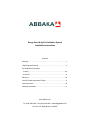
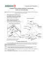
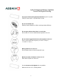
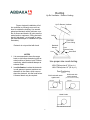
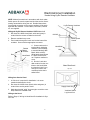
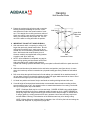
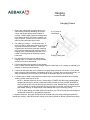
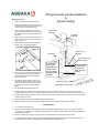
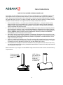
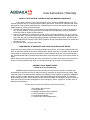
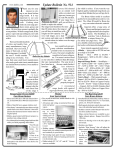
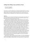
RANGE HOOD INSTALLATION INSTRUCTIONS
ABBAKA Hoods Using Hy-Ex Remote Ventilators
PLEASE READ & SAVE THESE INSTRUCTIONS
ALL HOODS MUST BE INSTALLED BY A QUALIFIED INSTALLER OR SERVICE AGENCY
WARNING - TO REDUCE RISK OF FIRE, ELECTRIC SHOCK OR INJURY TO PERSON, OBSERVE
THE FOLLOWING:
A. Installation work and electrical wiring must be done by qualified person(s) in accordance with all applicable codes and standards, including fire-rated construction. Switch power off at service panel and lock
the service disconnection means to prevent power from being switched on accidentally during installation.
B. When cutting or drilling into wall or ceiling, do not damage electrical wiring and other hidden utilities.
C. All hoods must always exhaust to the outdoors.
D. Sufficient air is needed for proper combustion and exhausting of gases through the flue (chimney) of
fuel burning equipment to prevent back drafting. Local building codes may require the use of make-up
air. Consult your local HVAC professional for specific requirements in your area. Follow the heating
equipment manufacturer’s guideline and safety standards such as those published by the National Fire
Protection Association (NFPA), and the American Society for Heating, Refrigeration and Air Conditioning Engineers (ASHRAE), and state, municipal and local code authorities. The correct voltage, frequency and amperage must be supplied to the appliance from a dedicated, grounded circuit which is
protected by a properly sized circuit breaker or time delay fuse.
E. Warning - To reduce risk of fire, use only metal ductwork.
F. Use this unit in the manner intended by the manufacturer. If you have questions, contact the manufacturer.
INSTALLER: Please retain these instructions for reference, then leave them with the homeowner.
HOMEOWNER: please read and keep the instructions for future reference.
If you have questions concerning the installation of this product, call ABBAKA at (800) 548-3932.
www.abbaka.com
Tel. (800) 548-3932 - Fax (800) 548-3930 - [email protected]
P.O. Box 215, Bodega Bay, CA 94954
Range Hood & Hy-Ex Ventilation System
Installation Instructions
Contents
Warnings ............................................................................................ 1
Unpacking and Planning .................................................................... 3
Pre-Installation Preparation
Ducting ......................................................................................... 4-5
Electrical .......................................................................................... 6
Mounting.......................................................................................... 7-8
Liner Re-Install and System Testing .................................................. 9
Care Instructions .............................................................................. 10
Warranty Information........................................................................ 11
www.abbaka.com
Tel. (800) 548-3932 - Fax (800) 548-3930 - [email protected]
P.O. Box 215, Bodega Bay, CA 94954
Unpacking and Preparation
WARNING: HOOD SURFACE SENSITIVE TO SCRATCHING
DO NOT LIFT HOOD BY RAILS
ABBAKA range hoods consist of the hood shell and a liner, which fits into the base of the hood shell and
houses the lighting, filters and controls.
1. After the hood has been uncrated, set it on
a flat, padded surface, such as a blanket to
protect the hood’s finish. Remove the wrap
from the base of the hood and lay the hood
down on a long side of the base.
2.
Hood Components
Note: If hood is fitted with utensil rail,
cushion rail before laying on side.
Remove Light Panel screws (A). Pop out
Light Panel (B) to access screws that attach
Duct
Light Panel & Liner Removal
Hood Stack
Typical Island
Hood Ceiling
Joist Framing
Hood Shell
C
B
Liner
Light/Switch
Control Panel
A
Light Only Panel
liner to interior of hood shell. Remove
screws (C) and set the liner aside.
PLANNING CONSIDERATIONS
In order for the ABBAKA luxury range hood or any hood to operate properly, it must be sized correctly, have adequate blower capacity, be hung properly (centered over cook top and close enough to
burners), and be vented correctly.
NOTE : The hood should be centered over the cooking surface.
NOTE : The recommended mounted height of the hood bottom above the cooking surface is 30-34”.
For the Cylindra hood, maximum mounted height is 27” above cooking surface.
NOTE : Round stack island hoods will be supplied with a mount bracket. A bracket may be supplied for
support of tall hoods.
NOTE : When Mounting Island Hoods - Do Not Close Ceiling Before Installation Is Complete.
3
Electrical
Knock-Out
Ventilator
Switch Leg
Knock-Out
Hy-Ex Professional Exterior Ventilator
Correct Ducting and Venting
Use proper sized smooth galvanized ductwork- Hy-Ex 1.4 (1400
CFM) 10” round; Hy-Ex 1.0 (1000 CFM) 8” round
Do not use flexible duct.
Ribbing creates resistance to airflow, reducing exhaust efficiency.
Do not space elbows closer than 4’ to each other.
Do not make "S" turns or double elbows anywhere in duct run.
Do not reduce suggested minimum size anywhere in duct run.
Even in wall louvers and roof jacks. (10” round = 78 Sq. In.;
8” round = 51 Sq. In.)
Make gradual turns in duct run.
Do turn sharp corners. Air cannot make 90° turns.
Maximum number of elbows in a duct run is 3.
Each elbow is equal to 6’ of duct run.
Use the shortest and straightest duct run possible.
Maximum duct run is 51’, including elbows.
4
Ducting
Hy-Ex Ventilator - Exterior Venting
Hy-Ex Remote Ventilator
Proper ductwork installation will allow ventilator to efficiently move air from
hood to outside the building. Use smooth
galvanized ductwork with a minimum number of elbows and bends. All joints must be
sealed and run upstream. Ceiling ductwork
should “stub down”, cut to length, to mate
with backdraft damper of installed liner (see
illustration).
Ceiling
Duct ‘Stub’
From Ceiling
Ductwork is not provided with hood.
Backdraft
Damper
Liner
Exhaust Outlet
Liner
Hood Shell
NOTES
1. It is recommended to have the range
hood on site before determining the terminal position of the duct ‘stub’. Before
measuring, attach backdraft damper to
exhaust outlet.
Use proper size round ducting.
2. In cold climates, insulate the ductwork
in cold spaces to prevent moisture condensation in the winter, which can run
down the ductwork, into the hood below.
A thermal break may be required.
Duct Positioning
1000 CFM requires 8” (50 sq. in.)
1400 CFM requires 10” (78 sq. in.)
Top View
Wall hoods with stack
against wall
Wall Side
Wall hoods with
stack centered
(Luna and Quantum models)
Wall Side
1”
Duct Location
Duct Location
Island Hoods
Duct Location
Duct centered front to rear
5
Electrical/Liner Installation
Hoods Using Hy-Ex Remote Ventilator
NOTE: Make all connections in accordance with local codes.
Switch power off at service panel and lock the service disconnecting means before wiring the unit. Detailed instructions
for electrical connection to the remote ventilator will be packaged with the ventilator. Power cables, connectors, conduit
etc. not supplied.
Hy-Ex Remote Ventilator
Wiring the Hy-Ex Remote Ventilator HYEX-1.4 or 1.O:
1. Run three #14 AWG wires (black, white and green) in
conduit from the remote ventilator to the hood.
120VAC
2. Remove ventilator’s top cover.
Motor Speed
Control
3. Feed conduit through the knock out into the base of the
ventilator. Secure with an appropriate connector.
Flexible
Metal
Conduit
Duct
Hood Stack
4. Connect wires to the
terminal block inside the
ventilator; connect Black
to terminal labeled LINE/
Black, White to NEU/
White terminal and Green
to GND/ Ground terminal. Replace ventilator’s
cover.
5. Run the 3-wire bundled conduit from the ventilator to the hood. Make
the electrical “whip” long
enough to reach to the
countertop below the installed hood.
Hood Shell
Liner
Liner Knock-out
Top View
Wiring from Service Panel
1. A 15A circuit is required for installation. It is recommended to dedicate the circuit.
2. Run three #14 AWG wires: (black, white and green) in
conduit from service panel to hood.
3. Make the electrical “whip” long enough to reach the countertop below the installed hood.
Wiring at the Hood:
Refer to Page 9, “Wiring At Hood/Liner Re-Installation & System Test.
6
Supply Knock-Out
Ventilator Switch
Leg Knock-Out
Hanging
Wall Mounted Hoods
Ceiling
1. Protect the cooktop with a furniture pad or consider
building a worktop straddling the counter. Center
and square the hood to the actual location of cooktop. Lift in straight line to ceiling and trace outline of
stack onto ceiling. Lower hood to rest position. Alternately, use a plumb line and "project" the four corners of the stack to ceiling and mark the position.
Wall Stud
Upper Wall
Attachment
Point
2. IMPORTANT: DO NOT LIFT HOOD BY RAILS.
3. With a sheetrock knife, cut opening in ceiling 1/16”
larger than previously traced stack outline. Should
ceiling not be perfectly level, stack top can be recessed into cut out eliminating possible shadow line.
Note: Wall hoods with centered stack (Luna &
Quantum models) are supplied with ceiling bracket
to position and “plum” stack top.
Hood Base
Wall
Attachment Points
4. NOTE: After installation is completed, any gap between ceiling opening and hood stack can be filled
with paint-ready acrylic caulking and painted or
framed with molding. Optional decorative ceiling cover plate is offered for difficult to patch wood ceiling.
5. Wall mounted hoods may be attached to the wall at the stud position (see figure above). In some
cases, the hood may need to be attached to a plywood backing previously installed in wall behind
hood.
6. Drill mount holes through solid back wall of hood cabinet (use cobalt drill bit on stainless hoods) 2"
up from base of hood on center with at least two studs. Drill upper attachment hole as close to hood
centerline and as high up from hood bottom as possible.
7. Lift hood into position and secure firmly to wall studs or backing with lag bolts and lock nuts.
8. If overall height of hood positions bottom below recommended clearance above cooking surface,
excess stack may be cut off. Any ragged cut line or material discoloration from cutting, can be hidden by recessing stack top into sheetrock.
NOTE 1: Stainless Steel may be cut in several ways - POWER JIG SAW using carbide blades
designed specifically for ferrous or hardened metals (24 teeth per inch), ANGLE GRINDER or
heavy duty angle drill using an abrasive type aluminum oxide, diamond edge, or carbide wheel.
If using a jigsaw, the cutting process will be slow, generate a lot of heat, and may require several saw blades. "Blueing" or discoloration of the stainless steel may occur during cutting.
NOTE 2: When drilling use cobalt drill bits for stainless. Use 1/8" bit for pilot hole and enlarge as
needed with "Step-Drill" or progressively larger bits.
7
Hanging
Island Hoods
Hanging Frame
1. Protect the cooktop with a furniture pad or consider building a worktop straddling the counter.
Center and square hood to actual location of
cooktop. Leading edge of hood should align with
front cooking element, NOT front of cooktop. Using a plumb line, "project" the four corners of the
stack to ceiling and mark stack outline.
2. Cut opening in ceiling 2’ - 3’ wider than stack. If
there is an attic or crawl space above hood, hanging frame can be built from above. If there is a
carpeted room above hood, peel back carpeting
and cut access panel through sub-floor to build
hanging frame. Build hanging frame with 2 x 4’s .
Header off ceiling joists as necessary to frame
hood stack.
2 x 4 Frame for
Hood Stack
Double
Header
Existing Ceiling Joist
3. Pre-drill stack top with holes for attachment to
hanging frame. 6” of stack top should penetrate
ceiling line for secure anchorage.
4. Lift hood and slide exhaust stack up into hanging
frame. Position hood at desired mount height. Span the island with 2 x 4’s resting on scaffolding, for
example, to prop up hood in position.
5. Level hood and temporarily tack in position to hanging frame with sheet rock screws. Firmly attach
stack to hanging frame with bolts, lock washers and nuts. If running duct work through joist bay, cut
away the side above the ceiling line that will allow an adjustable elbow to turn into the bay.
6. If overall height of hood would position the bottom below recommended clearance above cooking
surface, excess stack may be cut off.
NOTE 1: Stainless Steel may be cut in several ways - POWER JIG SAW using carbide blades
designed specifically for ferrous or hardened metals (24 teeth per inch) ANGLE GRINDER or
heavy duty angle drill using an abrasive type aluminum oxide, diamond edge, or carbide wheel.
If using a jigsaw, he cutting process will be slow, generate a lot of heat, and may require several
saw blades. "Blueing" or discoloration of the stainless steel may occur during cutting.
NOTE 2: When drilling use cobalt drill bits for stainless. Use 1/8" bit for pilot hole and enlarge as
needed with "Step-Drill" or progressively larger bits.
7. Replace sheetrock. Any gaps around stack can be filled with paint-ready caulking and painted or
framed with molding. Optional decorative ceiling cover plate is offered for difficult to patch wood ceiling.
8
Wiring At the Hood:
1.
Position hood liner on counter below hood.
2.
Remove Light /Switch Control Panel and Light
Only Panel (or Screw Covering Panel in wall
mount hood) from liner (see Figure A).
3.
Feed conduit from ventilator into knock out
labeled “Ventilator Switch Leg” and secure with
appropriate connector. (Remote or Attic ventilator only).
4.
Feed conduit from service panel into knock out
labeled “Power Supply” and secure with appropriate connector.
5.
Remove filters from liner to simplify mating of
transition top to suspended ductwork.
Wiring At Hood/Liner Re-Installation
&
System Testing
Typical Island
Installation
To Ceiling
Ductwork
Figure A
“Switch Leg” to
Ventilator
Hood Shell
A
Power Supply from
Service Panel
B
C
6.
Lift liner into hood, reaching up through exhaust
outlet to transition top, guide liner into place.
Re-secure liner with # 8 x ½" Phillips head
sheet metal screws.
7.
Lift Light Only Panel up to liner and connect
black wire to black and white to white. Secure
Light Panel to liner wall with screws supplied.
(In wall mount hood secure Screw Covering
Panel.)
2. Lift bottom
edge of liner
flush with hood
bottom. Guide
duct into place
and tape inside.
vertically
1. Cut section
to mate with
duct stub from
ceiling
Light Only Panel
Light /Switch Control Panel
8.
Lift Light/Switch Control Panel up to liner.
9.
Complete “Switch Leg” Connections to Ventilator: black wire from ventilator to the red wire (“Switch Leg”) from motor
speed control, white to white, green to green. (Remote or Attic vent only). Do Not connect to service panel power supply.
10. Complete Power Supply Connections. Connect black wire from service panel to black in Light/Control Switch Panel, white
to white and green to green.
11. Secure Light/Switch Control Panel to liner wall with screws provided.
12. Tape joint between transition top to round ductwork from inside, running strips of metal foil tape vertically.
SYSTEM TESTING
1.
Turn on electrical circuit to hood.
2.
Switch on ventilator. Rotate variable speed control knob clockwise through full range to see if motor speed is changing
accordingly. If motor speed is not changing as knob is rotated, check wiring. NOTE: Motor clicks on at highest speed and
runs progressively slower.
3.
Switch on halogen lights. If they do not light, check to see that bulbs are securely seated in their sockets.
4.
On untreated copper or brass hoods, fingerprints and resulting tarnish or oxidation should be removed with a quality, nonabrasive polish and soft cloth - PLEASE FOLLOW INSTRUCTIONS ON NEXT PAGE.
9
Care Instructions
CARE OF YOUR COPPER OR BRASS RANGE HOOD
Pure copper or brass, polished to a mirror finish, is used in the fabrication of your ABBAKA Range hood of
semiprecious metal. The optional utensil rail and “S” hooks are like wise made of pure mirror- polished
brass. These exotic metals are left in their natural state, uncoated, to provide a finished product of the highest luster and natural, rich color. The nature of copper and brass is to tarnish. However, the beauty of these
materials is that the brilliance of the original finish can be easily retained with a little care.
1. Do not use harsh alkali (i.e., oven cleaners) or acid base detergents (i.e., acid grout cleaner for tile),
abrasive polishes or scouring powders (this is a good rule of thumb for all range hoods regardless of
material or finish. Stainless steel or chrome plating can be scratched. The hard surface to enamel finishes will be dulled and become porous).
2. Tarnish can be removed with a number of readily available brass/copper cleaners and polishes. Follow
the manufacturer’s directions, using a soft cloth (baby diapers are excellent for this purpose). Polish or
wipe in a straight or horizontal direction. DO NOT USE A CIRCULAR MOTION. Use a NON-ABRASIVE
POLISH. ABBAKA makes no specific product endorsements. However, products such as WENOL,
SIMICHROME, and FLITZ have been found effective.
3. Normal body oils are in part alkali in composition. Consequently, fingerprints will turn to tarnish on copper or brass. After polishing, a light application of wax will retard tarnishing. The wax creates a protective
barrier between the metal and tarnish producing moisture or fingerprints. A car wax with silicon, for example, is well suited for the task.
4. Over time, scratching will gradually occur. These fine scratches will eventually work into a smooth, even
patina, much in the manner of sterling silver flatware, or an aged brass hand rail or banister. The patina
is viewed by many as a desirable trait, and in fact, can add character to the hood.
5. Fine scratches can normally be smoothed or blended into an even patina over the course of time. They
can also be completely buffed out by a professional metal refinisher. However, this may require removal
and reinstallation of the hood
Basic maintenance of your copper or brass ABBAKA range hood will ensure that it retains its natural beauty
for generations.
Polish with straight
level motion, parallel
to the bottom of the
hood
NOTE: Different
grain direction on
Barrel Forms or
hoods with
rounded canopy
or exhaust flue
10
Care Instructions / Warranty
CARE OF YOUR ANTIQUE COPPER OR ANTIQUE BRONZE RANGE HOOD
Pure copper or brass is used in the fabrication of your "Antiqued" ABBAKA Range hood. The
optional utensil rail and "S" hooks are likewise made of pure brass. These exotic metals are then chemically aged to create a classic distressed look. A matte lacquer top coat is then applied to the antiqued
metal's surface to "freeze the aging process".
1. DO NOT USE harsh alkali (i.e., oven cleaners) or acid base detergents (i.e., acid grout cleaner for
tile), abrasive polishes, scouring powders or cleaning products containing ammonia, degreasers,
strong chemicals or window cleaner products.
2. Use a non-fragranced, mild soap with a neutral pH, like Ivory Liquid detergent, in a 10 to 1 dilution
with warm water. Use only soft cotton cloth (old baby diapers softened by many washings are excellent). Soak the cloth in the diluted detergent and wipe in a straight blotting motion. DO NOT USE A
CIRCULAR MOTION. DO NOT USE PAPER TOWELS as this wood-based product can scratch and
damage the finish.
3. Dry the hood, again, using soft cotton cloth
MAINTENANCE OF ENAMELED AND STAINLESS STEEL RANGE HOODS
Hoods may be cleaned with any commercially available liquid cleaner. Avoid using cleansers with abrasives, as they may scratch the enamel or stainless steel. Brass utensil rails, if included, may be cleaned
with a copper or brass polish (see previous page). Polished stainless steel rails may be cleaned with a
soft cloth dampened with a mild soap and water solution, then buffed with a dry clean cloth to restore its
luster.
NOTE: Always clean and polish with the "grain" of the hood. The "grain" is the series of fine lines in the
surface of natural polished metal hoods. It is usually horizontal. Do not clean in a circular motion.
ABBAKA LUXURY RANGE HOODS
Limited Three (3) Year Warranty
ABBAKA warrants the products of its manufacturer to be free from defects in materials and
workmanship for a period of three (3) years from date of acquisition by original consumer-owner. Material which proves to be defective after inspection by ABBAKA, will be repaired or replaced at ABBAKA's
option. No claims of labor, shipping costs or consequential damages will be accepted. This warranty
shall not apply to product which has been altered, used for purposes and conditions other than those for
which the product is intended; damaged as a result of shipping, misuse, negligence, accident, faulty installation or maintenance.
The warranty covers the hood cabinet, hood liner and motors.
The warranty does not cover:
A. Freight damage
B. Damage caused by faulty installation
C. Service charges in your home
D. Consequential damage
E. Commercial or other misapplication
11